body JAGUAR X308 1998 2.G Workshop Manual
[x] Cancel search | Manufacturer: JAGUAR, Model Year: 1998, Model line: X308, Model: JAGUAR X308 1998 2.GPages: 2490, PDF Size: 69.81 MB
Page 2417 of 2490
Panels centered between two adjacent panels must have equal gaps on either side. For exceptions to this, refer to the
appropriate specification. Gaps between ad jacent panels or components must not expose harnesses, labels, brackets or
visually poor joint or assembly conditions.
• NOTE: Sliding roof panel clearances are specified without the edge seal installed.
Areas of particular concern are, fuel filler flap, trunk lid to fenders and saddle panels, hood to fenders, grill and headlamps,
sliding roof to main roof panel, door gaps at fenders, B\C posts, roof drip rail an d rocker panel, and bumper cover to fenders
and cross car assemblies
Alignment
Panels must be correctly profiled to maintain cosmetic appearance, and ensure co rrect seating of seals with minimal wind
noise. Areas of particular concern are hood to fenders, trunk lid to fenders and saddle panels, doors to apertures, doors to
fenders and adjacent doors and relationship of the sliding roof panel leading and trailing edges to the main roof panel.
Exterior Fitments
Bezels, trims and lamps must be concentric with apertu res and have equal clearances with adjacent panels.
Areas of particular concern are headlamp to hood, fender and trim panel, exhaust tailpipe trim to bumper cover cut-out,
rear lamp assembly to trunk lid, fender and bumper cover trim, and side feature lines including body side mouldings, fender
to door and door to door.
Exterior Clearances and Alignments-Front
Page 2421 of 2490
Uni-Body, Subframe and Mounting System - Front Axle Crossmember
Removal and Installation
Removal
CAUTION: Replacement of nuts and bolts: Various thread-locking devices are used on nuts and bolts throughout the
vehicle. These devices restrict the number of times a nut or bolt can be used. See section 100-00 for information.
Special Tool(s)
Tie-Rod-End Taper Separator
211-098 (JD 100)
Engine Support Beam
303-021 (MS 53D)
1. Position vehicle on a four-post lift.
2. Raise front of vehicle and support on stands.
3. Remove battery cover and disc onnect ground cable from
battery terminal. Refer to section 86.15.15.
4. Open hood to service position, and fit covers to fenders.
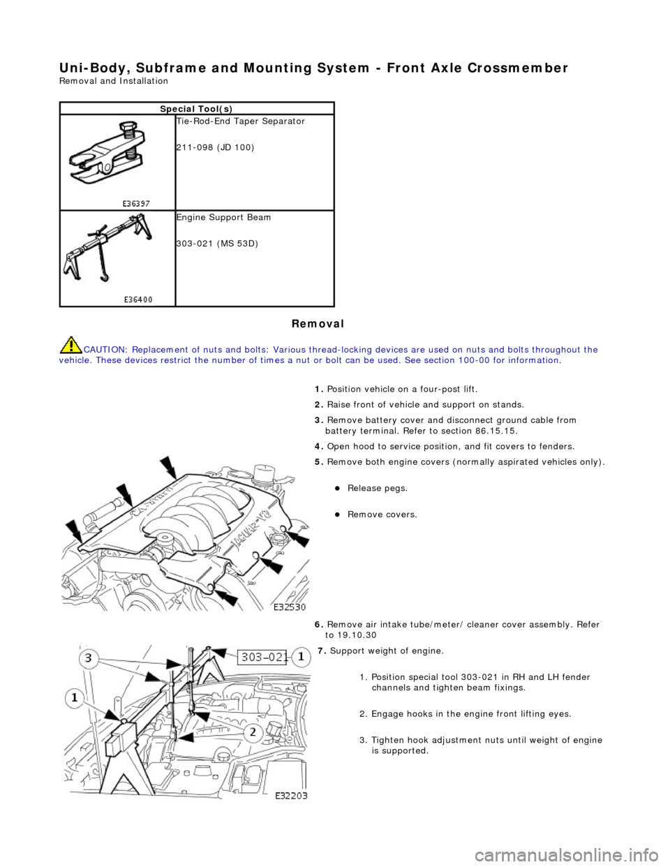
5. Remove both engine covers (nor mally aspirated vehicles only).
Release pegs.
Remove covers.
6. Remove air intake tube/meter/ cleaner cover assembly. Refer
to 19.10.30
7. Support weight of engine.
1. Position special tool 303-021 in RH and LH fender channels and tighte n beam fixings.
2. Engage hooks in the en gine front lifting eyes.
3. Tighten hook adjustment nuts until weight of engine is supported.
Page 2422 of 2490

8. Remove generator front cooling duct.
Remove bolt.
Move duct rearwards to rele ase tang from undertray.
Release front duct from rear vertical duct.
9. Remove scrivets or screws se curing undertray to bumper
cover. Discard scrivets.
10. Remove and discard tiestrap securing undertray to body
brace.
11. At each side of vehicle, remo ve and discard scrivet securing undertray to wheelarch liner.
12. Remove undertray from vehicle.
13. Remove both front road wheels. Refer to Section 100-02.
14. Remove both front road springs. Refer to 60. 20.02.
15. Disconnect wheel speed sensor harness connectors.
Page 2423 of 2490
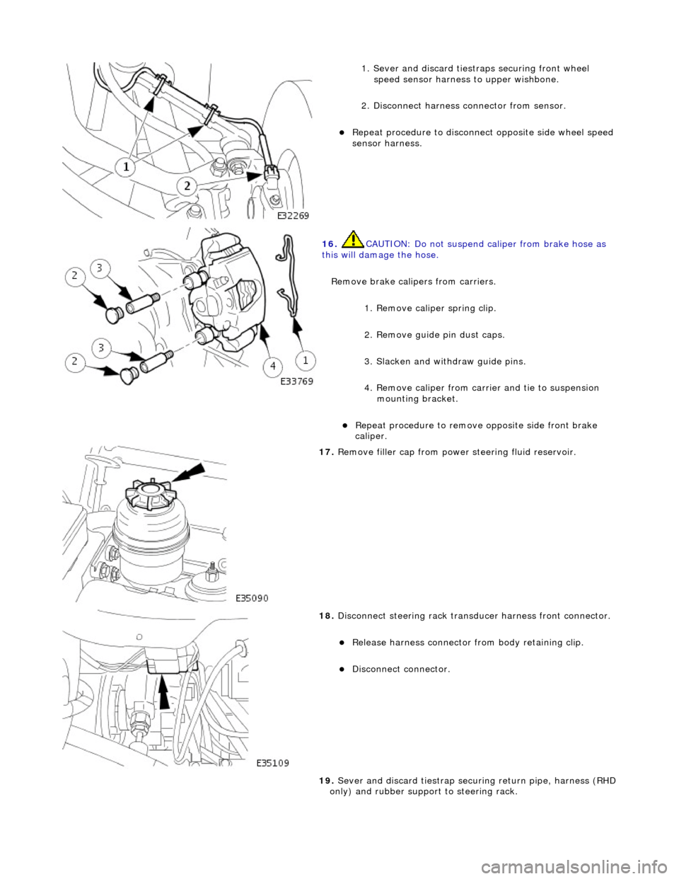
1. Sever and discard tiestraps securing front wheel
speed sensor harness to upper wishbone.
2. Disconnect harness connector from sensor.
Repeat procedure to disconnect opposite side wheel speed
sensor harness.
16. CAUTION: Do not suspend caliper from brake hose as
this will damage the hose.
Remove brake calipers from carriers.
1. Remove caliper spring clip.
2. Remove guide pin dust caps.
3. Slacken and withdraw guide pins.
4. Remove caliper from carrier and tie to suspension mounting bracket.
Repeat procedure to remove opposite side front brake
caliper.
17. Remove filler cap from power steering fluid reservoir.
18. Disconnect steering rack transducer harness front connector.
Release harness connector from body retaining clip.
Disconnect connector.
19. Sever and discard tiestrap secu ring return pipe, harness (RHD
only) and rubber support to steering rack.
Page 2427 of 2490

36. Ensure that steering transducer harness is clear of return pipe and LH side body.
37. Lower and traverse front suspension assembly clear of
vehicle.
38. With assistance, lift front suspension as sembly onto bench.
39. Remove nut securing each tie ro d outer ball joint to steering
arm.
40. Release tie rod ball joint from steering arm.
1. Install special tool 211-098 on tie rod outer ball joint.
2. Tighten tool bolt to re lease ball joint taper pin.
3. Remove tool and release tie rod from steering arm.
Repeat procedure to release opposite side tie rod ball
joint.
41. Remove steering harness fr om LH suspension turret.
Release harness securing clip s from suspension turret.
Mark position of clips on harness.
Remove tape securing clips to harness and discard clips.
42. Disconnect and remove steering harness.
Page 2432 of 2490

10. With assistance position crossbeam/suspension assembly on
jack with protective wood under.
11. Traverse assembly into position below vehicle.
12. Ensure steering harn ess connector is positioned to avoid
damage during crossbeam lift .
13. NOTE: It may be necessary to use a hammer and drift to
finally align new mounting with body location.
Carefully raise crossbeam assembly into position.
Ensure that dowels of both crossbeam mountings are
correctly seated in body locations.
14. Ensure that both engine hydram ounts are correctly seated in
crossbeam locations.
15. Install crossbeam rear mountings.
Align rear mounting rubber with body location.
Install rear mounting securing bolt and nut and tighten
nut to 131-185 Nm.
Repeat procedure to install opposite side rear mounting
bolt and nut.
16. From engine compartment, install but do not tighten
crossbeam front RH bolts.
Page 2436 of 2490
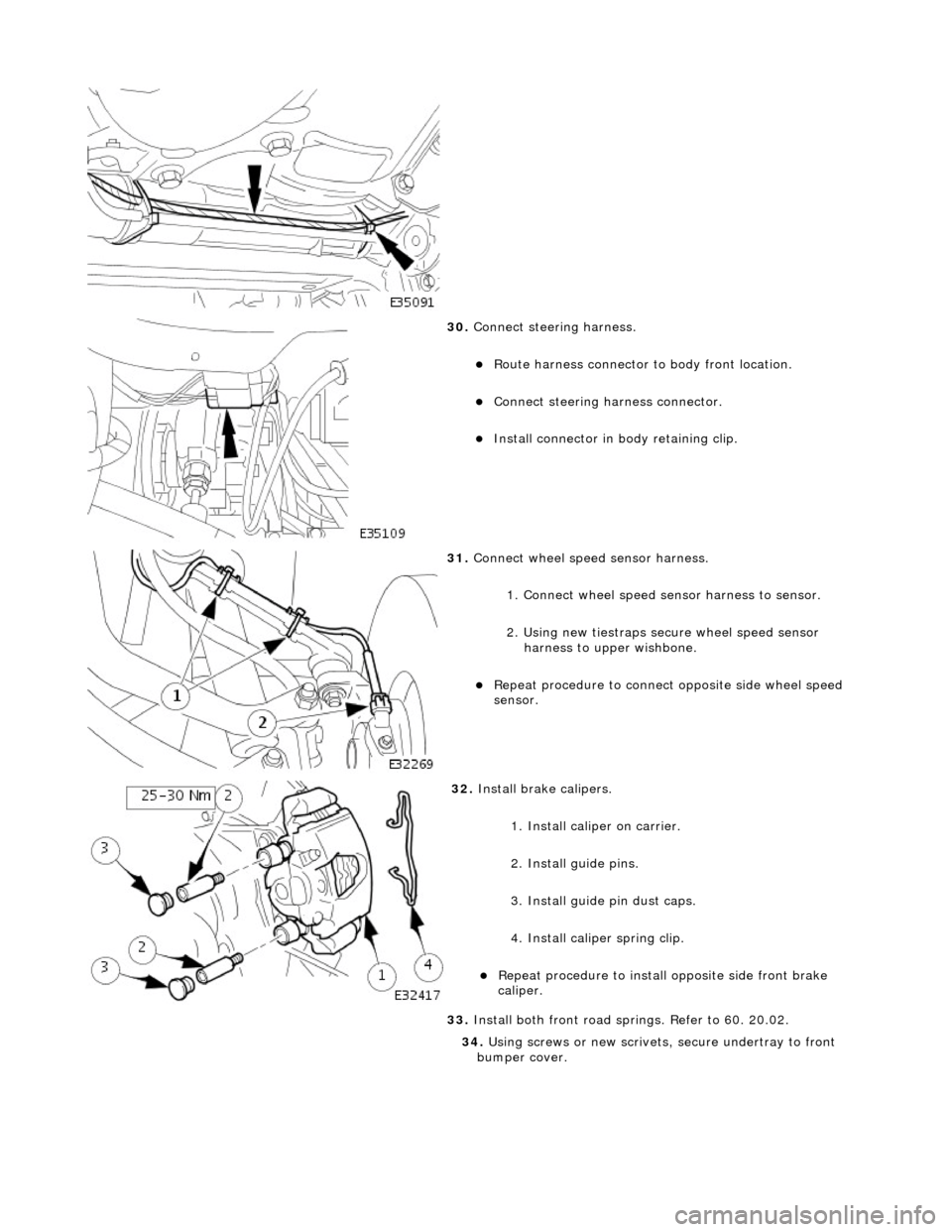
30. Connect steering harness.
Route harness connector to body front location.
Connect steering ha rness connector.
Install connector in body retaining clip.
31. Connect wheel speed sensor harness.
1. Connect wheel speed sensor harness to sensor.
2. Using new tiestraps secure wheel speed sensor harness to upper wishbone.
Repeat procedure to connect opposite side wheel speed
sensor.
32. Install brake calipers.
1. Install caliper on carrier.
2. Install guide pins.
3. Install guide pin dust caps.
4. Install caliper spring clip.
Repeat procedure to install opposite side front brake
caliper.
33. Install both front road sp rings. Refer to 60. 20.02.
34. Using screws or new scrivets , secure undertray to front
bumper cover.
Page 2439 of 2490
Uni-Body, Subframe and Mounting System - Front Axle Crossmember
Front Bushing
Removal and Installation
Removal
CAUTION: Replacement of nuts and bolts: Various thread-locking devices are used on nuts and bolts throughout the
vehicle. These devices restrict the number of times a nut or bolt can be used. See Section 100-00 for information.
Special Tool(s)
Engine Support Beam
303-021 (MS 53D)
Front Camber Tie-down Link
204-114 (JD 133)
1. Position vehicle on a four-post lift.
2. Remove ignition key and en gage steering column lock.
3. Open hood to service position, and fit covers to fenders.
4. Remove battery cover and disc onnect ground cable from
battery terminal. Refer to 86.15.19.
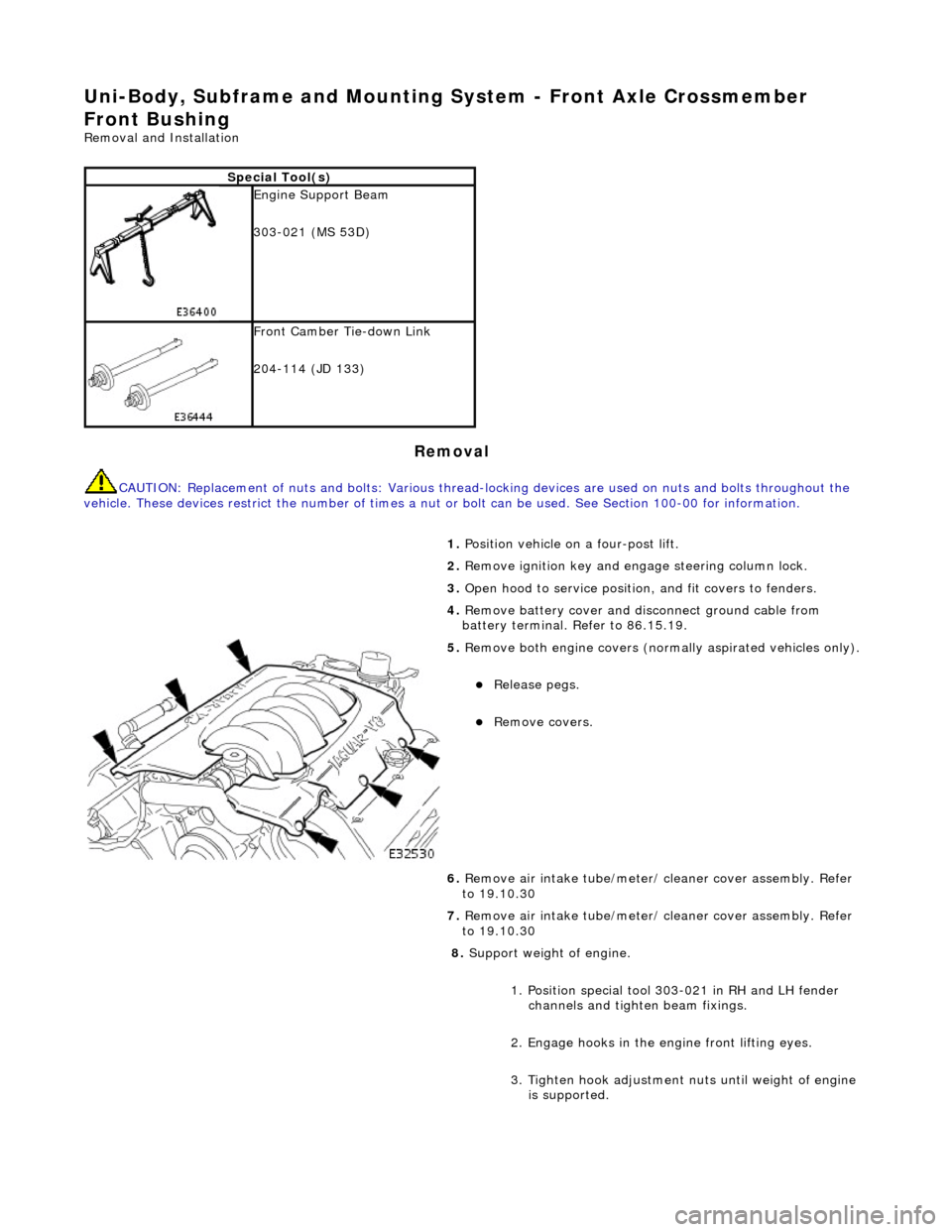
5. Remove both engine covers (nor mally aspirated vehicles only).
Release pegs.
Remove covers.
6. Remove air intake tube/meter/ cleaner cover assembly. Refer
to 19.10.30
7. Remove air intake tube/meter/ cleaner cover assembly. Refer
to 19.10.30
8. Support weight of engine.
1. Position special tool 303-021 in RH and LH fender channels and tighte n beam fixings.
2. Engage hooks in the en gine front lifting eyes.
3. Tighten hook adjustment nuts until weight of engine is supported.
Page 2440 of 2490

9. Raise front of vehicle.
10. Remove generator cool ing duct deflector.
Remove bolt.
Move deflector rearwards to release tangs from undertray.
Release deflector from rear vertical duct.
11. Remove screws or scrivets securing undertray to bumper
cover. Discard scrivets.
12. Remove and discard tiestrap securing undertray to body
brace.
13. At each side of vehicle, remo ve and discard scrivet securing
undertray to wheelarch liner.
Page 2442 of 2490
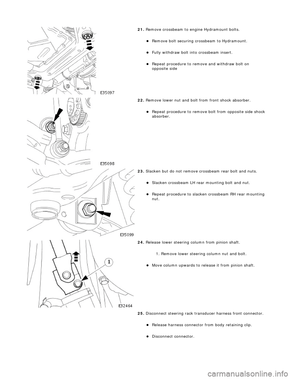
21. Remove crossbeam to engi ne Hydramount bolts.
Remove bolt securing crossbeam to Hydramount.
Fully withdraw bolt into crossbeam insert.
Repeat procedure to remove and withdraw bolt on
opposite side
22. Remove lower nut and bolt from front shock absorber.
Repeat procedure to remove bo lt from opposite side shock
absorber.
23. Slacken but do not remove crossbeam rear bolt and nuts.
Slacken crossbeam LH rear mounting bolt and nut.
Repeat procedure to slacken crossbeam RH rear mounting
nut.
24. Release lower steering column from pinion shaft.
1. Remove lower steering column nut and bolt.
Move column upwards to release it from pinion shaft.
25. Disconnect steering rack transducer harness front connector.
Release harness connector from body retaining clip.
Disconnect connector.