501 JAGUAR X308 1998 2.G Owner's Guide
[x] Cancel search | Manufacturer: JAGUAR, Model Year: 1998, Model line: X308, Model: JAGUAR X308 1998 2.GPages: 2490, PDF Size: 69.81 MB
Page 1874 of 2490

Parking Aid - Rear Parking Aid Speaker
Removal and Installation
Removal
Installation
1.
Remove the parcel shelf.
For additional information, refer to: Parcel Shelf
(501-05
Interior Trim and Ornamentatio n, Removal and Installation).
2. Reposition the sound insulation.
3. Disconnect the electrical connector.
4. Remove the rear parking aid speaker.
1. To install, reverse the removal procedure.
Page 2027 of 2490
Front End Body Panels - Front End Body Panels
Description and Operation
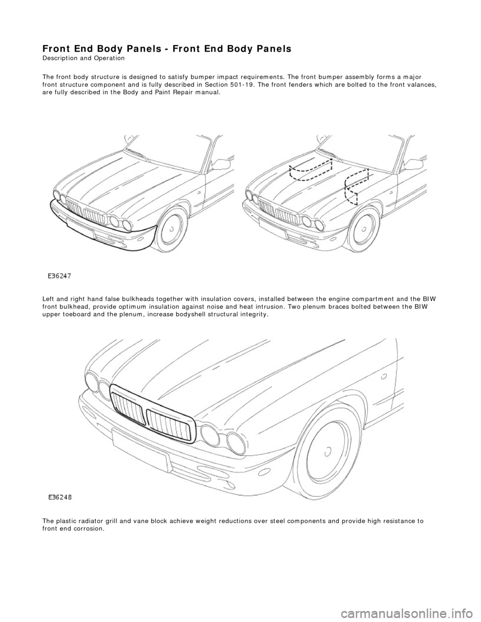
The front body structure is de signed to satisfy bumper impact requiremen ts. The front bumper assembly forms a major
front structure component and is fully desc ribed in Section 501-19. The front fenders which are bolted to the front valances,
are fully described in the Body and Paint Repair manual.
Left and right hand false bulkheads together with insulation covers, installed between the engine compartment and the BIW
front bulkhead, provide optimum insulation against noise and heat intrusion. Two plenum braces bolted between the BIW
upper toeboard and the plenum, increa se bodyshell structural integrity.
The plastic radiator grill and vane block achieve weight reductions over steel components and provide high resistance to
front end corrosion.
Page 2055 of 2490

Interior Trim and Ornamentation - A-Pillar Trim Panel
Removal and Installation
Removal
Installation
1.
Remove the passenger assist handle.
For additional information, refer to: Passenger Assist Handle
(501-05 Interior Trim and Ornamentation, Removal and
Installation).
2. Detach the door aperture weatherstrip.
3. Remove the A-pillar trim panel.
Remove and discard the A-pi llar trim panel fir tree
fasteners.
1. To install, reverse the removal procedure.
Install new fir tree fasteners to the A-pillar trim panel.
Page 2059 of 2490

Interior Trim and Ornamentation - C-Pillar Trim Panel
Removal and Installation
Removal
1. Remove the passenger assist handle.
For additional information, refer to: Passenger Assist Handle
(501-05 Interior Trim and Ornamentation, Removal and
Installation).
2. Detach the rear courtesy/reading light.
3. Remove the rear courtesy/reading light.
Disconnect the electrical connector.
4. Detach the door aperture weatherstrip.
5. Detach the C-pillar trim panel fi r tree fasteners from the BIW.
6. Remove the C-pillar trim pa nel and discard the fir tree
fasteners.
Page 2062 of 2490

Interior Trim and Ornamentation - Engine Cover
Removal and Installation
Removal
Installation
1.
Remove the passenger side and dr iver side bulkhead covers.
For additional informat ion, refer to Section 501
-02 Front End Body Panels.
2. Remove the engine cover.
1. To install, reverse the removal procedure.
Page 2076 of 2490

Interior Trim and Ornamentation - Headliner
Removal and Installation
Removal
Vehicles with roof opening panel
All vehicles
1. Remove the roof opening panel trim.
For additional information, refer to: Roof Opening Panel Trim
(501-17 Roof Opening Panel, Removal and Installation).
2. Remove both C-pill ar trim panels.
For additional information, refer to: C
-Pillar Trim Panel (501-05
Interior Trim and Ornamentatio n, Removal and Installation).
3. Remove both A-pill ar trim panels.
For additional information, refer to: A
-Pillar Trim Panel (501-05
Interior Trim and Ornamentatio n, Removal and Installation).
4. Remove the overhead console.
For additional information, refer to: Overhead Console
(501-12
Instrument Panel and Console, Removal and Installation).
5. Remove the rear window glass.
For additional information, refer to: Rear Window Glass
(501-
11 Glass, Frames and Mechanis ms, Removal and Installation).
6. Disconnect the anti-theft se nsors electrical connector.
7. CAUTION: With the aid of an other technician, support the
headliner to ensure it is not folded or creased during removal.
Remove both sun visors.
For additional information, refer to: Sun Visor
(501-05 Interior
Trim and Ornamentation, Re moval and Installation).
8. NOTE: Left-hand shown, right-hand similar.
Detach the retaining screw cove r from the headliner retaining
trim.
9. NOTE: Left-hand shown, right-hand similar.
Remove the headline r retaining trim.
Page 2079 of 2490

Vehicles with roof opening panel
7. Install both sun visors.
For additional information, refer to: Sun Visor (501-05 Interior
Trim and Ornamentation, Re moval and Installation).
8. Install the rear window glass.
For additional information, refer to: Rear Window Glass
(501-
11 Glass, Frames and Mechanis ms, Removal and Installation).
9. Fit the electrical connectors into the retaining clips at the
overhead console location.
10. Install the overhead console.
For additional information, refer to: Overhead Console
(501-12
Instrument Panel and Console, Removal and Installation).
11. Install both C-pillar trim panels.
For additional information, refer to: C
-Pillar Trim Panel (501-05
Interior Trim and Ornamentatio n, Removal and Installation).
12. Install both A-pillar trim panels.
For additional information, refer to: A
-Pillar Trim Panel (501-05
Interior Trim and Ornamentatio n, Removal and Installation).
13. Install the roof opening panel trim.
For additional information, refer to: Roof Opening Panel Trim
(501-17 Roof Opening Panel, Removal and Installation).
Page 2102 of 2490
Exterior Trim and Ornamentation - Coachlines
Removal and Installation
Removal
Installation
1.
For removal of painted coachlines , refer to Section 501-18 of
this manual.
1. For position and application of painted coachlines, refer to
Section 501-18 of this manual.
Page 2113 of 2490

Rear View Mirrors - Auto-Dimming Interior Mirror
Removal and Installation
Removal
Installation
1.
Remove roof console for access and disconnect interior mirror
harness multiplugs. Refer to 76.13.69.90.
2. Remove upper cover from mirror stem.
3. Remove rain sensor unit. Refer to Section 501.16.
4. CAUTION: When removing mirror from base, care must
be exercised to ensure that base is not detached from windshield.
Applying firm downward pre ssure, remove mirror assembly
from base.
1. Position mirror at bottom of base and apply firm upward
pressure to fully seat and secure in position.
2. Install upper cover to mirror stem.
3. Position roof console at head er and connect mirror harness
multiplugs.
4. Install rain sensor unit. Refer to Section 501.16.
5. Install roof console. Refer to 76.13.69.
Page 2118 of 2490

Rear View Mirrors - Interior Mirror
Removal and Installation
Removal
CAUTION: When removing mirror from base, care must be exercised to ensure that base is not detached from
windshield.
Installation
1. Remove upper cover from mirror stem.
2. Remove rain sensor unit. Refer to Section 501.16.
3. Applying firm downward pre ssure, remove mirror assembly
from base.
1. Position mirror at bottom of base and apply firm upward
pressure to fully seat and secure in position.
2. Install rain sensor unit. Refer to Section 501.16.
3. Install upper cover to mirror stem.