501 JAGUAR X308 1998 2.G User Guide
[x] Cancel search | Manufacturer: JAGUAR, Model Year: 1998, Model line: X308, Model: JAGUAR X308 1998 2.GPages: 2490, PDF Size: 69.81 MB
Page 1098 of 2490

Engine Emission
Control - Exhaus
t Gas Recirculation (EGR) Valve
Remo
val and Installation
Remov
a
l
1.
Re
move the engine cover.
For additional informat ion, refer to Section 501
-05
Interior
Trim and Ornamen
t
ation
.
2. Disc
onnect the evaporative emission canister purge valve
electrical connector.
3. Detac
h and reposition the evaporative emission canister purge
valve.
4. NOTE : Cap the coolan
t hose
to minimize coolant loss.
Disconnect the coolant hose.
5. Disconnect the exhaust gas recirc ulation (EGR) valve electrical
connector.
Page 1102 of 2490

9.
Connect
the evaporative emission canister purge valve
electrical connector.
10. Check and if necessary to p up the cooling system.
11. Install the engine cover.
For additional informat ion, refer to Section 501
-05
Interior
Trim and Ornament
ation
.
Page 1103 of 2490

E
ngine Emission Control - Exhaust Ma
nifold to Exhaust Gas Recirculation
(EGR) Valve Tube
Re
moval and Installation
Remov
al
1.
R
emove the engine cover.
For additional informat ion, refer to Section 501
-0
5 Interior
Trim and Ornamen
tation
.
2. Di
sconnect the evaporative emission canister purge valve
electrical connector.
3. De
tach and reposition the evaporative emission canister purge
valve.
4. Di
sconnect the exhaust gas recirc
ulation (EGR) valve electrical
connector.
5. Remove the exhaust manifold to EGR valve tube retaining
bolts.
Remove an
d discard the exhaust manifold to EGR valve
tube gasket.
Page 1105 of 2490
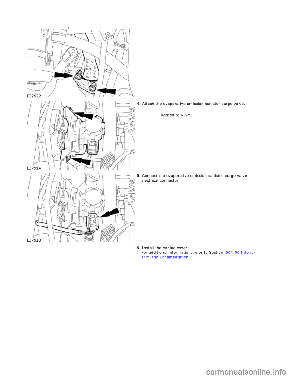
4.
Att
ach the evaporative emission canister purge valve.
1. Tighten to 6 Nm.
5. Conne
ct the evaporative emission canister purge valve
electrical connector.
6. Install the engine cover.
For additional informat ion, refer to Section 501
-0
5 Interior
Trim and Ornamen
tation
.
Page 1478 of 2490

Automatic Transmission/Transaxle External Controls - 4.0L NA V8 -
AJ27/3.2L NA V8 - AJ26 - Brake Shift Interlock Actuator Adjustment
General Procedures
1. Disconnect battery ground cable.
Remove the battery cover.
2. Remove the J-gate surround, Section 501-05.
3. Remove the console finisher ve neer panel, Section 501-12.
4. Remove the interlock soleno id actuating lever cover.
5. Move the shift lever to N.
Operate the gearshift interlock latch manually to release
the selector lever from P .
6. NOTE: Assistance from anot her person is required.
Adjust the gearshift interlock solenoid. 1. Slacken the solenoid fixings.
2. Hold the selector lever midway between P and R .
3. Move the solenoid rearwards, against spring pressure, to take up the free play.
4. Tighten the soleno id securing nuts.
5. Ensure that the interloc k actuating lever has no free
play with the selector lever midway between P and
Page 1482 of 2490

Automatic Transmission/Transaxle External Controls - 4.0L NA V8 -
AJ27/3.2L NA V8 - AJ 26 - Selector Lever Cable Adjustment
General Procedures
1. Disconnect battery ground cable.
Remove the battery cover.
2. Position the shift to N.
3. Remove the J-gate surround, Section 501-05.
4. Remove the console finisher ve neer panel, Section 501-12.
5. Remove the center console assembly, Section 501-12.
6. Slacken the selector cable locking nuts away from the
abutment.
7. Raise the vehicle for access.
8. Verify the transmission selector position ( N )
1. At the transmission, detach the inner cable from the selector lever.
2. With the lever moved fully rearward, push the lever forward two detents to achieve N.
3. Reconnect the inner cable.
9. From inside the vehicle.
10. NOTE: When setting the selector cable, ensure that the
transmission selector does not move from the N position.
Adjust the selector cable. 1. Position the shift in the N detent
2. Adjust the nuts to lock against the bracket without
Page 1484 of 2490
Automatic Transmission/Transaxle External Controls - 4.0L NA V8 -
AJ27/3.2L NA V8 - AJ26 - Br ake Shift Interlock Actuator
Removal and Installation
Removal
Installation
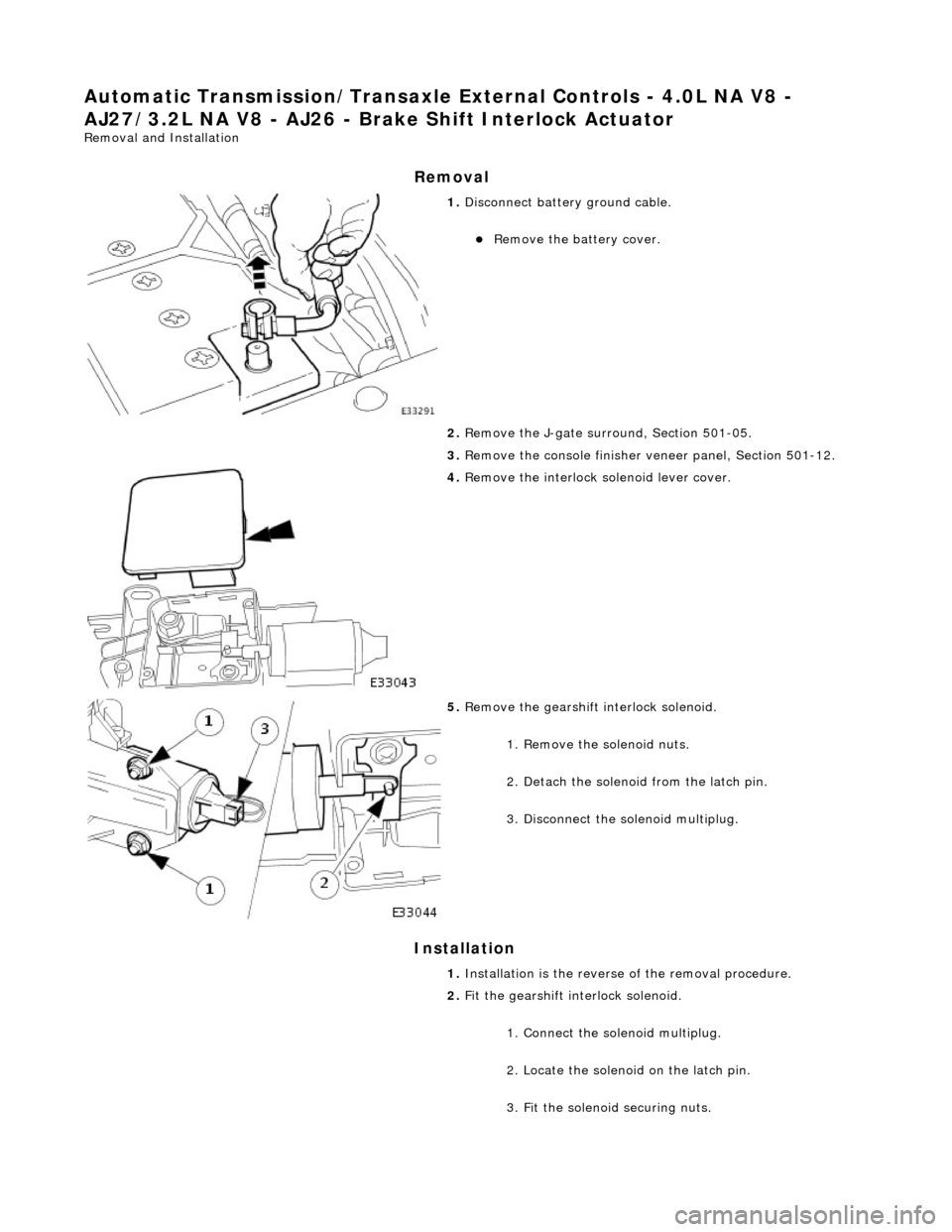
1. Disconnect battery ground cable.
Remove the battery cover.
2. Remove the J-gate surround, Section 501-05.
3. Remove the console finisher ve neer panel, Section 501-12.
4. Remove the interlock so lenoid lever cover.
5. Remove the gearshift interlock solenoid.
1. Remove the solenoid nuts.
2. Detach the solenoid from the latch pin.
3. Disconnect the solenoid multiplug.
1. Installation is th e reverse of the re moval procedure.
2. Fit the gearshift interlock solenoid.
1. Connect the solenoid multiplug.
2. Locate the solenoid on the latch pin.
3. Fit the solenoid securing nuts.
Page 1487 of 2490

Automatic Transmission/Transaxle External Controls - 4.0L NA V8 -
AJ27/3.2L NA V8 - AJ 26 - Selector Lever Cable and Bracket
Removal and Installation
Removal
1. Position the selector to N.
2. Remove the J-gate surround, Section 501-05.
3. Remove the console finisher ve neer panel, Section 501-12.
4. Remove the center console assembly, Section 501-12.
5. Raise the vehicle for access.
6. Detach the selector cable from the transmission unit.
1. Remove the cable inner to selector lever nut.
2. Remove the cable to transmission casing fixings.
7. Reposition the selector cable.
8. Remove the LH front seat, Section 501-10.
9. Reposition the LH floo r carpet for access.
10. Remove the selector cable to tunnel clip tie strap.
11. Detach the selector cable from the gear shift assembly.
1. Remove the inner cable to shift lever nut.
2. Slacken the outer cable locknuts.
Page 1491 of 2490
Automatic Transmission/Transaxle External Controls - 4.0L NA V8 -
AJ27/3.2L NA V8 - AJ 26 - Selector Lever Indicator Assembly
Removal and Installation
Removal
Installation
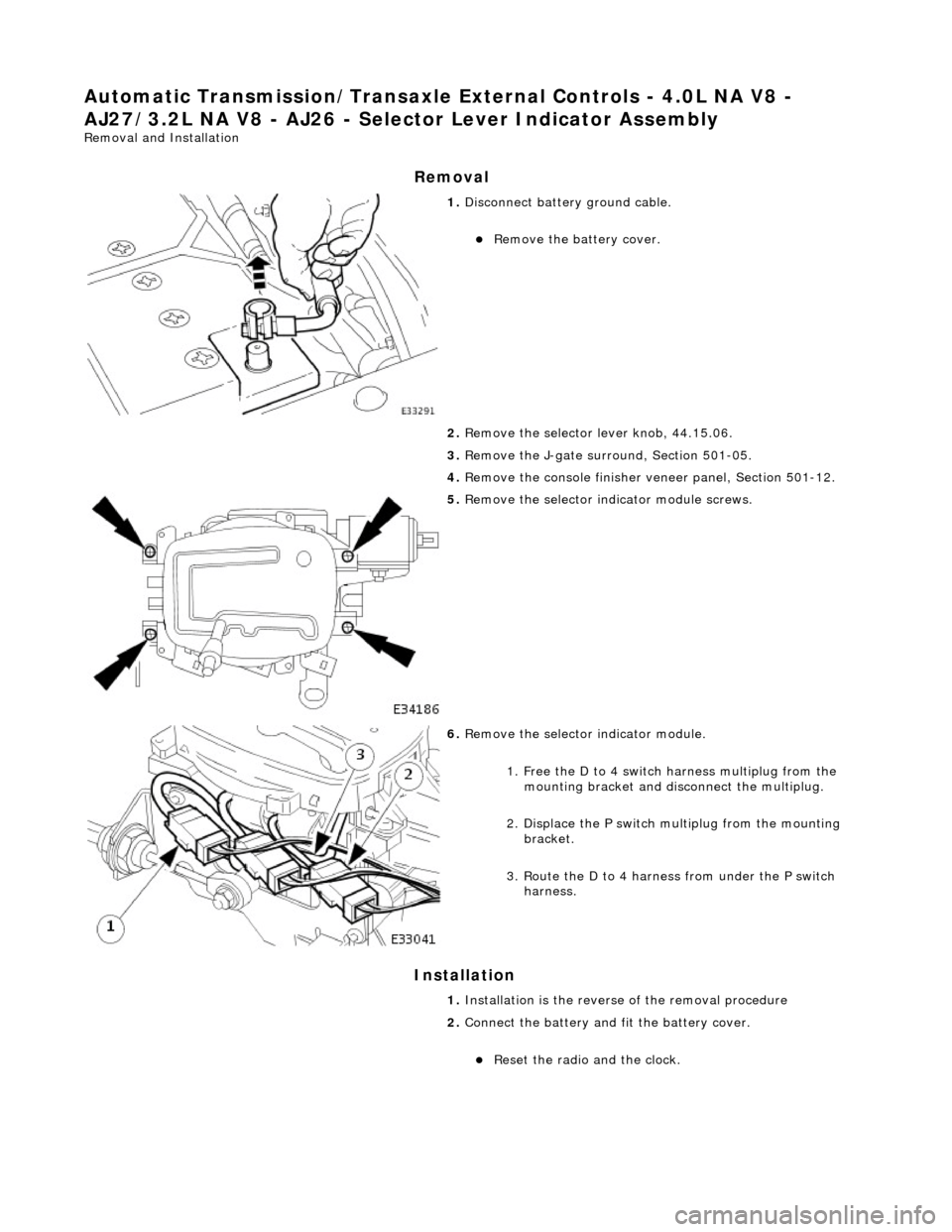
1. Disconnect battery ground cable.
Remove the battery cover.
2. Remove the selector lever knob, 44.15.06.
3. Remove the J-gate surround, Section 501-05.
4. Remove the console finisher ve neer panel, Section 501-12.
5. Remove the selector indicator module screws.
6. Remove the selector indicator module.
1. Free the D to 4 switch harness multiplug from the mounting bracket and disc onnect the multiplug.
2. Displace the P switch multiplug from the mounting bracket.
3. Route the D to 4 harnes s from under the P switch
harness.
1. Installation is the revers e of the removal procedure
2. Connect the battery and fit the battery cover.
Reset the radio and the clock.
Page 1495 of 2490

Automatic Transmission/Transaxle External Controls - 4.0L NA V8 -
AJ27/3.2L NA V8 - AJ26 - Selector Lever Assembly
Disassembly and Assembly
1. Disconnect battery ground cable.
Remove the battery cover.
2. Remove the shift le ver knob, 44.15.06.
3. Remove the J-gate surround, Section 501-05.
4. Remove the console finisher ve neer panel, Section 501-12.
5. Remove the center console assembly, Section 501-12.
6. Remove the indicator module, 44.15.14.
7. Detach the selector cable from the gear shift assembly.
1. Remove the inner cable to selector lever nut.
2. Slacken one outer cable locknut, keeping one positioned for reference on reassembly.
8. Remove the gear shift assembly.
Remove the four fixings.
9. Remove the slide plate.
Remove the four screws.