AF sensors JAGUAR X308 1998 2.G Owner's Guide
[x] Cancel search | Manufacturer: JAGUAR, Model Year: 1998, Model line: X308, Model: JAGUAR X308 1998 2.GPages: 2490, PDF Size: 69.81 MB
Page 1226 of 2490
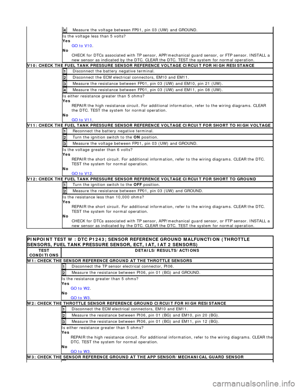
Measure the voltage between FP 01
, pin 03 (UW) and GROUND.
4
Is th
e volt
age less than 5 volts?
Yes GO to V10
.
No
CHECK
for DTCs associated with
TP sensor, APP/mechanical guard sensor, or FTP sensor. INSTALL a
new sensor as indicated by the DTC. CLEAR the DTC. TEST the system for normal operation.
V
10: CHECK
THE FUEL TANK PRESSURE SENSOR
REFERENCE VOLTAGE CIRCUIT FOR HIGH RESISTANCE
Disc
onnect the battery negative terminal.
1
D
i
sconnect the ECM electrical connectors, EM10 and EM11.
2
Measure t
he resistance between FP01,
pin 03 (UW) and EM10, pin 21 (UW).
3
Measure t
he resistance between FP01,
pin 03 (UW) and EM11, pin 08 (UW).
4
Is either resistance greater
than 5 ohms?
Yes REPAIR the high resistance circui t. For additional information, refer to the wiring diagrams. CLEAR
the DTC. TEST the system for normal operation.
No GO to V11
.
V11: CHECK
THE FUEL TANK PRESSURE SENSOR REFE
RENCE VOLTAGE CIRCUIT FOR SHORT TO HIGH VOLTAGE
Re
connect the battery negative terminal.
1
Turn the ignition swi
t
ch to the ON
position.
2
Measure the voltage between FP 01
, pin 03 (UW) and GROUND.
3
Is th
e volt
age greater than 6 volts?
Yes REPAIR the short circuit. For addi tional information, refer to the wiring diagrams. CLEAR the DTC.
TEST the system for normal operation.
No GO to V12
.
V12: CHECK
THE FUEL TANK PRESSURE SENSOR
REFERENCE VOLTAGE CIRCUIT FOR SHORT TO GROUND
Turn the ignition swit
ch to the OFF
position.
1
Measure t
he resistance between
FP01, pin 03 (UW) and GROUND.
2
Is t
he resistance less than 10,000 ohms?
Yes REPAIR the short circuit. For addi tional information, refer to the wiring diagrams. CLEAR the DTC.
TEST the system for normal operation.
No CHECK for DTCs associated with TP sensor, APP/mechanical guard sensor, or FTP sensor. INSTALL a
new sensor as indicated by the DTC. CLEAR the DTC. TEST the system for normal operation.
PI
NPOINT TEST W : DTC P1243; SENSOR RE
FERENCE GROUND MALFUNCTION (THROTTLE
SENSORS, FUEL TANK PRESSURE SENSOR, ECT, IAT, IAT 2 SENSORS)
TE S
T
CONDITIONS
D E
TAILS/RESULTS/ACTIONS
W1: CHECK THE SENSO
R
REFERENCE
GROUND AT THE THROTTLE SENSORS
Disc
onne
ct the TP sensor electrical connector, PI06.
1
Meas
ure t
he resistance between PI06, pin 01 (BG) and GROUND.
2
Is th
e res
istance greater than 5 ohms?
Yes GO to W2
.
No
GO to W3
.
W2: CHECK TH
E THROTTLE SENSOR REFERENCE GROUND CIRCUIT FOR HIGH RESISTANCE
D
i
sconnect the ECM electrical connectors, EM10 and EM11.
1
Meas
ure t
he resistance between PI06,
pin 01 (BG) and EM10, pin 20 (BG).
2
Measure t
he resistance between PI06,
pin 01 (BG) and EM11, pin 12 (BG).
3
Is either resistance greater
than 5 ohms?
Yes REPAIR the high resistance circuit. For additional information, refer to the wiring diagrams. CLEAR the
DTC. TEST the system for normal operation.
No GO to W3
.
W3: CHECK THE SENSO R
REFERENCE GROUND AT
THE APP SENSOR/MECHANICAL GUARD SENSOR
Page 1267 of 2490
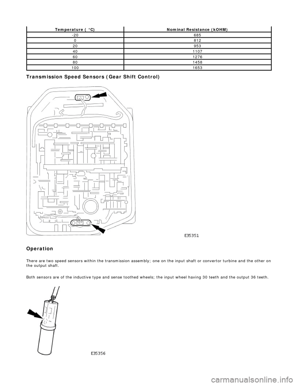
Transmission Speed Sensors (Gear Shift Control)
Operation
There are two speed sensors within the transmission assembly; one on the input shaft or convertor turbine and the other on the output shaft.
Both sensors are of the inductive type and sense toothed wheels; the input wheel having 30 teeth and the output 36 teeth.
Temperature ( °C)Nominal Resistance (kOHM)
-20685
0812
20953
401107
601276
801458
1001653
Page 1269 of 2490
2.2. Check on non-volatile diagnostic memory by wr iting a test pattern and then reading it back.
3. 3. Internal 'watchdog' hardware to check whether the TCM has crashed.
Transmission Control Module Supply Voltage
The TCM monitors battery and igni tion switched supply voltages.
A permanent supply is used to maintain a battery backed 'memor y'. Should this supply be cut, due to battery disconnection
perhaps, the 'adaptive shift' valu es will be lost. This will result in a small reduction in shift quality for a period until th e
adaptions are 're-learned'
The TCM will adopt 'limp home' mode as a result of the supply voltage being >16V or <7V with an engine speed >1600
rpm.
Should the ignition supply be >7V but <9V the TCM will hold the gear that it has currently selected. If after 2.5 seconds,
with the engine speed >1600 rpm, the voltage remains at this level, 'limp home' mode will be adopted. The 2.5 second
delay is built in to prevent reaction to a momentary voltage fluctuation.
Operation
CAUTION: Disconnection of the TCM and / or the vehicle batt ery will cause system adaptions to be lost; this may be
apparent by shift quality degradation. Fo llowing reconnection, a period of 'varied' driving will reinstate adaptions and thus
normal operation. Please ensure that the customer is made aware that the adaption period is variable and may occur after
handover, as the transmission re-learns the prevailing driving style.
• NOTE: Should the TCM fail, please ensure that the control housing cooling fan is operating correctly. Failure of the cooling
fan MUST be rectified before renewing the TCM and details of a fan fa ilure should accompany the returned TCM.
The TCM processes information received in both analogue and digital form, such as:
Transmission input speed Transmission output speed Throttle position Pedal demand Gear selector position Engine torque Engine speed Transmission oil temperature Mode switch
This information is then used by the TC M to control shift energy management and decide which shift program to implement
and which gear to select.
The TCM uses the various sensors and inpu ts to monitor the correct operation of the system an d is programmed to take
default action and inform the operator when a fault occurs.
Safety Functions
The safety functions are designed to safeguard against inappr opriate actions by the operator as well as against system
malfunctions. The system prevents reve rse gear from being engaged at high forward speeds and prevents manual
downshifting at excessive engine speeds; these functions are not operational in mechanical limp-home mode.
The TCM constantly monitors the transmissi on for faults. In the event of a problem the TCM will adopt a 'limp home' mode
in which only P R N D - (selector in D but only fourth gear is enabled) are available. The operator will be made aware of
certain faults by an in strument panel warning.
The electrical and diagnostic system has been designed such that system integrity is protected at all times, the safety
concept being based on th e following three points:
Page 1271 of 2490
Controller Area Network (CAN)
The TCM is an integral part of the CAN system which facilitates the interchange of real-time data between control modules
and sensors. Please see section 303- 14 for a full description of CAN.
OBDII Interface
Data concerning OBDII related transmission failures is stored in the ECM for access via the J1962 socket.
System Functions
Range Selection
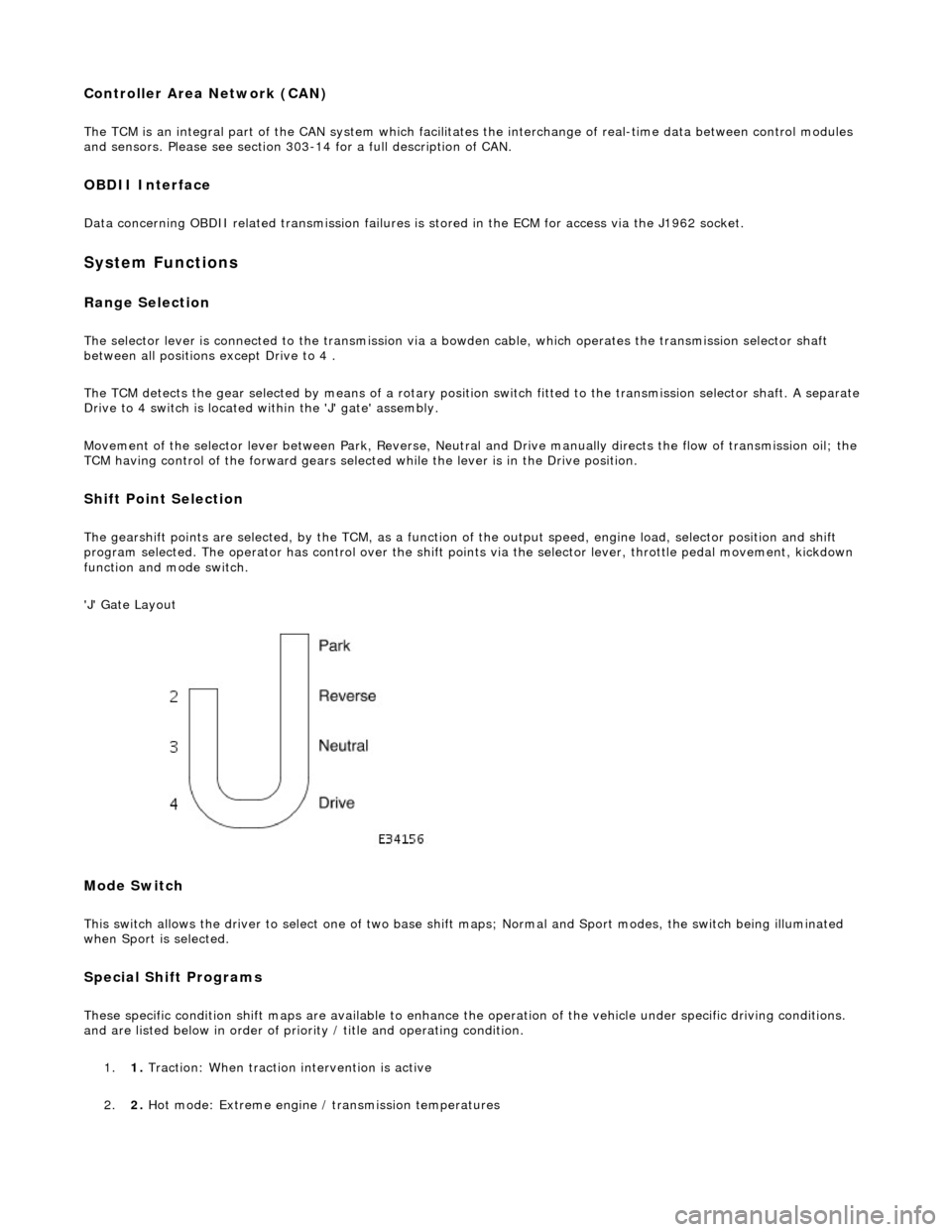
The selector lever is connected to the transmission via a bowden cable, which operates the transmission selector shaft
between all positions except Drive to 4 .
The TCM detects the gear selected by means of a rotary position switch fitted to the transmission selector shaft. A separate
Drive to 4 switch is located within the 'J' gate' assembly.
Movement of the selector lever between Park, Reverse, Neutral and Drive manually directs th e flow of transmission oil; the
TCM having control of the forward gears selected while the lever is in the Drive position.
Shift Point Selection
The gearshift points are selected, by the TCM, as a function of the output speed, engine load, selector position and shift
program selected. The operator has control over the shift points via the selector lever, throttle pedal movement, kickdown
function and mode switch.
'J' Gate Layout
Mode Switch
This switch allows the driver to select one of two base shift maps; Normal and Sport modes, the switch being illuminated
when Sport is selected.
Special Shift Programs
These specific condition shift maps are available to enhance the operation of the vehicle under specific driving conditions.
and are listed below in order of priority / title and operating condition.
1. 1. Traction: When traction intervention is active
2. 2. Hot mode: Extreme engine / transmission temperatures
Page 1390 of 2490
Stator, intermediate and output shafts. Three epicyclic geartrains. Six multi-disc clutch/brake packs. Two freewheels (One-way clutches). Hydraulic pump. Parking lock assembly. Electro-hydraulic control unit. Internal harness and 13 pin connector with bayonet lock.
Hydraulic pump
This engine driven pump is located at the front of the transmission casing and provides pressure for the hydraulic
functions.
Supplies fluid under pressure to the torq ue converter, geartrain, electro-hydraulic control unit and the lubrication
circuit.
Draws fluid from the fluid pa n below the transmission casing, through a filter.
Parking lock
This component prevents movement of th e vehicle by engaging a fixed pawl with the parking lock gear located on the
output shaft. The pawl is engaged by movi ng the gear selector lever to the park (P) position.
Electro-hydraulic control unit
This unit, mounted in the transmission lower case, converts signals, mechanical from the J-gate and electrical from the
TCM, into hydraulic functions.
The following components ar e assembled to the unit:
Selector valve. Shift plate. Control valve - modulating pressure. Control valve - shift pressure. Solenoid valve 1 <-> 2 and 4 <-> 5 shift. Solenoid valve 3 <-> 4 shift. Solenoid valve 2 <-> 3 shift. Solenoid valve - converter lock-up. Speed sensors (2). Temperature sensor.
Speed sensors
There are two speed sensors within the transmission assembly which provide input to the TCM. These inputs, when used in
conjunction with CAN data relative to engine speed (from ECM) and road speed (from ABS), are used to electronically
control the transmission.
Temperature sensor
The output from this sensor allows the TCM to compensate for the affect of fluid temperature on shift time and quality
Control Systems
Hydraulic Control
The selector valve is operated directly by the J-gate and directs fluid flow for P R N D.
Of the four solenoid valves, 3 control shifts and 1 controls converter lock-up. One control valve controls modulating pressure
and the other shift pressure.
Regulating valves are used to maintain/control pressure for lu brication, normal operating functions, and the supply to the
control valves and shift valves.
Page 1395 of 2490
and/or increased performance as appropriate.
Serial Communications Interfaces
Controller Area Network (CAN)
The TCM is an integral part of the CAN system which facilita tes the interchange of real-time data between control modules
and sensors; refer to 303-14 fo r a full description of CAN.
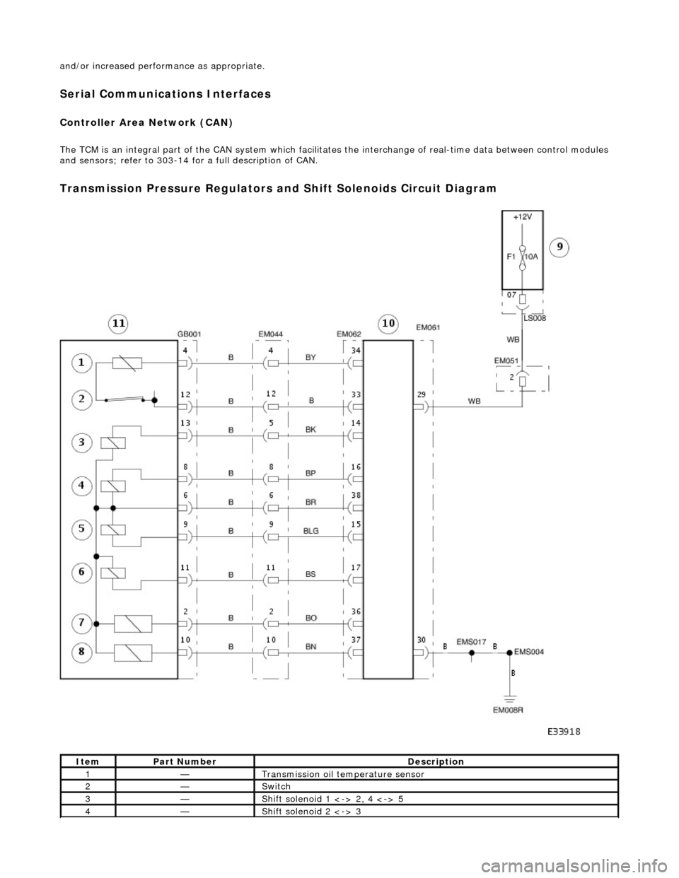
Transmission Pressure Regulators and Shift Solenoids Circuit Diagram
ItemPart NumberDescription
1—Transmission oil temperature sensor
2—Switch
3—Shift solenoid 1 <-> 2, 4 <-> 5
4—Shift solenoid 2 <-> 3
Page 1468 of 2490
Operation
• NOTE: The rotary position switch is NOT adjustable.
The position of the gear selector lever is detected by the range sensor; a system which consists of two sensors (switch
systems). 1. 1. The rotary position switch, which is located on the RH side of the transmission case and is coaxial with the
selector shaft.
2. 2. The D to 4 (micro) switch, which is mounted in the 'J gate' assembly.
When the selector is moved across the ga te to engage 4, or back from that side towards D the selector cable does not
move. In order that this change of state be registered by the TCM the D to 4 switch is incorporated.
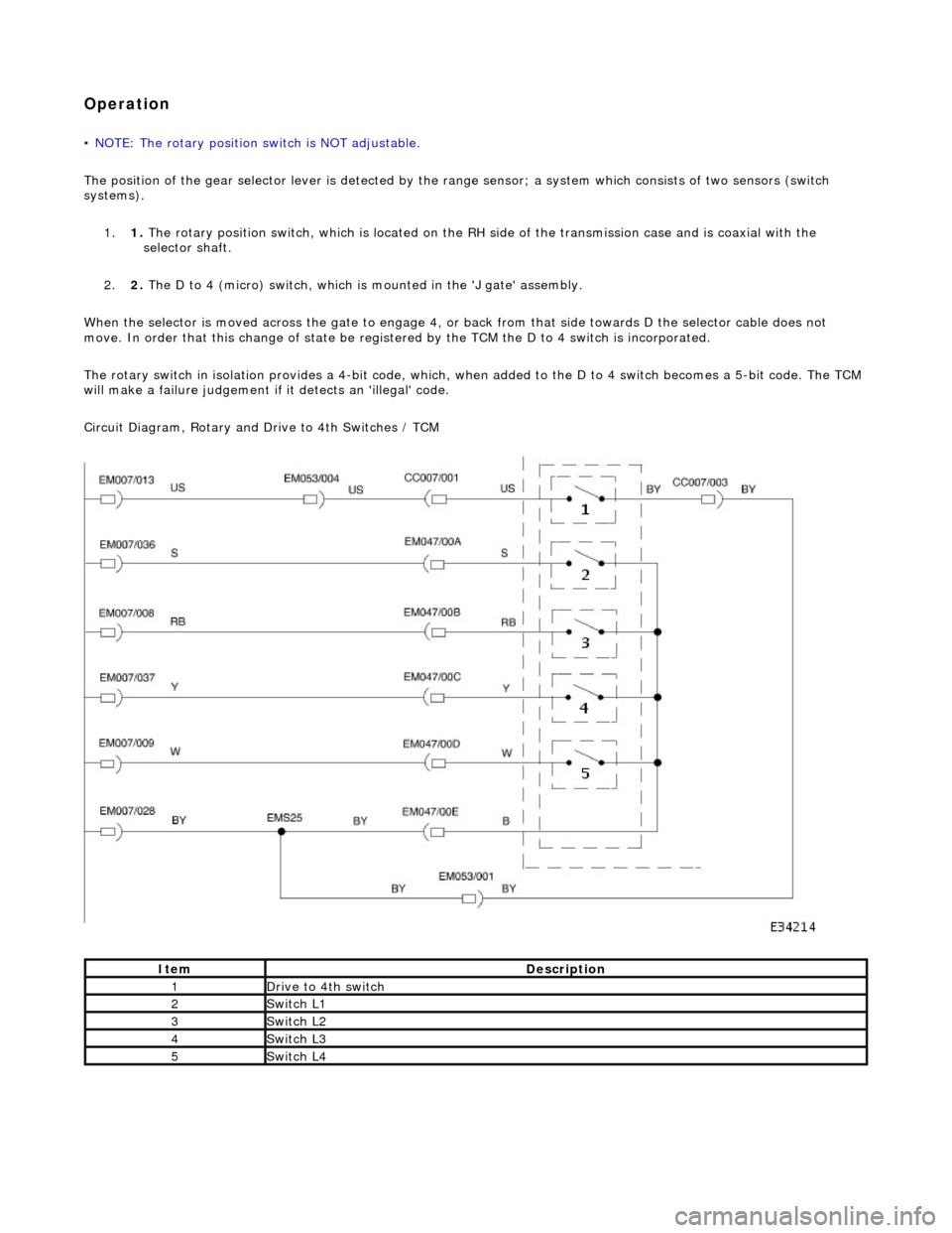
The rotary switch in isolation provides a 4-bit code, which, when added to the D to 4 switch becomes a 5-bit code. The TCM
will make a failure judgement if it detects an 'illegal' code.
Circuit Diagram, Rotary and Drive to 4th Switches / TCM
ItemDescription
1Drive to 4th switch
2Switch L1
3Switch L2
4Switch L3
5Switch L4
Page 1530 of 2490
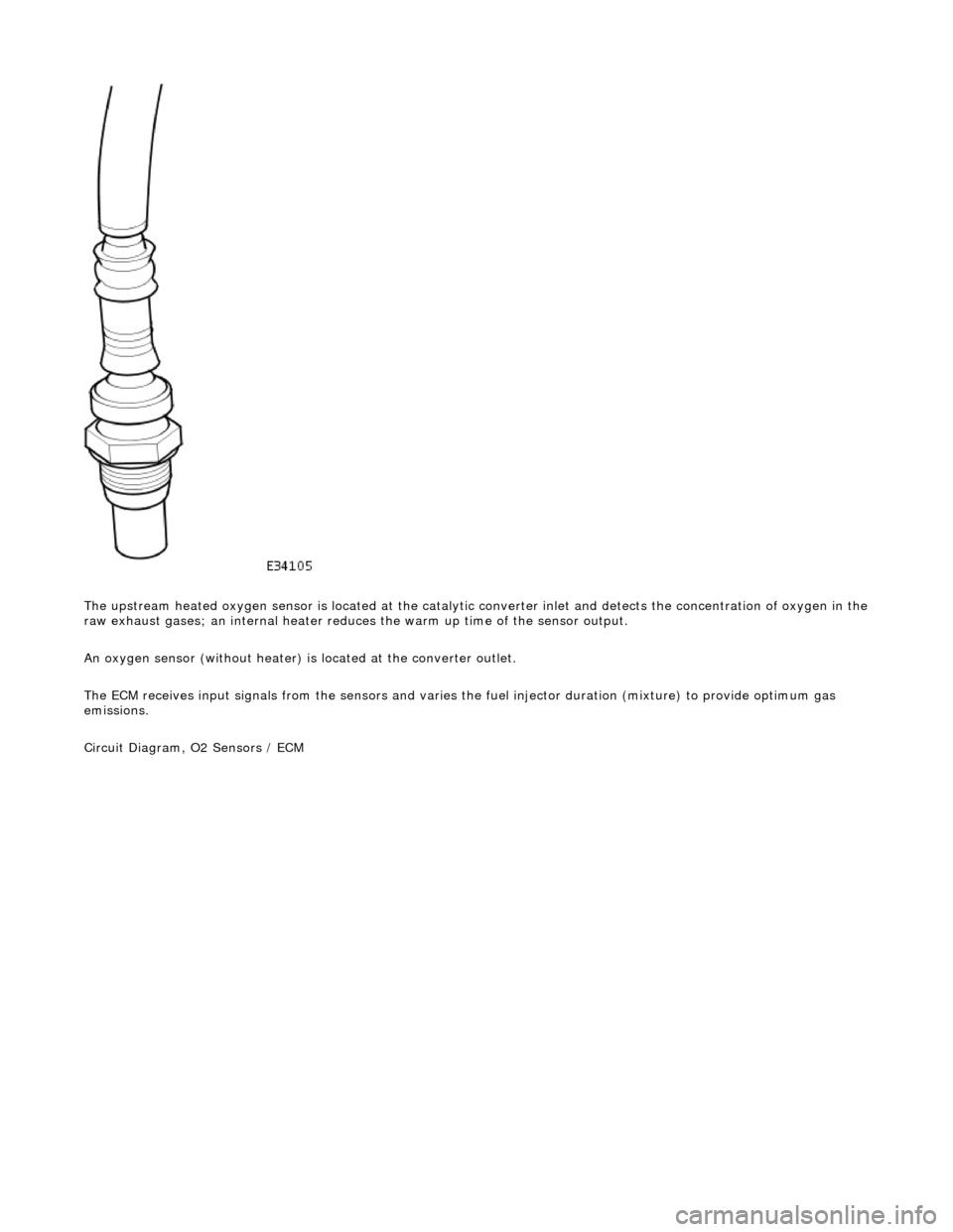
The upstream heated oxygen sensor is located at the catalytic converter inlet and detects the concentration of oxygen in the
raw exhaust gases; an internal heater reduces the warm up time of the sensor output.
An oxygen sensor (without heater) is located at the converter outlet.
The ECM receives input signals from the se nsors and varies the fuel injector duration (mixture) to provide optimum gas
emissions.
Circuit Diagram, O2 Sensors / ECM
Page 1743 of 2490
Accelerati
on Control - Accelerator Cable Adjustment
Gen
eral Procedures
1.
Load the Approved Jaguar Diagno stic System with power train
data logger.
2. Connect the Approved Jaguar Diag nostic System to the vehicle.
3. W
ith 'Disable Network Integrity Test - YES/ NO' displayed on
the screen select YES.
4. With new menu displayed on the screen, select ' Engine
Management'.
5. Turn the ignition to ON.
R
emove any previously selected data logger parameters.
6. On data logger select PPS11 an d PPS2 (Pedal demand sensors
1 and 2).
7. On Sedan models only, remove the bulkhead covers on both
sides and the engine compartment rear cover.
8. Cut, remove and discard the ra tchet strap which retains the
throttle cable to the abutment bracket.
9. Ensure there is no tension on the throttle cable by releasing
the throttle cable adjustment nut from the abutment bracket.
10. Record the voltages for both sensors, PPS11 and PPS2.
11. Partially insert the throttle cable adjustment nut into the
abutment bracket.
12. Recheck the voltages for both sensors, PPS11 and PPS2.
13. Where the voltages at step 12 are higher than the voltages
taken at step 10, contin ue to step 15 below.
14. Where the voltages at step 12 are the same as the voltages
taken at step 10, contin ue to step 16 below.
15. Rotate the adjustment nut clockwise (as viewed from the
front of the vehicle) until the same voltages are indicated as in
step 10. Continue to turn thro ugh a part revolution until the
sides of the nut are vertical. Tu rn through a further 90 degrees,
then fully insert the nut into the abutment bracket.
16. Rotate the adjustment nut anti-clockwise (as viewed from the
front of the vehicle) until the indicated voltage starts to
increase. Then rotate the nut clockwise through a part
revolution until the sides are ve rtical. Turn through a further 90
degrees, then fully insert the nut into the abutment bracket.
17. Fit a new ratchet strap to secure the throttle cable adjusting
nut to the abutment bracket.
18. Operate the throttle pedal through 20 full cycles to settle the
cable. Check the voltages now shown, remain the same as in
steps 15 and 16.
19. Check and where necessary adjust the kickdown switch. For
additional information, refer to Section 307
-05A Automatic Transmissi
on/Transaxle External Controls
Sectio
n
307
-05
B
Au
tomatic Transmission/Tra
nsaxle External Controls
.
20
.
On Sedan models only, refit the engine compartment rear
cover and the bulkhead co vers on both sides.
21. Switch the ignition OFF and disconnect the Approved Jaguar
Diagnostic System.
Page 1799 of 2490
Twin blower assemblies Center mounted evaporator, heater and air distribution unit Electric solenoid water valve controlled heating Electric water pump assembly Servo motor driven air distribution flaps Dedicated side glass defrost / demist vents External temperature sensor Motorised in-car aspirator Solar sensor
Electronic Control Panel
Liquid Crystal Display (LCD) Digital temperature display Manual fan speed level External temperature display Celsius / Fahrenheit selection Heated windshield switch (where fitted) Heated backlight switch Defrost switch Manual airflow distribution overrides (4) Access to self diagnostic system and error codes
Sensors
External ambient temperature sensor Motorized in-car aspirator Heater matrix temperature sensor Evaporator temperature sensor Solar sensor
These sensors feedback information to the Air Conditioning Control Module (A/CCM) which automatically adjusts air
temperature, airflow volume and distributi on from the air conditioning unit to maintain a stable passenger compartment
average temperature under changing weather conditions.
Major Components