engine oil JAGUAR X308 1998 2.G Owner's Guide
[x] Cancel search | Manufacturer: JAGUAR, Model Year: 1998, Model line: X308, Model: JAGUAR X308 1998 2.GPages: 2490, PDF Size: 69.81 MB
Page 632 of 2490

Installation
hea
d.
3. With assistance, remove the cylinder head.
34 . R
emove the cylinder head gasket.
1. Note how the gasket is installed and remove it.
2. Remove and discard the cloth, placed previously to absorb coolant spillage.
Wipe up any l e
aked coolant.
35. Remove the coolant drain tray from under the engine.
36. Remove and discard the gasket from the downpipe catalyst.
Cle
an the gasket faces of the catalyst and the exhaust manifold.
37. Clean cylinder head and cylinder block gasket faces.
Ensu
re that all threaded holes in the cylinder block face are clean and
free from oil.
Cl ean and
inspect the cylinder head bolts. They may be re-used on two
occasions. When re- used, each bolt head should be marked with one
dot from an automatic centre punch.
38. Clean and inspect all relevant components and mating faces.
1. CAUTIONS: If a replacement cylinder head is to be installed to a vehicle with VCT
the cylinder head must have the oil gallery blind rivet removed before
installation.
Make sure that all debris is removed from the cylinder head and cylinder
head oil gallery.
Vehicles fitted with VCT: Remove the blind rivet from the VCT oil gallary. • NOTE: The centre bore of the blind rivet is 6 mm diameter.
Page 633 of 2490

I
dentify the VCT oil supply gallery and the 8 mm blind rivet.
U
sing a suitable 3 mm punch release the centre of the blind rivet until
it is released from the outer part of the blind rivet.
U
sing a suitable extraction tool, remo
ve the remaining part of the blind
rivet.
2. Clean the component mating faces.
3.
Check cylinder head face for distortio
n, across the center and from corner
to corner.
4. For cylinder head face distortion data, refer to specifications.For additional
information, refer to: Specifications
(303
-00 Engine System - General
Information, Specifications).
5.
NOTE: For
cylinder head with
distortion above the
maximum allowance,
the cylinder head
material must be
measured.
Measure the
cylinder head
material.
Che
ck
measurement
from the
centre of the
exhaust
dowel to the
cylinder head
face as
shown.
If the
measurement
is less than
51.88 mm
the cylinder
head requires
replacement.
6.
Install a new gasket to the downpipe catalyst flange.
7. Install and align a new cylinder head gasket to the cylinder block face.
Page 644 of 2490
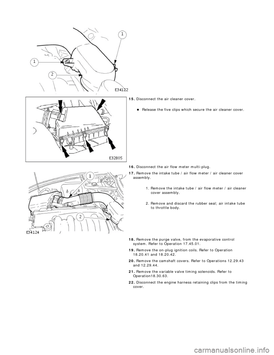
15. Di
sconnect the air cleaner cover.
R
e
lease the five clips which se
cure the air cleaner cover.
16. Disconnect the air flow meter multi-plug.
17 . R
emove the intake tube / air
flow meter / air cleaner cover
assembly.
1. Remove the intake tube / air flow meter / air cleaner
cover assembly.
2. Remove and discard the ru bber seal; air intake tube
to throttle body.
18. Remove the purge valve, fro m the evaporative control
system. Refer to Operation 17.45.01.
19. Remove the on-plug ignition coils. Refer to Operation
18.20.41 and 18.20.42.
20. Remove the camshaft covers. Refer to Operations 12.29.43
and 12.29.44.
21. Remove the variable valve ti ming solenoids. Refer to
Operation18.30.63.
22. Disconnect the engine harness retaining clips from the timing
cover.
Page 646 of 2490
In
stallation
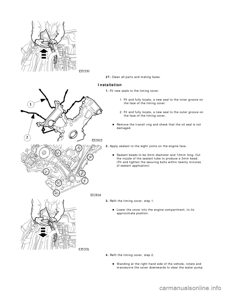
27
. Clean all parts and mating faces.
1. Fit ne
w seals to the timing cover.
1. Fit and fully locate, a new seal to the inner groove on the face of the timing cover.
2. Fit and fully locate, a new seal to the outer groove on the face of the timing cover.
Re
move the transit ring and check that the oil seal is not
damaged.
2. Appl y s
ealant to the eight joints on the engine face.
Sealant
beads to be 3mm di ameter an
d 12mm long. Cut
the nozzle of the sealant tube to produce a 3mm bead.
(Fit and tighten the securing bolts within twenty minutes
of sealant application)
3. Re
fit the timing cover, step 1.
Lo
wer th
e cover into the engine compartment, to its
approximate position.
4. Refit the timing cover, step 2.
Stan din
g at the right hand side
of the vehicle, rotate and
manoeuvre the cover downwards to clear the water pump
Page 653 of 2490
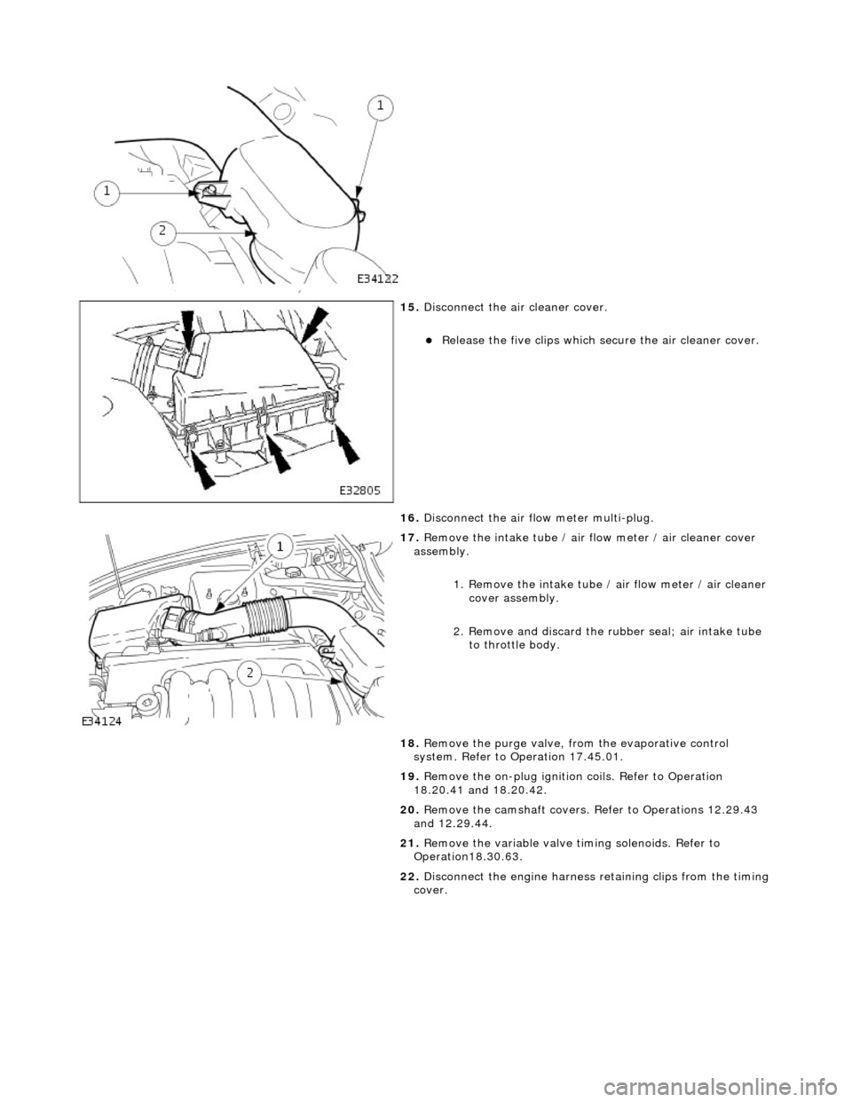
15
.
Disconnect the air cleaner cover.
R
elease the five clips which se
cure the air cleaner cover.
16. Disconnect the air flow meter multi-plug.
17
.
Remove the intake tube / air flow meter / air cleaner cover
assembly.
1. Remove the intake tube / air flow meter / air cleaner
cover assembly.
2. Remove and discard the ru bber seal; air intake tube
to throttle body.
18. Remove the purge valve, fro m the evaporative control
system. Refer to Operation 17.45.01.
19. Remove the on-plug ignition coils. Refer to Operation
18.20.41 and 18.20.42.
20. Remove the camshaft covers. Refer to Operations 12.29.43
and 12.29.44.
21. Remove the variable valve ti ming solenoids. Refer to
Operation18.30.63.
22. Disconnect the engine harness retaining clips from the timing
cover.
Page 655 of 2490
I
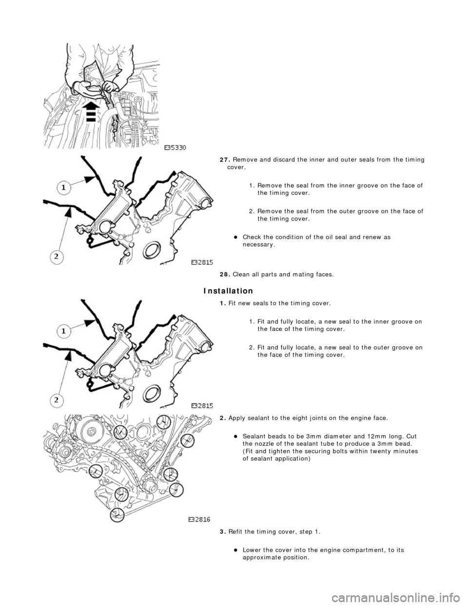
nstallation
27
.
Remove and discard the inner and outer seals from the timing
cover.
1. Remove the seal from the inner groove on the face of the timing cover.
2. Remove the seal from the outer groove on the face of
the timing cover.
Chec
k the condition of the oil seal and renew as
necessary.
28. Clean all parts and mating faces.
1. Fi
t new seals to the timing cover.
1. Fit and fully locate, a new seal to the inner groove on the face of the timing cover.
2. Fit and fully locate, a new seal to the outer groove on the face of the timing cover.
2. Appl
y sealant to the eight joints on the engine face.
Sealant
beads to be 3mm di
ameter and 12mm long. Cut
the nozzle of the sealant tube to produce a 3mm bead.
(Fit and tighten the securing bolts within twenty minutes
of sealant application)
3. Refit the timing cover, step 1.
Lo
wer the cover into the engine compartment, to its
approximate position.
Page 657 of 2490
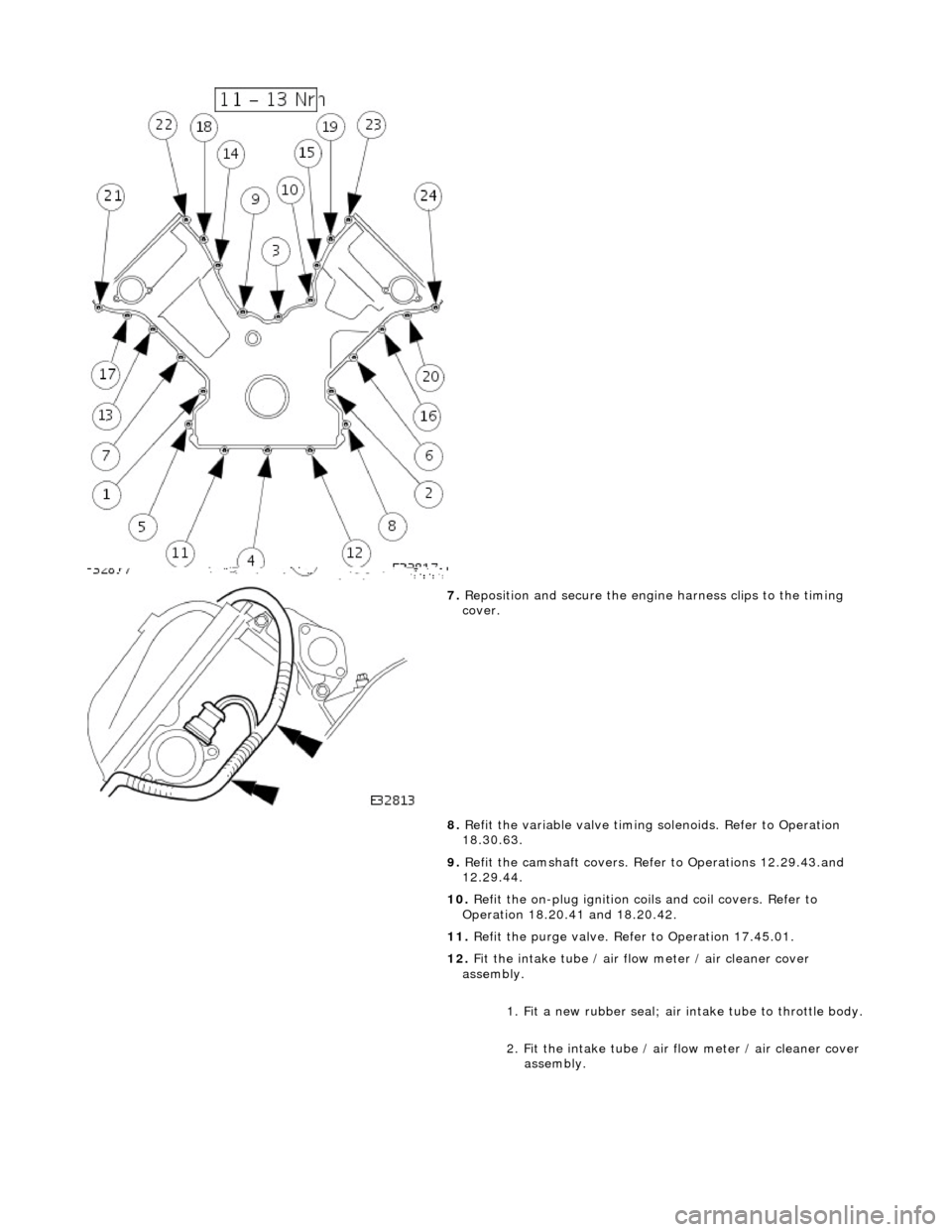
7. Reposition and secure the engine harness clips to the timing
cover.
8. Refit the variable valve timing solenoids. Refer to Operation
18.30.63.
9. Refit the camshaft covers. Refer to Operations 12.29.43.and
12.29.44.
10. Refit the on-plug ignition coils and coil covers. Refer to
Operation 18.20.41 and 18.20.42.
11. Refit the purge valve. Refer to Operation 17.45.01.
12. Fit the intake tube / air flow meter / air cleaner cover
assembly.
1. Fit a new rubber seal; air in take tube to throttle body.
2. Fit the intake tube / air flow meter / air cleaner cover
assembly.
Page 660 of 2490
Engine - Exhaust Camshaft LH
In-vehicle Repair
Removal
Installation
1. Open the engine compartment and fit paintwork protection
sheets.
2. Set the engine compartment cover to the service access
position.
3. Disconnect the batt ery ground cable.
Remove the battery cover.
4. Remove Exhaust Camshaft Sp rocket. Refer to Operation
12.65.74.
5. Remove the camshaft locking tool 303 - 530 (fitted for
previous operation).
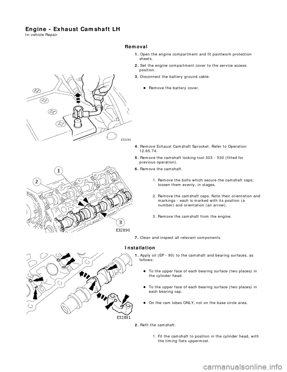
6. Remove the camshaft.
1. Remove the bolts which secure the camshaft caps; loosen them evenly, in stages.
2. Remove the camshaft caps. Note their orientation and
markings - each is marked with its position (a
number) and orientation (an arrow).
3. Remove the camshaft from the engine.
7. Clean and inspect all relevant components.
1. Apply oil (EP - 90) to the cams haft and bearing surfaces, as
follows:
To the upper face of each be aring surface (two places) in
the cylinder head.
To the upper face of each be aring surface (two places) in
each bearing cap.
On the cam lobes ONLY, not on the base circle area.
2. Refit the camshaft.
1. Fit the camshaft to position in the cylinder head, with the timing flats uppermost.
Page 662 of 2490
Engine - Exhaust Camshaft RH
In-vehicle Repair
Removal
Installation
1. Open the engine compartment and fit paintwork protection
sheets.
2. Set the engine compartment cover to the service access
position.
3. Disconnect the batt ery ground cable.
Remove the battery cover.
4. Remove Exhaust Camshaft Sp rocket. Refer to Operation
12.65.73.
5. Remove the camshaft locking tool 303 - 530 (fitted for
previous operation).
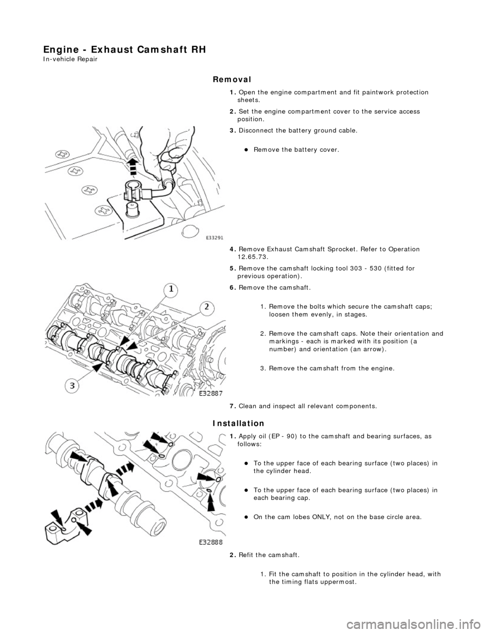
6. Remove the camshaft.
1. Remove the bolts which secure the camshaft caps; loosen them evenly, in stages.
2. Remove the camshaft caps. Note their orientation and
markings - each is marked with its position (a
number) and orientation (an arrow).
3. Remove the camshaft from the engine.
7. Clean and inspect all relevant components.
1. Apply oil (EP - 90) to the cams haft and bearing surfaces, as
follows:
To the upper face of each be aring surface (two places) in
the cylinder head.
To the upper face of each be aring surface (two places) in
each bearing cap.
On the cam lobes ONLY, not on the base circle area.
2. Refit the camshaft.
1. Fit the camshaft to position in the cylinder head, with the timing flats uppermost.
Page 700 of 2490
Engine - Intake Camshaft LH
In-vehicle Repair
Removal
Installation
1. Open the engine compartment and fit paintwork protection
sheets.
2. Set the engine compartment cover to the service access
position.
3. Disconnect the batt ery ground cable.
Remove the battery cover.
4. Remove the Timing Cover. Re fer to Operation 12.65.01.
5. Remove the VVT Unit from the B-Bank. Refer to Operation
12.65.71. This also includes the VVT Bush Carrier Assembly,
Primary Chain and Tensioner.
6. Remove the camshaft locking tool 303 - 530 (fitted for
previous operation).
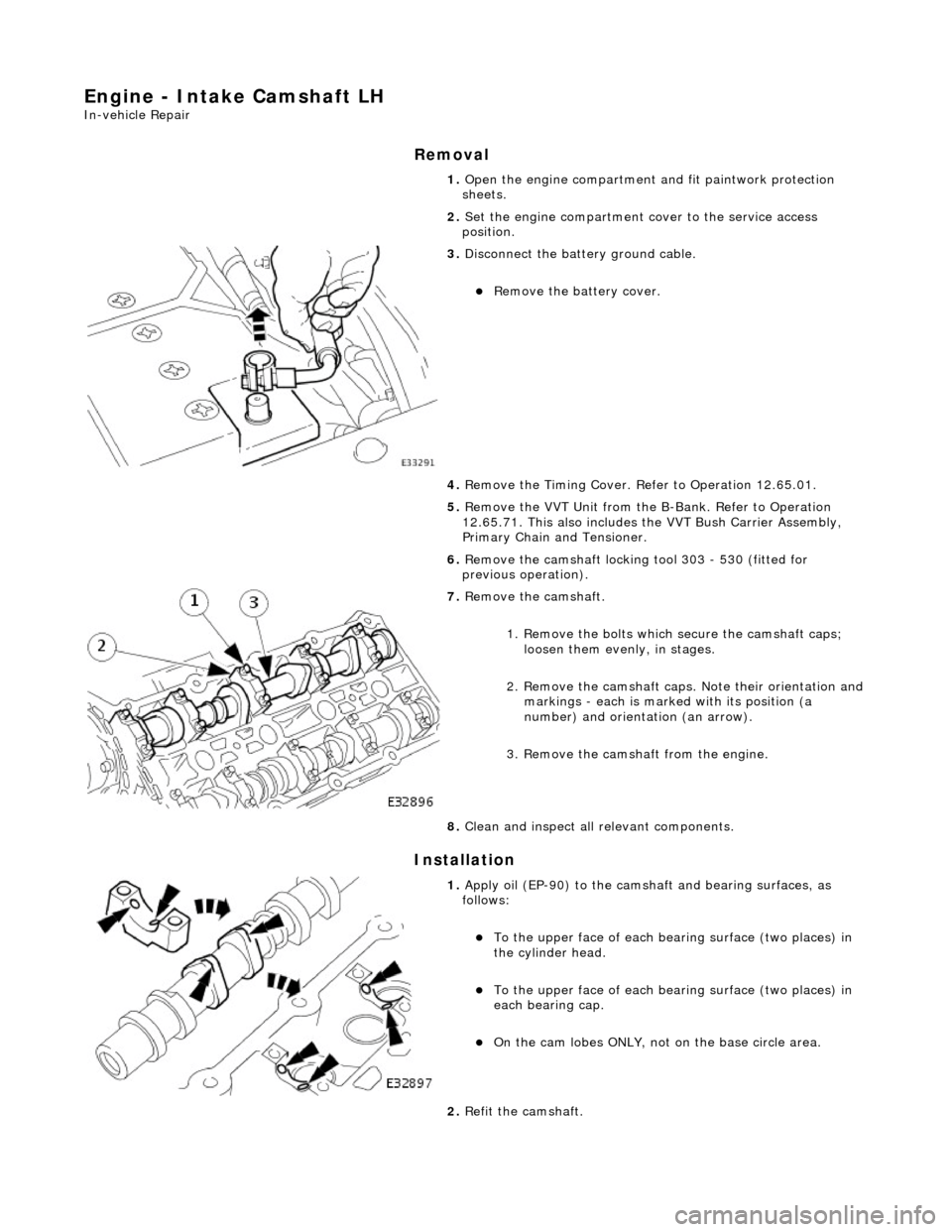
7. Remove the camshaft.
1. Remove the bolts which secure the camshaft caps; loosen them evenly, in stages.
2. Remove the camshaft caps. Note their orientation and
markings - each is marked with its position (a
number) and orientation (an arrow).
3. Remove the camshaft from the engine.
8. Clean and inspect all relevant components.
1. Apply oil (EP-90) to the camsha ft and bearing surfaces, as
follows:
To the upper face of each be aring surface (two places) in
the cylinder head.
To the upper face of each be aring surface (two places) in
each bearing cap.
On the cam lobes ONLY, not on the base circle area.
2. Refit the camshaft.