engine oil JAGUAR X308 1998 2.G Owner's Manual
[x] Cancel search | Manufacturer: JAGUAR, Model Year: 1998, Model line: X308, Model: JAGUAR X308 1998 2.GPages: 2490, PDF Size: 69.81 MB
Page 566 of 2490
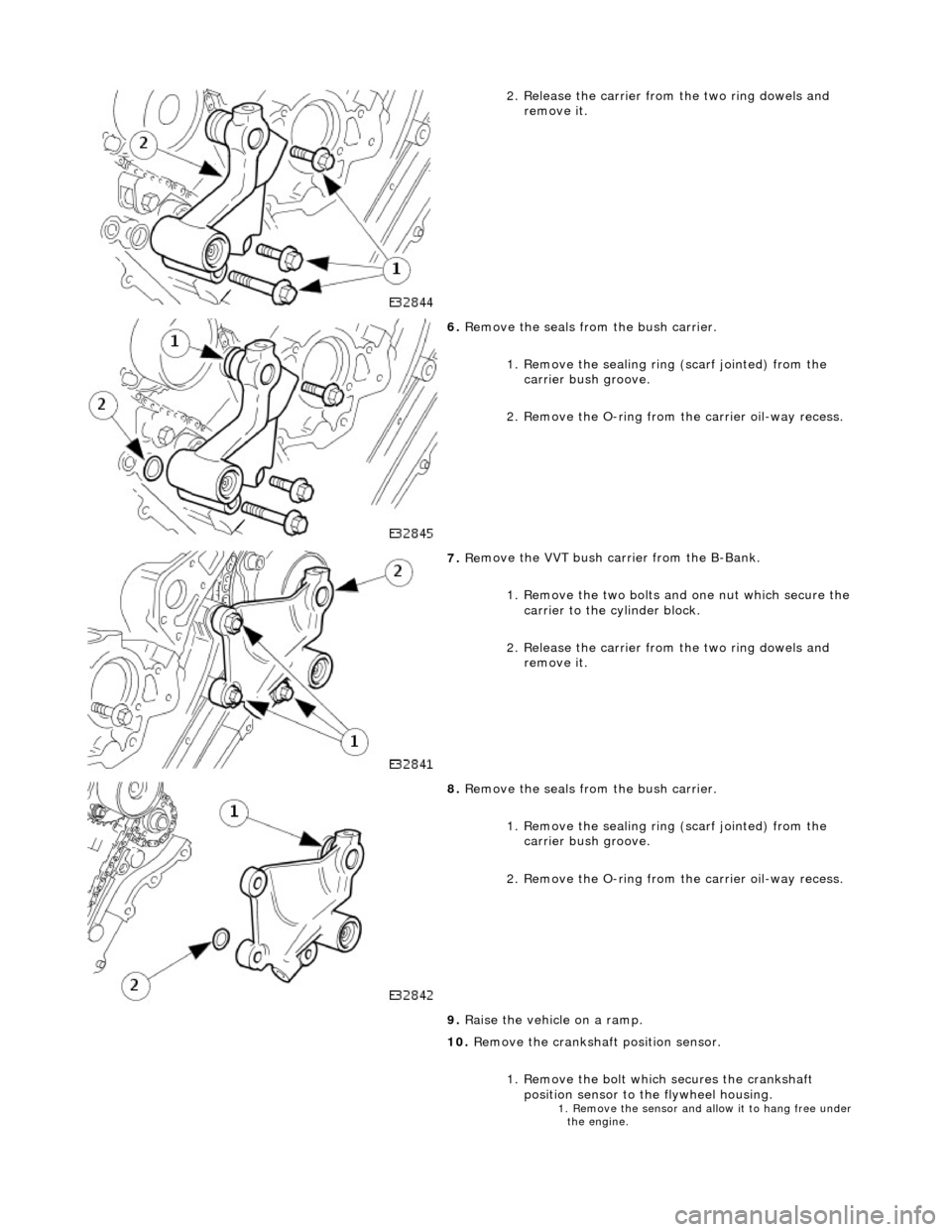
2.
Release the carrier from
the two ring dowels and
remove it.
6. Re
move the seals from the bush carrier.
1. Remove the sealing ring (scarf jointed) from the
carrier bush groove.
2. Remove the O-ring from the carrier oil-way recess.
7. Re
move the VVT bush carrier from the B-Bank.
1. Remove the two bolts and one nut which secure the carrier to the cylinder block.
2. Release the carrier from the two ring dowels and
remove it.
8. Re
move the seals from the bush carrier.
1. Remove the sealing ring (scarf jointed) from the
carrier bush groove.
2. Remove the O-ring from the carrier oil-way recess.
9. Raise the vehicle on a ramp.
10. Remove the crankshaft position sensor.
1. Remove the bolt which secures the crankshaft position sensor to the flywheel housing.
1. Re move
the sensor and allow it to hang free under
the engine.
Page 575 of 2490

2
. Fit a new O-ring to the carrier oil-way.
21
.
NOTE: Lubricate the seal (s carf jointed) and the bush.
Fit the VVT bush carrier to the cylinder block.
1. Fit the bush carrier assembly.
1. C
heck that the seals are in place and that the ring
dowels are engaged squa rely. Fully locate the
assembly as much as possible by hand pressure.
2
. Fit the three securing bolts. Tighten to 19 - 23 Nm.
22
.
Fit new seals to the VVT bush carrier, B-Bank.
1. Fit the new sealing ring (scarf jointed) to the carrier bush groove.
2. Fit a new O-ring to the carrier oil-way.
23
.
NOTE: Lubricate the seal (s carf jointed) and the bush.
Fit the VVT bush carrier to the cylinder block. 1. Fit the bush carrier assembly.
1. C
heck that the seals are in place and that the ring
dowels are engaged squa rely. Fully locate the
assembly as much as possible by hand pressure.
2
. Fit the two securing bolts and one nut. Tighten to 19
- 23 Nm.
24. Refit the Timing Cover. Refer to Operation 12.65.01 in this
Section.
25. Move the engine compartment cover from the service position
and connect the gas struts.
26. Remove the paint protection sheets and close the cover.
27. Connect the battery and fit the battery cover.
Re
fer to the Battery Reconnection Procedure 86.15.15.
Page 587 of 2490
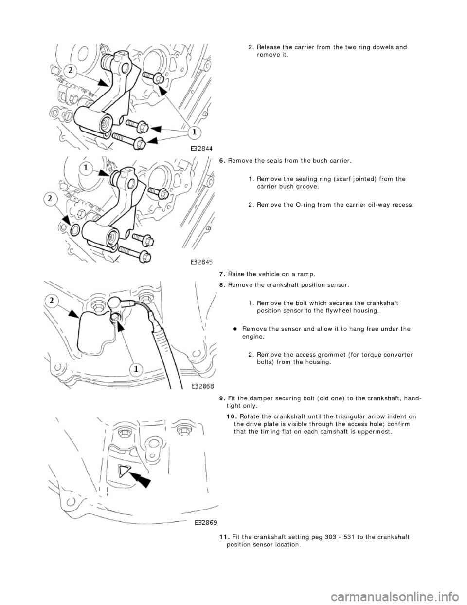
2
. Release the carrier from
the two ring dowels and
remove it.
6. R
emove the seals from the bush carrier.
1. Remove the sealing ring (scarf jointed) from the
carrier bush groove.
2. Remove the O-ring from the carrier oil-way recess.
7. Raise the vehicle on a ramp.
8. R
emove the crankshaft position sensor.
1. Remove the bolt which secures the crankshaft position sensor to the flywheel housing.
Remove the
sensor and allow
it to hang free under the
engine.
2. Remove the access grommet (for torque converter bolts) from the housing.
9. Fit the damper securing bolt (old one) to the crankshaft, hand-
tight only.
10
.
Rotate the crankshaft until the triangular arrow indent on
the drive plate is visible thro ugh the access hole; confirm
that the timing flat on ea ch camshaft is uppermost.
11. Fit the crankshaft setting peg 303 - 531 to the crankshaft
position sensor location.
Page 592 of 2490

2.
Fit a new O-ring to the carrier oil-way.
14. F
it the VVT bush carrier to the cylinder block.
Lubric
ate the seal (scarf
jointed) and the bush.
1. Fit the bush carrier assembly.
Check that th e seals are in pl ace an
d that the ring dowels
are engaged squarely. Fully locate the assembly as much
as possible by hand pressure.
2. Fit the three securing bolts. Tighten to 19-23 Nm.
15. Refit the Timing Cover. Refer to Operation 12.65.01 in this
Section.
16. Move the engine compartment cover from the service position
and connect the gas struts.
17. Remove the paint protection sheets and close the cover.
18. Connect the battery and fit the battery cover.
Refe
r to the Battery Reconnection Procedure in Section
414-01.
Page 605 of 2490

Engine - Crankshaft
Rear Seal4.0L
NA V8 - AJ27/3.2 L NA V8 - AJ26
In-v
ehicle Repair
Remov
al
S
pecial Tool(s)
Crankshaft Rear Oi
l Seal Remover /
Replacer.
303 - 538
1. Open the engine compartment and fit paint protection sheets.
2. Di
sconnect the batt
ery ground cable.
R
emove the battery cover.
3. Remove the transmission. Refer to Operation 44.20. 01 in
Section 307-01A.
4. Remove the drive plate. Refer to Operation 12.53.13.
5. F
it and align the seal removal tool 303 - 538 to the crankshaft.
1. Unscrew the two nuts towards the head of each bolt to allow the bolts to fit fully into the crankshaft.
2. Unscrew the center bolt until it is below the face of the main tool and position the tool to the rear of the
crankshaft.
3. Lightly tighten the two bolts so that they fully locate in the crankshaft.
6. Hold the tool against th
e cran
kshaft and lightly and evenly
tighten the two nuts to the face of the tool; to secure the tool
and to hold it parallel to the face of the crankshaft.
7. Secure the oil seal to the tool using the three self-tapping
Page 608 of 2490

Engine - Crankshaft Rear Seal4.0L SC V8 - AJ26
In-vehic
le Repair
Remov
a
l
S
p
ecial Tool(s)
Crankshaft Rear Oi
l Seal R
emover /
Replacer.
303 - 538
1. Open the engine compartment and fit paint protection sheets.
2. Disc
onnect the batt
ery ground cable.
Re
move the battery cover.
3. Remove the transmission. Refer to Operation 44.20. 01 in
Section 307-01B.
4. Remove the drive plat e. Refer to Operation (SC) 12.53.13.
5. Fi
t and align the seal removal tool 303 - 538 to the crankshaft.
1. Unscrew the two nuts towards the head of each bolt to allow the bolts to fit fully into the crankshaft.
2. Unscrew the center bolt until it is below the face of the main tool and position the tool to the rear of the
crankshaft.
3. Lightly tighten the two scre ws so that they fully locate
in the crankshaft.
6. Hold the tool against th e cr
an
kshaft and lightly and evenly
tighten the two nuts to the face of the tool; to secure the tool
and to hold it parallel to the face of the crankshaft.
7. Secure the oil seal to the tool using the three self-tapping
Page 611 of 2490
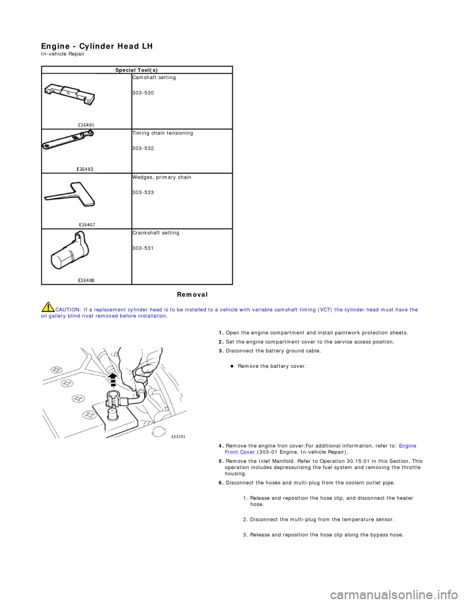
E
ngine - Cylinder Head LH
In-ve
hicle Repair
Remova
l
CAU
TION: If a replacement cylinder head is to be installed to a
vehicle with variable camshaft timing (VCT) the cylinder head m ust have the
oil gallery blind rivet removed before installation.
Spe
cial Tool(s)
Cams
haft setting
303-530
Ti
ming chain tensioning
303-532
Wedges, prim
ary chain
303-533
Cr
ankshaft setting
303-531
1.
Open the engine compartment and install paintwork protection sheets.
2. Set the engine compartment cover to the service access position.
3.
Disconnect the battery ground cable.
Re
move the battery cover.
4. Remove the engine fron cover.For additional information, refer to: Engine
Front Cover (303-01 Engi
ne, In-vehicle Repair).
5. Remove the Inlet Manifold. Refer to Operation 30.15.01 in this Section. This operation includes depressurising the fuel system and removing the throttle
housing.
6. Disconnect the hoses and multi-plug from the coolant outlet pipe.
1. Release and reposition the hose clip, and disconnect the heater hose.
2. Disconnect the multi-plug from the temperature sensor.
3. Release and reposition the hose clip along the bypass hose.
Page 621 of 2490

15
.
Connect the plug to the engine position sensor, at the rear of the cylinder
head.
16
.
Install the tappet and shim assemblies.
Lu
bricate each tappet assembly.
1. Install each tappet and shim asse mbly to its previously identified
position in the cylinder head.
17
.
Apply oil (EP-90) to the camshaft and bearing surfaces, as follows:
To th
e upper face of each bearing surface (two places) in the cylinder
head.
To th
e upper face of each bearing surface (two places) in each bearing
cap.
On
the cam lobes ONLY, not on the base circle area.
18. Install the camshafts.
1. Install the camshafts to position in the cylinder head, with the timing flats uppermost.
Page 625 of 2490
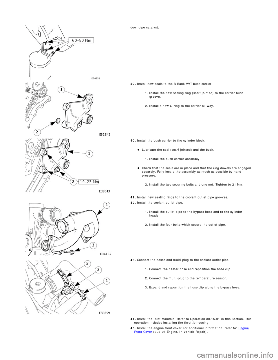
d
ownpipe catalyst.
39
.
Install new seals to the B-Bank VVT bush carrier.
1. Install the new sealing ring (scarf jointed) to the carrier bush groove.
2. Install a new O-ring to the carrier oil-way.
40
.
Install the bush carrier to the cylinder block.
Lu
bricate the seal (scarf
jointed) and the bush.
1. Install the bush carrier assembly.
Chec
k that the seals are
in place and that the ri ng dowels are engaged
squarely. Fully locate the assembly as much as possible by hand
pressure.
2. Install the two securing bolts and one nut. Tighten to 21 Nm.
41. Install new sealing rings to the coolant outlet pipe grooves.
42
.
Install the coolant outlet pipe.
1. Install the outlet pipe to the bypass hose and to the cylinder heads.
2. Install the four bolts which secure the outlet pipe.
43
.
Connect the hoses and multi-plug to the coolant outlet pipe.
1. Connect the heater hose and reposition the hose clip.
2. Connect the multi-plug to the temperature sensor.
3. Expand and reposition the hose clip along the bypass hose.
44. Install the Inlet Manifold. Refer to Operation 30.15.01 in this Section. This
operation includes installing the throttle housing.
45. Install the engine front cover.For additional information, refer to: Engine
Front Cover (303-01 Engi
ne, In-vehicle Repair).
Page 627 of 2490
E
ngine - Cylinder Head RH
In-ve
hicle Repair
Remova
l
CAU
TION: If a replacement cylinder head is to be installed to a
vehicle with variable camshaft timing (VCT) the cylinder head m ust have the
oil gallery blind rivet removed before installation.
Spe
cial Tool(s)
Cams
haft setting
303-530
Ti
ming chain tensioning
303-532
Wedges, prim
ary chain
303-533
Cr
ankshaft setting
303-531
1.
Open the engine compartment and install paintwork protection sheets.
2. Set the engine compartment cover to the service access position.
3.
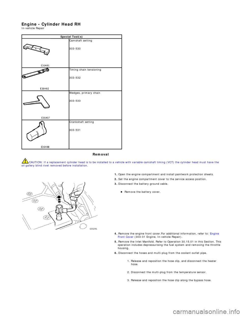
Disconnect the battery ground cable.
Re
move the battery cover.
4. Remove the engine front cover.For additional information, refer to: Engine
Front Cover (303-01 Engi
ne, In-vehicle Repair).
5. Remove the Inlet Manifold. Refer to Operation 30.15.01 in this Section. This operation includes depressurising the fuel system and removing the throttle
housing.
6. Disconnect the hoses and multi-plug from the coolant outlet pipe.
1. Release and reposition the hose clip, and disconnect the heater hose.
2. Disconnect the multi-plug from the temperature sensor.
3. Release and reposition the hose clip along the bypass hose.