power steering fluid JAGUAR X308 1998 2.G Owner's Guide
[x] Cancel search | Manufacturer: JAGUAR, Model Year: 1998, Model line: X308, Model: JAGUAR X308 1998 2.GPages: 2490, PDF Size: 69.81 MB
Page 2433 of 2490

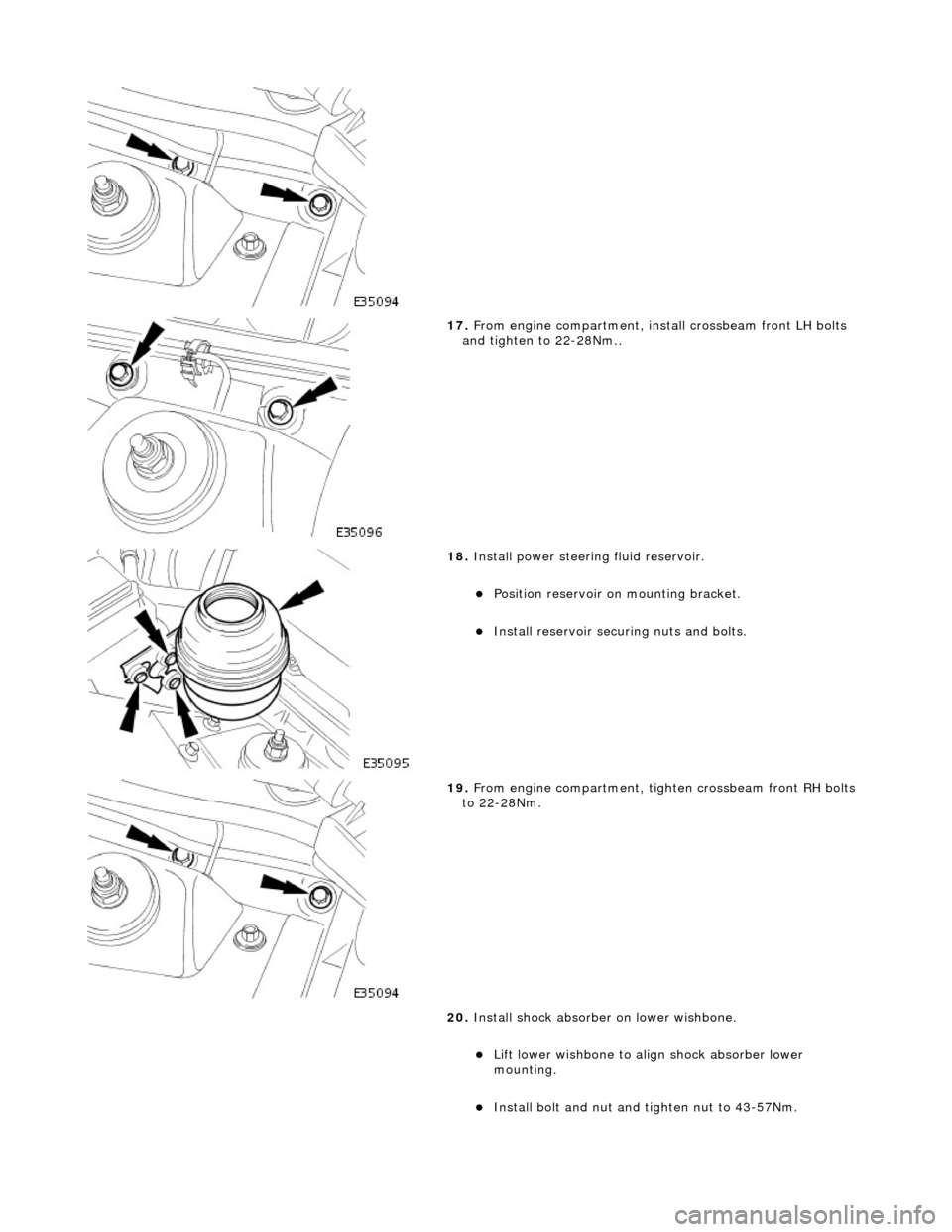
17. From engine compartment, install crossbeam front LH bolts
and tighten to 22-28Nm..
18. Install power steering fluid reservoir.
Position reservoir on mounting bracket.
Install reservoir securi ng nuts and bolts.
19. From engine compartment, tighten crossbeam front RH bolts
to 22-28Nm.
20. Install shock absorber on lower wishbone.
Lift lower wishbone to align shock absorber lower
mounting.
Install bolt and nut and ti ghten nut to 43-57Nm.
Page 2435 of 2490

26. Install power steering pi pes on pinion housing.
Remove blanks and install new 'O'-ring seals in pipe
connectors.
Apply power steering fluid to 'O' ring seals.
Remove blanking plugs from pinion housing ports.
Position pipes on pinion ports and seat 'O' rings.
27. Secure pipes to pinion housing.
Ensure pipes and retaining pl ate are correctly seated.
Install bolt and tighten to 9-12Nm.
28. Secure return pipe on steering rack.
1. Position pipe rubber support on steering rack.
2. Position pipe on support .
3. RHD vehicles. Position harness on pipe support rubber.
4. Secure pipe and harness to support with new tiestrap.
29. RHD vehicles. Using new tiestrap, secure harness to steering
rack.
Page 2445 of 2490

correctly seated in body locations.
3. Ensure that both engine hydram ounts are correctly seated in
crossbeam locations.
4. From engine compartment, install but do not tighten
crossbeam front RH bolts.
5. From engine compartment, install crossbeam front LH bolts
and tighten to 22-28Nm.
6. Install power steering fluid reservoir.
Position reservoir on mounting bracket.
Install reservoir securi ng nuts and bolts.
Page 2456 of 2490

correctly seated in body locations.
3. Ensure that both engine hydram ounts are correctly seated in
crossbeam locations.
4. From engine compartment, install but do not tighten
crossbeam front RH bolts.
5. From engine compartment, install crossbeam front LH bolts
and tighten to 22-28Nm.
6. Install power steering fluid reservoir.
Position reservoir on mounting bracket.
Install reservoir securi ng nuts and bolts.
Page 2463 of 2490

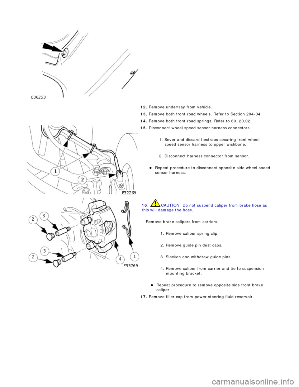
12. Remove undertray from vehicle.
13. Remove both front road wheels. Refer to Section 204-04.
14. Remove both front road springs. Refer to 60. 20.02.
15. Disconnect wheel speed sensor harness connectors.
1. Sever and discard tiestr aps securing front wheel
speed sensor harness to upper wishbone.
2. Disconnect harness connector from sensor.
Repeat procedure to disconnect opposite side wheel speed
sensor harness.
16. CAUTION: Do not suspend caliper from brake hose as
this will damage the hose.
Remove brake calipers from carriers.
1. Remove caliper spring clip.
2. Remove guide pin dust caps.
3. Slacken and withdraw guide pins.
4. Remove caliper from carrier and tie to suspension mounting bracket.
Repeat procedure to remove opposite side front brake
caliper.
17. Remove filler cap from power steering fluid reservoir.
Page 2465 of 2490

24. Drain power steering fluid.
Disconnect pipes and al low fluid to drain.
Remove and discard 'O'-ring seals from pipe connectors.
Fit blanking plugs to pipe connectors and pinion housing
ports.
25. Remove drain receptacle.
26. Remove pipe support from steering rack.
Release return pipe from support.
Remove support from rack.
27. Ensure that steering is in central position.
28. Release lower steering column from pinion shaft.
1. Remove lower steering co lumn securing nut and bolt.
Move column upwards to release it from pinion shaft.
29. Support weight of crossbeam.
Position a jack under crossbeam.
Page 2475 of 2490

22. Install power steering fluid reservoir.
Position reservoir on mounting bracket.
Install reservoir securi ng nuts and bolts.
23. From engine compartment, tighten crossbeam front RH bolts
to 22-28Nm.
24. Install shock absorber on lower wishbone.
Lift lower wishbone to align shock absorber lower
mounting.
Install bolt and nut and ti ghten nut to 43-57Nm.
Repeat procedure to install opposite side shock absorber.
25. Install lower steering column on pinion shaft.
Move column downwards to engage coupling splines on
pinion shaft.
1. Install nut and bolt and tighten to 22-28Nm.
Page 2476 of 2490

26. Lower and withdraw jack from crossbeam.
27. Release engine from support tool.
1. Slacken hook adjustment nuts until weight of engine is released.
2. Remove hooks from engine front lifting eyes.
3. Remove special tool 303- 021 from fender channel.
28. Install crossbeam to engine Hydramount bolts.
Install bolt securing Hydr amount to crossmember and
tighten to 22-28Nm.
Repeat procedure to install crossmember opposite side
securing bolt.
29. Position and connect harnes s to steering transducer.
RHD vehicles. Position steeri ng harness behind return
pipe.
Connect harness to transducer.
30. Install power steering pi pes on pinion housing.
Remove blanks and install new 'O'-ring seals in pipe
connectors.
Apply power steering fluid to 'O' ring seals.