lower JAGUAR X308 1998 2.G Workshop Manual
[x] Cancel search | Manufacturer: JAGUAR, Model Year: 1998, Model line: X308, Model: JAGUAR X308 1998 2.GPages: 2490, PDF Size: 69.81 MB
Page 2261 of 2490
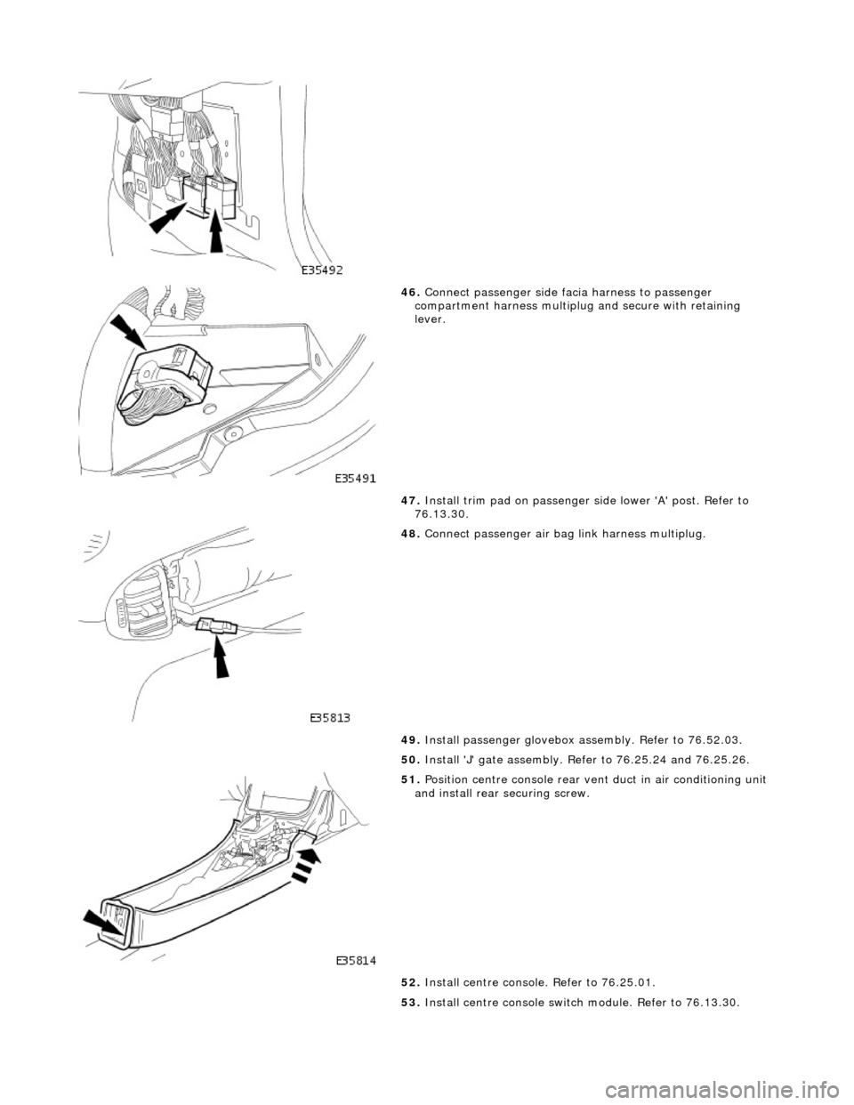
46. Connect passenger side facia harness to passenger
compartment harness multiplug and secure with retaining
lever.
47. Install trim pad on passenger side lower 'A' post. Refer to
76.13.30.
48. Connect passenger air bag link harness multiplug.
49. Install passenger glovebox assembly. Refer to 76.52.03.
50. Install 'J' gate assembly. Refer to 76.25.24 and 76.25.26.
51. Position centre console rear vent duct in air conditioning unit
and install rear securing screw.
52. Install centre console. Refer to 76.25.01.
53. Install centre console switch module. Refer to 76.13.30.
Page 2263 of 2490

64.
Position driver stowage bin in facia, install securing screw and fully seat trim.
65. Install trim pad on driver si de lower 'A' post. Refer to
76.13.30.
66. Install driver side unders cuttle. Refer to 76.46.11.
67. Install combined windshield wi per/washer switch and audible
warning speaker assembly. Refer to 86.65.42.
68. Install steering column upper cowl. Refer to 76.46.02.
69. Install steering column lower cowl. Refer to 76.46.03.
70. Install steering wheel. Refer to 211-04.
71. Install driver side airbag. Refer to 76.73.39.
Page 2266 of 2490

Instrument Panel and Console - Instrument Panel Lower Trim Panel
Removal and Installation
Removal
Installation
1.
Turn ignition switch to position 'II.'
2. Motor driver seat fully rearwards.
3. Turn ignition switch to position 'O.'
4. Slacken and remove the four underscuttle securing screws.
5. Remove and discard securing clips from screw locations.
6. Remove underscuttle from vehicle.
1. Fit new securing clips to screw locations.
2. Position and fully seat underscu ttle below fascia and fit and
tighten securing screws.
3. Return driver seat to original position.
Page 2267 of 2490

Instrument Panel and Console - Overhead Console
Removal and Installation
Removal
1. Remove battery cover and disconnect ground cable from
battery terminal. Refer to 86.15.19.
2. Open roof console sun glasses compartment.
3. Rotate fastener 1/4 turn to release console.
4. Lower console from roof and disconnect lighting module
harness multiplug and hands- free microphone harness
multiplug if telephone is fitted.
5. Release roof console from retaining clips and remove from
vehicle.
Page 2271 of 2490
Instrument Panel and Console - Steering Column Lower Shroud
Removal and Installation
Removal
Installation
1.
Move driver seat fully rearward.
2. Remove battery cover and disconnect ground cable from
battery terminal.Refer to 86.15.19.
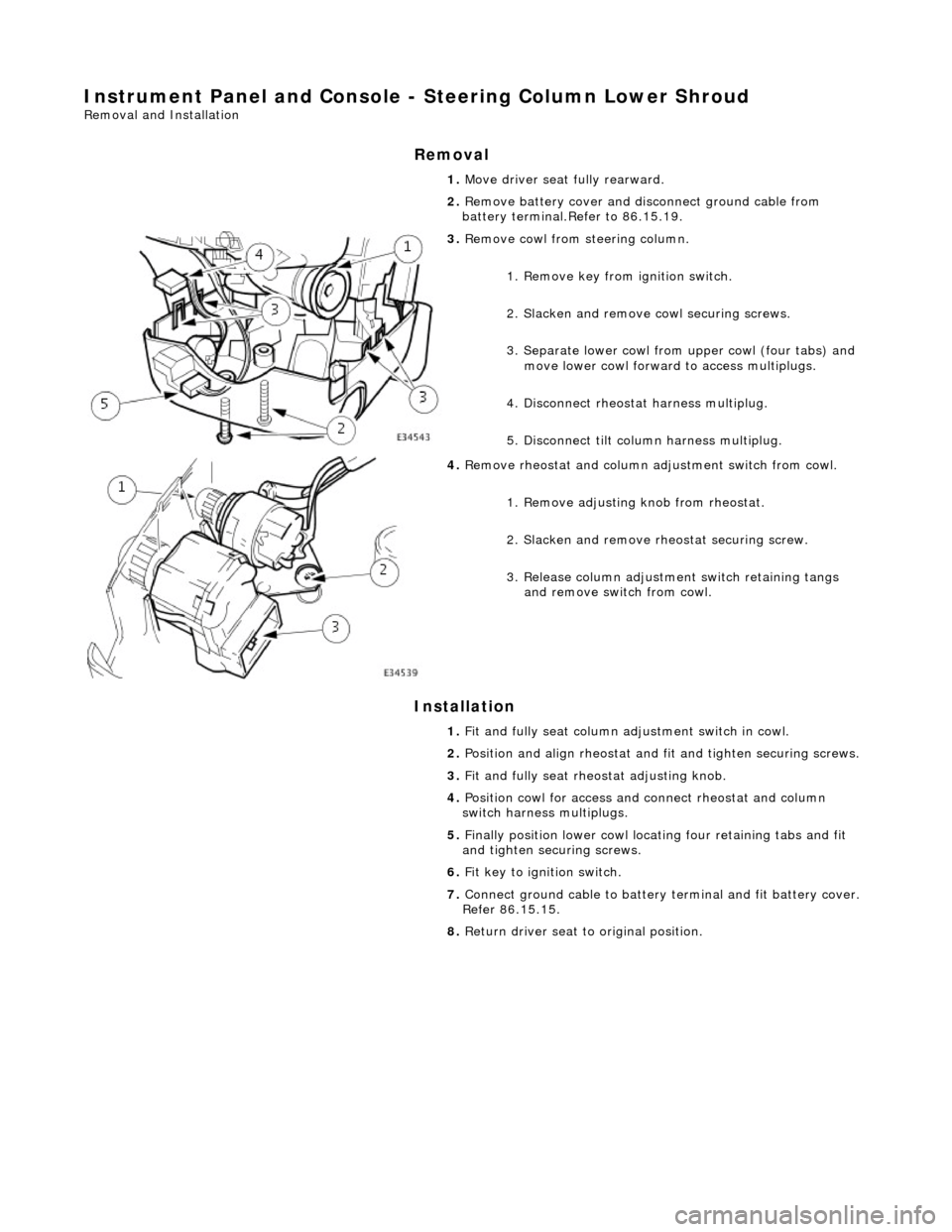
3. Remove cowl from steering column.
1. Remove key from ignition switch.
2. Slacken and remove cowl securing screws.
3. Separate lower cowl from upper cowl (four tabs) and move lower cowl forward to access multiplugs.
4. Disconnect rheostat harness multiplug.
5. Disconnect tilt column harness multiplug.
4. Remove rheostat and column adjustment switch from cowl.
1. Remove adjusting knob from rheostat.
2. Slacken and remove rh eostat securing screw.
3. Release column adjustment switch retaining tangs and remove switch from cowl.
1. Fit and fully seat column ad justment switch in cowl.
2. Position and align rheostat and fit and tighten securing screws.
3. Fit and fully seat rheo stat adjusting knob.
4. Position cowl for access and connect rheostat and column
switch harness multiplugs.
5. Finally position lower cowl locating four retaining tabs and fit
and tighten securing screws.
6. Fit key to ignition switch.
7. Connect ground cable to battery terminal and fit battery cover.
Refer 86.15.15.
8. Return driver seat to original position.
Page 2272 of 2490
Instrument Panel and Console - Steering Column Upper Shroud
Removal and Installation
Removal
Installation
1.
Move driver seat fully rearward.
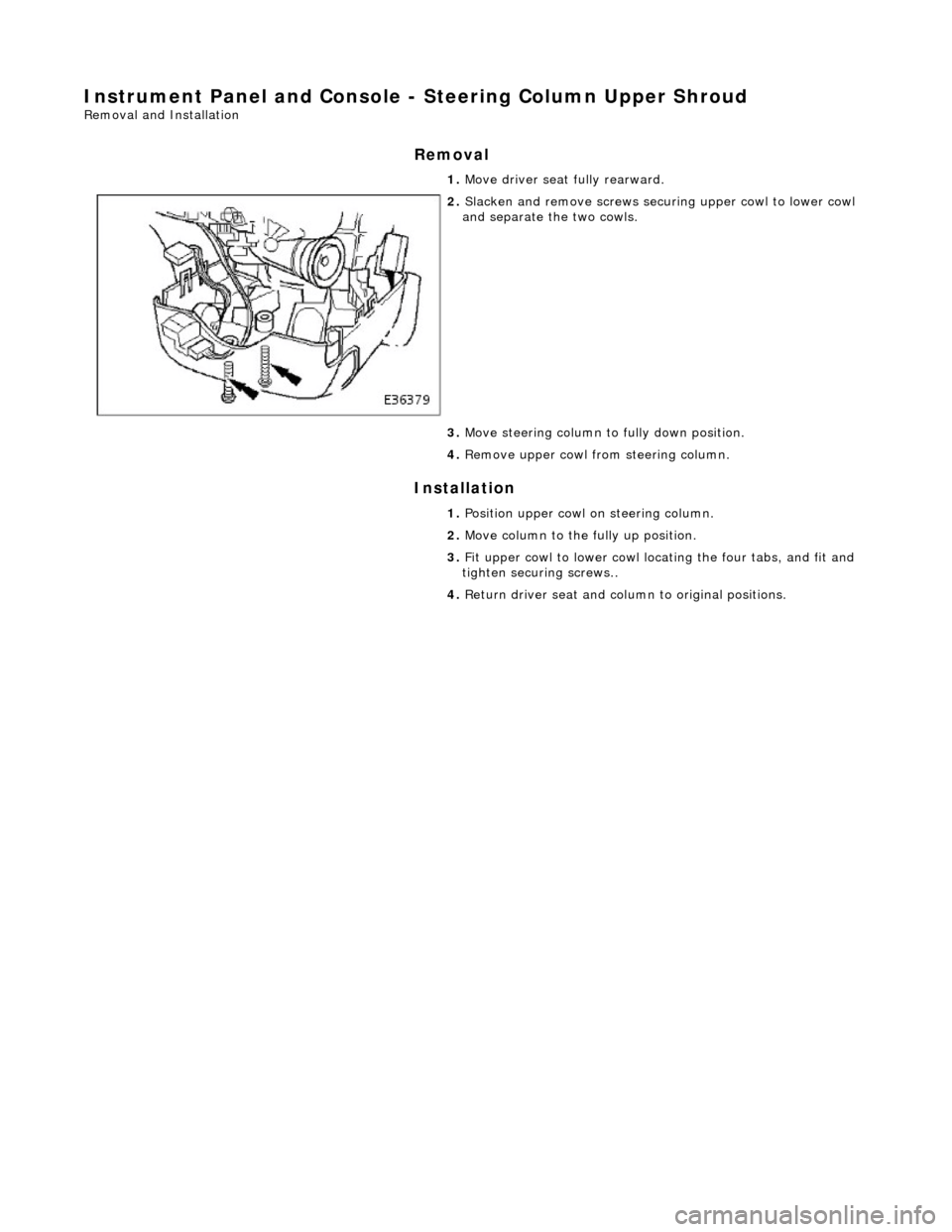
2. Slacken and remove screws securing upper cowl to lower cowl
and separate the two cowls.
3. Move steering column to fully down position.
4. Remove upper cowl fr om steering column.
1. Position upper cowl on steering column.
2. Move column to the fully up position.
3. Fit upper cowl to lower cowl locating the four tabs, and fit and
tighten securing screws..
4. Return driver seat and column to original positions.
Page 2277 of 2490
Handles, Locks, Latches and Entry Systems - Exterior Driver Door Handle
Removal and Installation
Removal
1. Motor door glass to fully up position.
2. Remove battery cover and disconnect ground cable from
battery terminal. Refer to 86.15.19.
3. Remove door casing veneer panel. Refer to 76.47.11.
4. Remove door casing for access. Refer to 76.34.01.
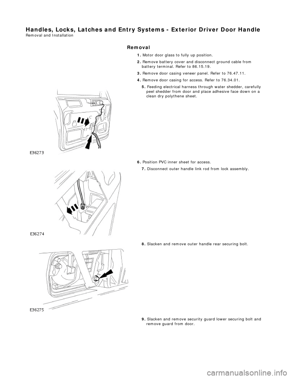
5. Feeding electrical harness thro ugh water shedder, carefully
peel shedder from door and pl ace adhesive face down on a
clean dry polythene sheet.
6. Position PVC inner sheet for access.
7. Disconnect outer handle link rod from lock assembly.
8. Slacken and remove outer handle rear securing bolt.
9. Slacken and remove security gu ard lower securing bolt and
remove guard from door.
Page 2279 of 2490

Installation
14. Slacken and remove lock barre l securing screw and remove
lock barrel from handle.
1. Align and fit lock barrel to door handle and fit and tighten
securing screw.
2. Fit link rods to door handle assembly.
3. Align and fit handle assembly to door
4. Position clamping plate inside door, and holding handle in
position, fit and tighten securing bolts.
5. Position barrel link rod on lock assembly and secure with
locking collar.
6. Check for satisfactory door handle operation.
7. Slacken and remove door handle rear securing bolt.
8. Position door lock security guard and fit and hand tighten lower
securing bolt.
9. Fit and tighten door handle rear /security guard upper securing
bolt.
10. Fully tighten security guard lower securing bolt.
11. Connect lock link rod to door handle.
12. Reposition PVC inner sheet.
13. Connect ground cable to battery terminal. Refer to 86.15.15.
14. Check for satisfactory operation of locking system
15. Disconnect ground cable from battery terminal. Refer to
86.15.15.
16. Ensure that shedder contact area of door is clean and dry.
17. Position water shedder at door and carefully pass harness
through.
18. Fit and firmly seat water shedder on door ensuring
satisfactory adhesion.
Page 2283 of 2490
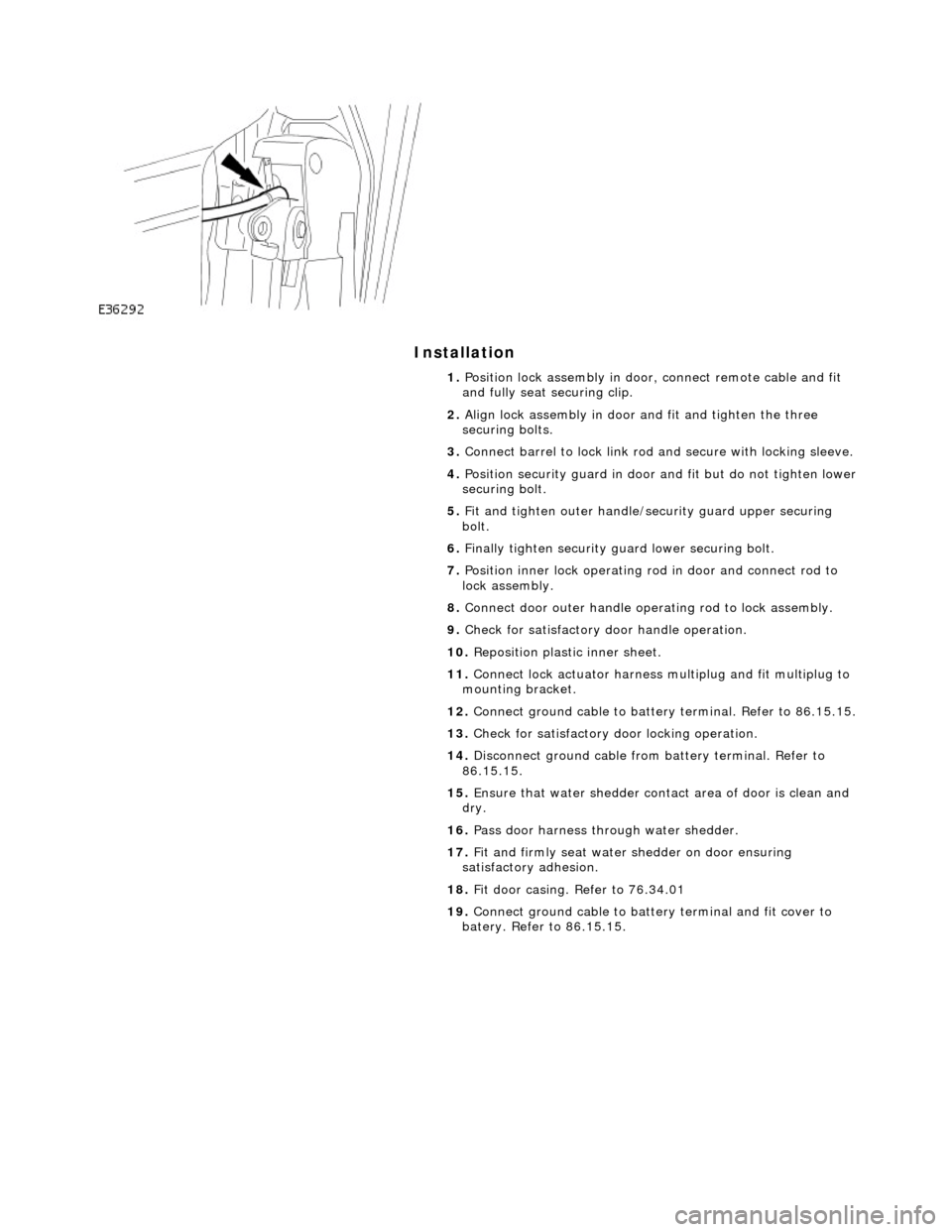
Installation
1. Position lock assembly in door, connect remote cable and fit
and fully seat securing clip.
2. Align lock assembly in door and fit and tighten the three
securing bolts.
3. Connect barrel to lock link rod and secure with locking sleeve.
4. Position security guard in door and fit but do not tighten lower
securing bolt.
5. Fit and tighten outer handle/security guard upper securing
bolt.
6. Finally tighten security guard lower securing bolt.
7. Position inner lock operating ro d in door and connect rod to
lock assembly.
8. Connect door outer handle operating rod to lock assembly.
9. Check for satisfactory door handle operation.
10. Reposition plastic inner sheet.
11. Connect lock actuator harness multiplug and fit multiplug to
mounting bracket.
12. Connect ground cable to battery terminal. Refer to 86.15.15.
13. Check for satisfactory door locking operation.
14. Disconnect ground cable from battery terminal. Refer to
86.15.15.
15. Ensure that water shedder contact area of door is clean and
dry.
16. Pass door harness through water shedder.
17. Fit and firmly seat water shedder on door ensuring
satisfactory adhesion.
18. Fit door casing. Refer to 76.34.01
19. Connect ground cable to battery terminal and fit cover to
batery. Refer to 86.15.15.
Page 2306 of 2490
Wipers and Washers - Wipers and Washers
Description and Operation
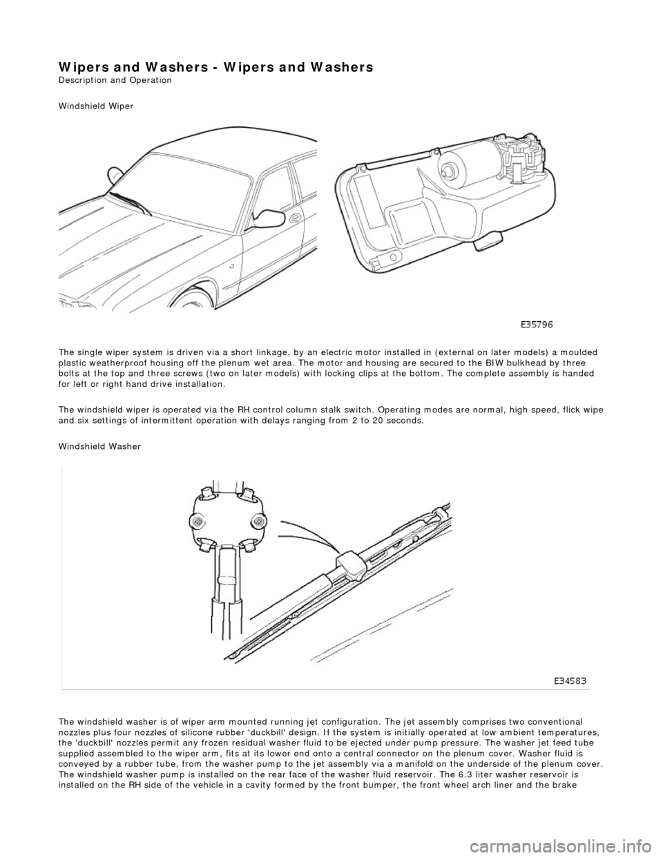
Windshield Wiper
The single wiper system is driven via a sh ort linkage, by an electric motor installed in (external on later models) a moulded
plastic weatherproof housing o ff the plenum wet area. The motor and housing are secured to the BIW bulkhead by three
bolts at the top and three screws (two on later models) with locking clips at the bottom. The complete assembly is handed
for left or right hand drive installation.
The windshield wiper is operated via the RH control column stalk switch. Operating modes are normal, high speed, flick wipe
and six settings of intermittent operation with delays ranging from 2 to 20 seconds.
Windshield Washer
The windshield washer is of wiper arm mounted running jet configuration. The je t assembly comprises two conventional
nozzles plus four nozzles of silicone rubbe r 'duckbill' design. If the system is initially operated at low ambient temperatures ,
the 'duckbill' nozzles permit an y frozen residual washer fluid to be ejected un der pump pressure. The washer jet feed tube
supplied assembled to the wiper ar m, fits at its lower end onto a central connector on the pl enum cover. Washer fluid is
conveyed by a rubber tube, from the washer pump to the jet assembly via a manifold on the underside of the plenum cover.
The windshield washer pump is installed on the rear face of the washer fluid reservoir. The 6.3 liter washer reservoir is
installed on the RH side of th e vehicle in a cavity formed by the front bu mper, the front wheel arch liner and the brake