Front seat JAGUAR X308 1998 2.G Service Manual
[x] Cancel search | Manufacturer: JAGUAR, Model Year: 1998, Model line: X308, Model: JAGUAR X308 1998 2.GPages: 2490, PDF Size: 69.81 MB
Page 2031 of 2490
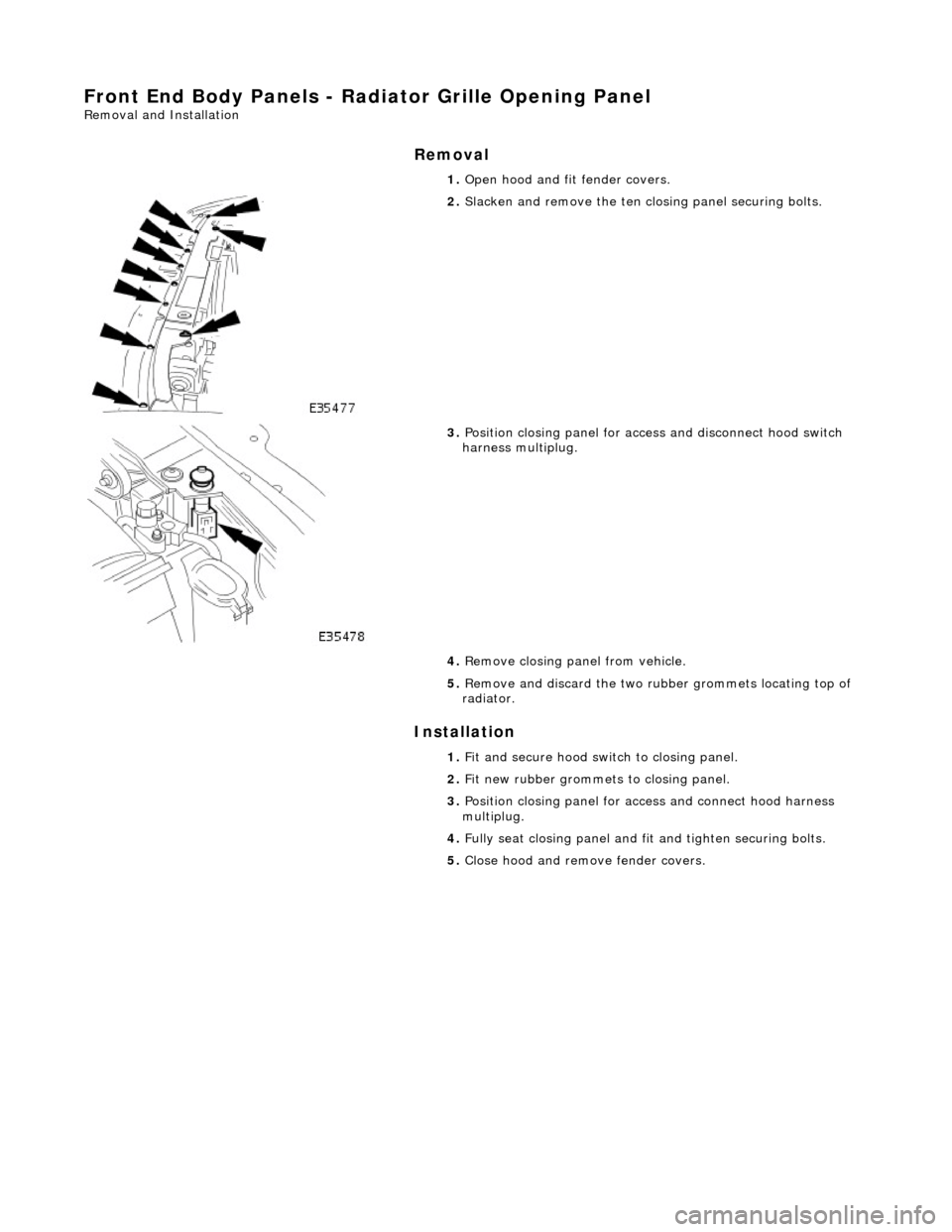
Front End Body Panels - Radiator Grille Opening Panel
Removal and Installation
Removal
Installation
1.
Open hood and fit fender covers.
2. Slacken and remove the ten cl osing panel securing bolts.
3. Position closing panel for access and disconnect hood switch
harness multiplug.
4. Remove closing panel from vehicle.
5. Remove and discard the two rubbe r grommets locating top of
radiator.
1. Fit and secure hood switch to closing panel.
2. Fit new rubber grommets to closing panel.
3. Position closing panel for access and connect hood harness
multiplug.
4. Fully seat closing panel and fit and tighten securing bolts.
5. Close hood and remove fender covers.
Page 2032 of 2490
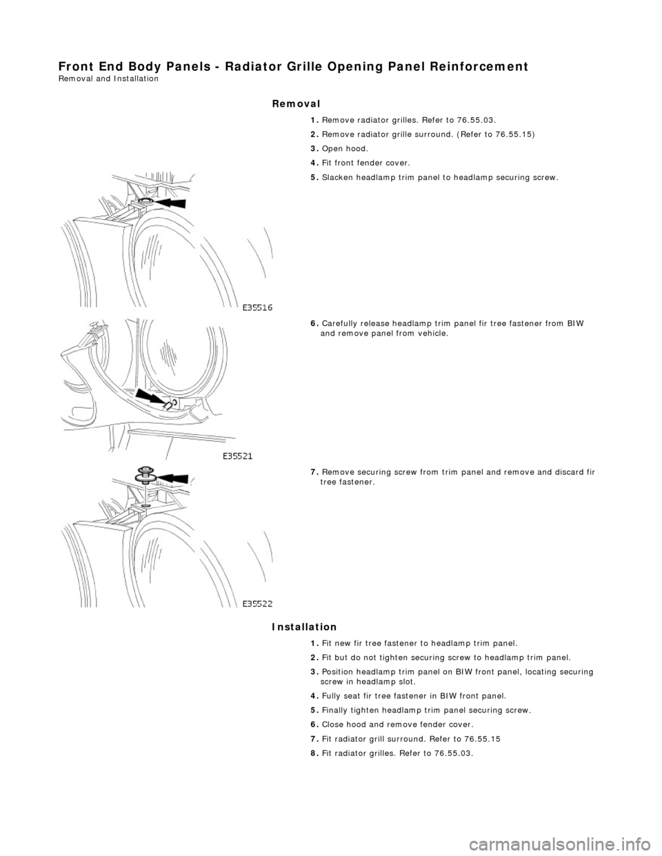
Front End Body Panels - Radiator Grille Opening Panel Reinforcement Removal and Installation
Removal
Installation
1.
Remove radiator grilles. Refer to 76.55.03.
2. Remove radiator grille surround. (Refer to 76.55.15)
3. Open hood.
4. Fit front fender cover.
5. Slacken headlamp trim panel to headlamp securing screw.
6. Carefully release headlamp trim panel fir tree fastener from BIW
and remove panel from vehicle.
7. Remove securing screw from trim panel and remove and discard fir
tree fastener.
1. Fit new fir tree fastener to headlamp trim panel.
2. Fit but do not tighten securing screw to headlamp trim panel.
3. Position headlamp trim panel on BIW front panel, locating securing
screw in headlamp slot.
4. Fully seat fir tree fastener in BIW front panel.
5. Finally tighten headlamp trim panel securing screw.
6. Close hood and remove fender cover.
7. Fit radiator grill surround. Refer to 76.55.15
8. Fit radiator grilles. Refer to 76.55.03.
Page 2039 of 2490
2.
Ensure that multiplugs are clea r of door front edge, and check
arm is fully retracted, then with assistance, lift door into
position and locate hinge pins.
3. Fit and fully tighten new hinge locking screws.
4. Position check arm bracket on 'A' post and fit and tighten
securing screws.
5. Fully open door and apply a thin co at of grease to both sides of
check arm.
6. Connect door harness multiplugs and fit and fully seat harness
gaiter in 'A' post.
7. Remove masking tape from front edge of door.
8. Check that door shuts correctly.
9. Wipe any excess grease from check arm.
10. Connect ground cable to batt ery terminal and fit battery
cover. Refer to 86.15.15.
Page 2040 of 2490
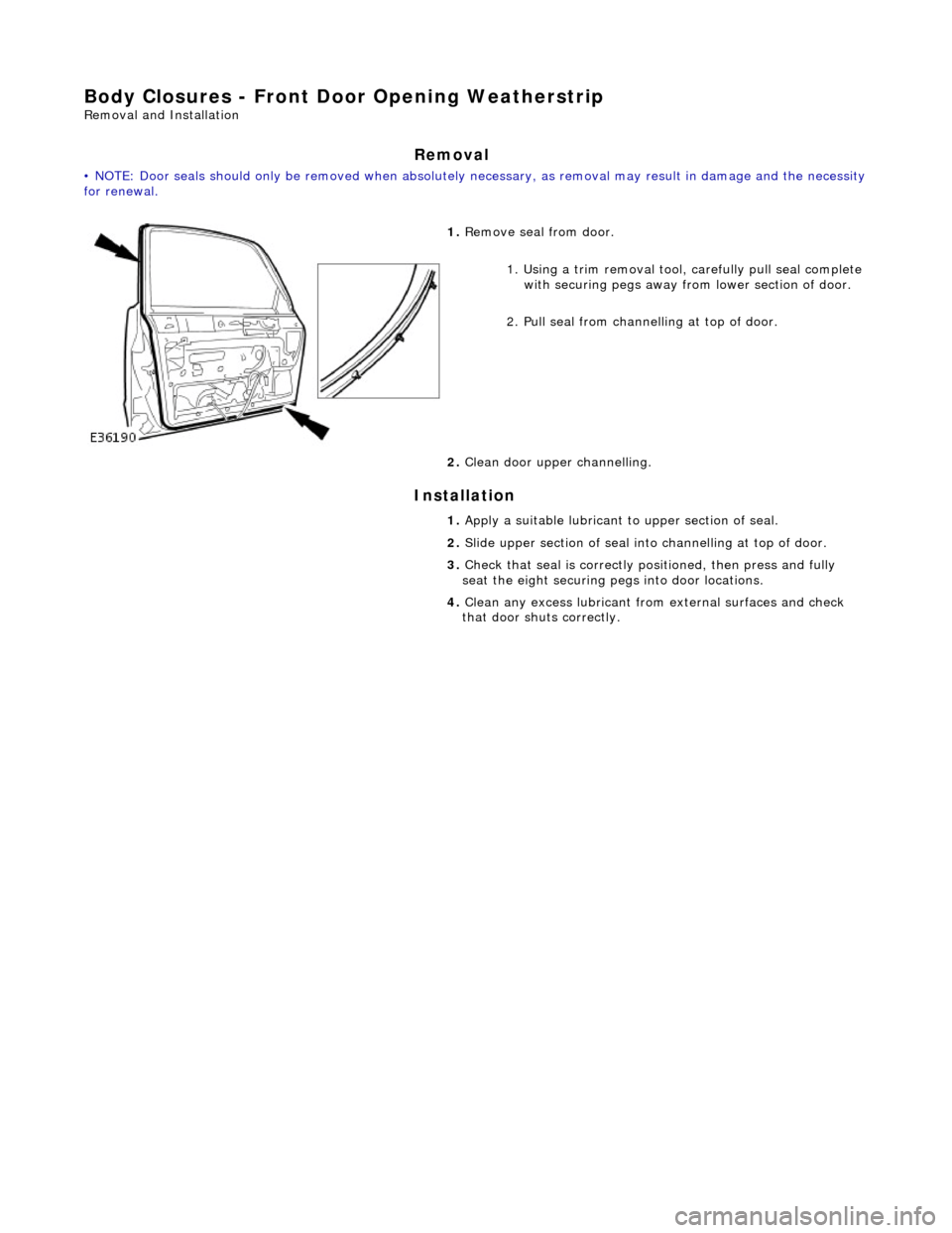
Body Closures - Front Door Opening Weatherstrip
Removal and Installation
Removal
• NOTE: Door seals should only be remove d when absolutely necessary, as removal may result in damage and the necessity for renewal.
Installation
1. Remove seal from door.
1. Using a trim removal tool, carefully pull seal complete
with securing pegs away from lower section of door.
2. Pull seal from chan nelling at top of door.
2. Clean door uppe r channelling.
1. Apply a suitable lubricant to upper section of seal.
2. Slide upper section of seal into channelling at top of door.
3. Check that seal is correctly positioned, then press and fully
seat the eight securing pegs into door locations.
4. Clean any excess lubricant from external surfaces and check
that door shuts correctly.
Page 2043 of 2490
Installation
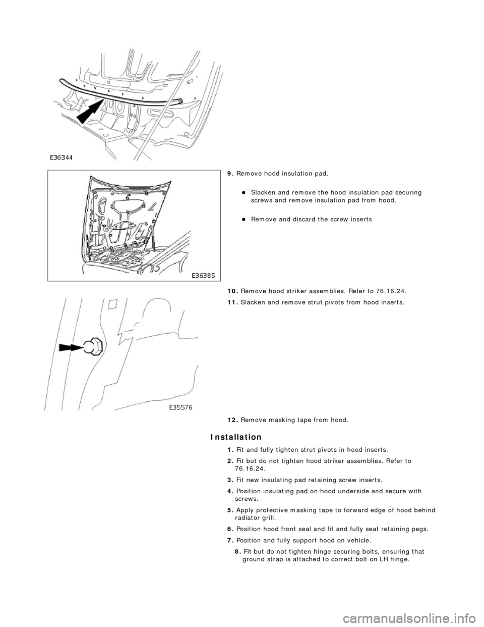
9. Remove hood insulation pad.
Slacken and remove the hood insulation pad securing
screws and remove insulation pad from hood.
Remove and discard the screw inserts
10. Remove hood striker assemb lies. Refer to 76.16.24.
11. Slacken and remove strut pivots from hood inserts.
12. Remove masking tape from hood.
1. Fit and fully tighten strut pivots in hood inserts.
2. Fit but do not tighten hood striker assemblies. Refer to
76.16.24.
3. Fit new insulating pad retaining screw inserts.
4. Position insulating pad on h ood underside and secure with
screws.
5. Apply protective masking tape to forward edge of hood behind
radiator grill.
6. Position hood front seal and fi t and fully seat retaining pegs.
7. Position and fully suppo rt hood on vehicle.
8. Fit but do not tighten hinge se curing bolts, ensuring that
ground strap is attached to correct bolt on LH hinge.
Page 2050 of 2490

Body Closures - Luggage Compartment Lid Opening Weatherstrip
Removal and Installation
Removal
Installation
1.
Remove trunk rear finisher. Refer to 76.19.44.
2. Commencing at front of trunk aperture, withdraw seal from
flange, exercising care on re aching bonded joint at latch
striker.
3. Clean trunk flange.
1. Commencing with bonded joint at latch striker, press seal onto
trunk flange.
2. Applying light tension, progress around trunk aperture firmly
seating seal onto flange.
3. Check that seal is free from kinks and trunk lid closes correctly.
4. Fit trunk rear finish er. Refer to 76.19.44.
Page 2052 of 2490

Body Closures - Luggage Compartment Lid Strut
Removal and Installation
Removal
Installation
1.
Remove trunk front liner. Refer to 76.19.31.
2. Place a suitable support under trunk lid.
3. Release strut from pivots.
1. Using a screwdriver, rele ase clip at rear end of
strut, withdraw end from trunk lid pivot and lower
strut for access.
2. Using a long screwdriver, release clip at front end of strut, withdraw end fro m pivot and remove strut
from vehicle.
1. Extend strut and fit front end onto pivot ensuring that retaining
clip fully seats.
2. Fit rear end of strut onto lid pi vot ensuring that retaining clip
fully seats.
3. Remove lid support and check that lid closes correctly.
4. Fit trunk front liner. Refer to 76.19.31.
Page 2054 of 2490
Interior Trim and Ornamentation - Interior Trim
Description and Operation
Carpets
The passenger compartment carpet is a one piece moulded constr uction with integral sound deadening material, heel mats
and driver's footrest. The carpet is attach ed to the vehicle floor by plastic clips fitted below the door treadplates. Removal of the carpet necessitates re moval of the front seats, lifting of the centre console rear extens ion and removal of the heelboard
carpet.
Fascia
The full width, slush moulded, soft feel PVC fascia is mounted on an injection moulded armature and is faced with wood
veneer. In addition to the air conditioning and central, outer and demisting vents, it accepts instrument packs dedicated to
market requirements and a centrally mounted analogue clock.
Doors
The one-piece door casings are trimmed in UEV to match the seating, with wood veneer at the waistline and a carpet insert
at the front lower corner. Each casing is secured to the door inner panel by fir tree press fast eners along the lower section,
two armrest fixings at the centre and vene er panel dowels and fixings at the top. The armrests which are common to front
and rear doors, are trimmed in matching leather or UEV according to specification. The door switchpacks, dedicated to
driver and front or rear passenger, are in corporated in the armrests. A speaker is in stalled in the lower section of each door
and a tweeter is incorporated behind each interior door handle escutcheon. Where premium ICE is fitted, the front tweeters
are installed in the upper A posts.
A, B, C and D Posts
On each side,a grained UEV finisher trimmed to match the headlining is secured to the 'A' post and cantrail by fir tree
fasteners locating in BIW apertures. The upper 'D' post finisher is trimmed and secured in the same manner. The single
piece'B/C' post finishers, also finished in grained matching UEV, each have a front se at belt exit aperture and are secured to
the BIW by four spring clips and two fir tree fasteners.
Headlining
The one-piece headlining consists of a 6mm thick polyurethane foam membrane covered with suede effect knitted polyester. The headlining is secured to the BIW roof by body tangs, the roof console, sun visors, combined grab handles and coat
hooks, the cantrail finishers and where fitt ed, the sliding roof finisher and clips.
Trunk
Carpet covered trims line the trunk and are secured by fir tr ee fasteners to the sides and front inner panel. The carpet
covered, two-section, removable trunk fl oor provides access to the spare wheel and wheel changing equipment, the battery
and electrical carrier. The floor board rests on the spare wheel, with the front and rear edges locating in blocks on the fuel
tank backboard and the rear of the body. The support blocks provide for two floor he ight settings to accommodate either a
space saver or full size spare wheel.A moulded finisher covering the rear of the trunk below the sill is secured to the rear
panel by tabs and fir tree fasteners. Finish er panels fitted to the rear lamp units provide trunk interior access to the lamps.
The trunk lid underside is fitted with a removabl e moulded liner and two trunk illumination lights.
Page 2056 of 2490

Interior Trim and Ornamentation - B-Pillar Trim Panel
Removal and Installation
Removal
1. Position front seat and squab fully forward.
2. Remove front seat belt upper and lower anchorages. Refer to
76.73.10.
3. Remove escutcheon from trim pad aperture and seat belt.
4. Remove draught welts from adjace nt door aperture flanges.
5. Using a trim removal tool and exercising care to avoid
damage, remove and discard th e two fir tree fasteners from
bottom of trim.
6. Carefully ease centre of trim pad inwards to release four
spring clips.
Page 2063 of 2490

Interior Trim and Ornamentation - Floor Covering
Removal and Installation
Removal
1. Remove battery cover and disc onnect ground cable from
battery terminal. Refer to 86.15.19.
2. Remove rear seat cushion. Refer to 76.70.37.
3. Remove front seats. Refer to 76.70.01
4. Remove 'J' gate surroun d. Refer to 76.25.24.
5. Remove centre console finish er veneer panel. Refer to
76.47.26.
6. Remove fascia centre veneer panel. Refer to 76.47.06.
7. Remove centre console assembly. Refer to 76.25.01.
8. Remove 'A' post lower trim pads. Refer to 76.13.30.
9. Remove 'B' post trim pads. Refer to operations in this section.
10. Slacken and remove centre console heater ducting securing
screw and remove ducting from vehicle..
11. Rotate heelboard fasteners 1/4 turn and remove both
heelboards from vehicle.
12. Remove front sill treadplates. Refer to operations in this
section.
13. Remove rear sill treadplates. Refer to operations in this
section.
14. Release the carpet retainers fro m BIW flanges at each side.
15. Release the two carpet rear retainers from BIW brackets.