Front seat JAGUAR X308 1998 2.G Owner's Manual
[x] Cancel search | Manufacturer: JAGUAR, Model Year: 1998, Model line: X308, Model: JAGUAR X308 1998 2.GPages: 2490, PDF Size: 69.81 MB
Page 1513 of 2490

Automatic Transmission/Transaxle External Contro ls - 4.0L SC V8 - AJ26 -
Selector Lever Cable and Bracket
Removal and Installation
Removal
1. Disconnect the vehicle battery ground lead.
2. Position the selector to N.
3. Remove the J-gate surround, Section 501-05.
4. Remove the console finisher ve neer panel, Section 501-12.
5. Remove the center console assembly, Section 501-12.
6. Raise the vehicle for access.
7. Detach the gear selector cable from the transmission unit.
1. Remove the nut which secures the selector cable ball pin to the selector lever.
2. Lower the transmissi on lift for access.
3. Remove the bolts which secure the selector cable to the transmission casing.
8. Reposition the selector cable.
9. Remove the LH front seat, Section 501-10.
10. Reposition the LH floo r carpet for access.
11. Remove the selector cable to tunnel clip tie strap.
12. Detach the selector cable from the gear shift assembly.
1. Remove the inner cable to shift lever nut.
Page 1516 of 2490

Automatic Transmission/Transaxle External Contro ls - 4.0L SC V8 - AJ26 -
Selector Lever Gate Finish Panel
Removal and Installation
Removal
Installation
1.
Apply protective tape to veneer along each side of 'J' gate
finisher.
2. Using a screwdriver in the slot in front of the finisher,
carefully lift the finisher an d ease it from the 'J' gate
surround.
1. Position finisher over gear selector.
2. Firmly seat finisher on veneer panel.
3. Remove protective tape from ve neer panel and using a suitable
cleaner, remove any residual adhesive.
Page 1925 of 2490

Exterior Lighting - Fog Lamp Switch
Removal and Installation
Removal
Installation
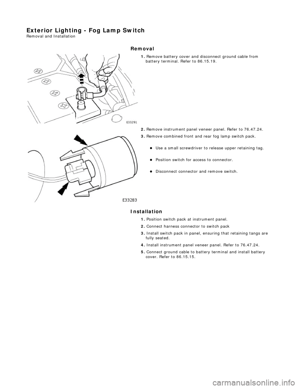
1. Remove battery cover and disc onnect ground cable from
battery terminal. Refer to 86.15.19.
2. Remove instrument pa nel veneer panel. Refer to 76.47.24.
3. Remove combined front and rear fog lamp switch pack.
Use a small screwdriver to re lease upper retaining tag.
Position switch for access to connector.
Disconnect connector and remove switch.
1. Position switch pack at instrument panel.
2. Connect harness connector to switch pack
3. Install switch pack in panel, ensuring that retaining tangs are
fully seated.
4. Install instrument panel veneer panel. Refer to 76.47.24.
5. Connect ground cable to batter y terminal and install battery
cover. Refer to 86.15.15.
Page 1927 of 2490

Exterior Lighting - Front Fog Lamp Bulb
Removal and Installation
Removal
Installation
1.
Remove undertray for ac cess. Refer to 76.22.90.
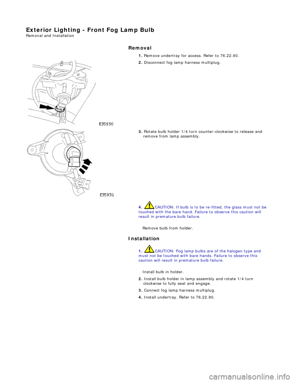
2. Disconnect fog lamp harness multiplug.
3. Rotate bulb holder 1/4 turn counter-clockwise to release and
remove from lamp assembly.
4. CAUTION: If bulb is to be re -fitted, the glass must not be
touched with the bare hand. Failure to observe this caution will
result in premature bulb failure.
Remove bulb from holder.
1. CAUTION: Fog lamp bulbs are of the halogen type and
must not be touched with bare hands. Failure to observe this
caution will result in premature bulb failure.
Install bulb in holder.
2. Install bulb holder in lamp assembly and rotate 1/4 turn
clockwise to fully seat and engage.
3. Connect fog lamp harness multiplug.
4. Install undertray. Refer to 76.22.90.
Page 1928 of 2490

Exterior Lighting - Front Side Marker Lamp
Removal and Installation
Removal
Installation
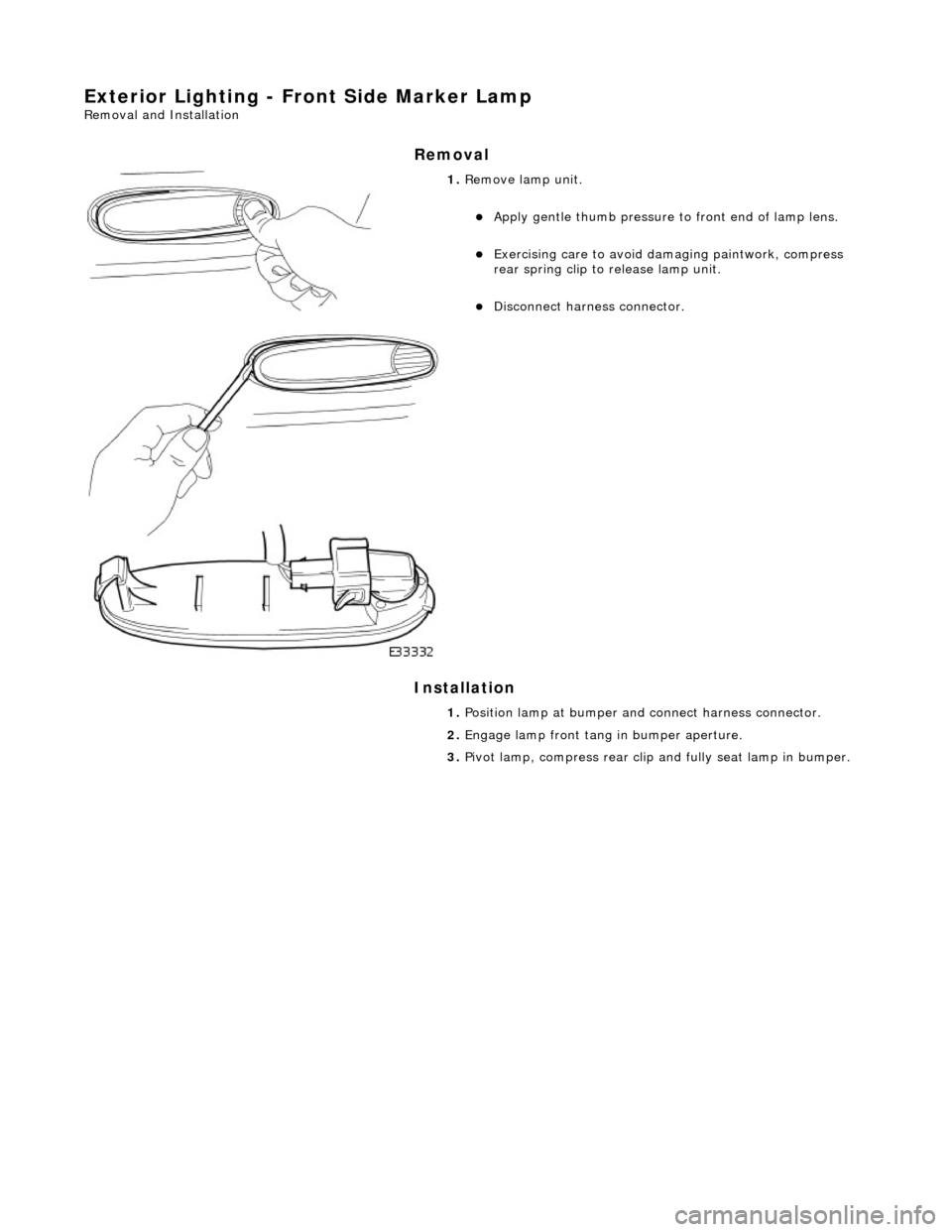
1. Remove lamp unit.
Apply gentle thumb pressure to front end of lamp lens.
Exercising care to avoid damaging paintwork, compress
rear spring clip to release lamp unit.
Disconnect harness connector.
1. Position lamp at bumper an d connect harness connector.
2. Engage lamp front tang in bumper aperture.
3. Pivot lamp, compress rear clip and fully seat lamp in bumper.
Page 1930 of 2490

Installation
1. Install bulb in holder.
2. Install bulb and bulb holder in lamp assembly and rotate 1/4
turn clockwise to seat and retain.
3. Position direction lamp at bumper aperture and connect
harness multiplug.
4. Engage front end tang of lamp in bumper aperture.
5. Pivot lamp assembly and firmly seat rear retaining clip in
bumper aperture.
Page 1954 of 2490

Exterior Lighting - Rear Side Marker Lamp
Removal and Installation
Removal
Installation
1. Applying firm thumb pressure to front of lens, pivot lamp
assembly for access to rear end.
2. Exercising care to avoid dama ging paintwork, use a small
screwdriver to press and re lease rear retaining clip.
3. Withdraw lamp from bumper for access and disconnect harness connector.
1. Position lamp at bumper ap erture and connect harness
connector.
2. Engage front end tang of lamp in bumper aperture.
3. Pivot lamp assembly and firmly seat rear retaining clip in
bumper aperture.
Page 1956 of 2490

Installation
1. Install bulb in holder.
2. Install bulb and bulb holder in lamp assembly and rotate 1/4
turn clockwise to seat and retain.
3. Position lamp at bumper ap erture and connect harness
connector.
4. Engage front end tang in bumper aperture.
5. Pivot lamp assembly and firmly seat rear retaining clip in
bumper aperture.
Page 1958 of 2490

Exterior Lighting - Side Lamp/Front Turn Signal Lamp
Removal and Installation
Removal
Installation
1. Applying firm hand pressure to inner end, pivot indicator lamp
assembly for access to outer end.
2. Exercising care to avoid dama ging paintwork, use a small
screwdriver at outer end of lamp, to press and release retaining clip.
3. Withdraw lamp from bumper for access and disconnect harness multiplug.
1. Position direction indicator la mp at bumper aperture and
connect harness multiplug.
2. Engage inner end tang of lamp in bumper aperture.
3. Pivot lamp assembly and firmly seat outer retaining clip in
bumper aperture.
Page 1973 of 2490

Module Communications Network - Communications Network
Description and Operation
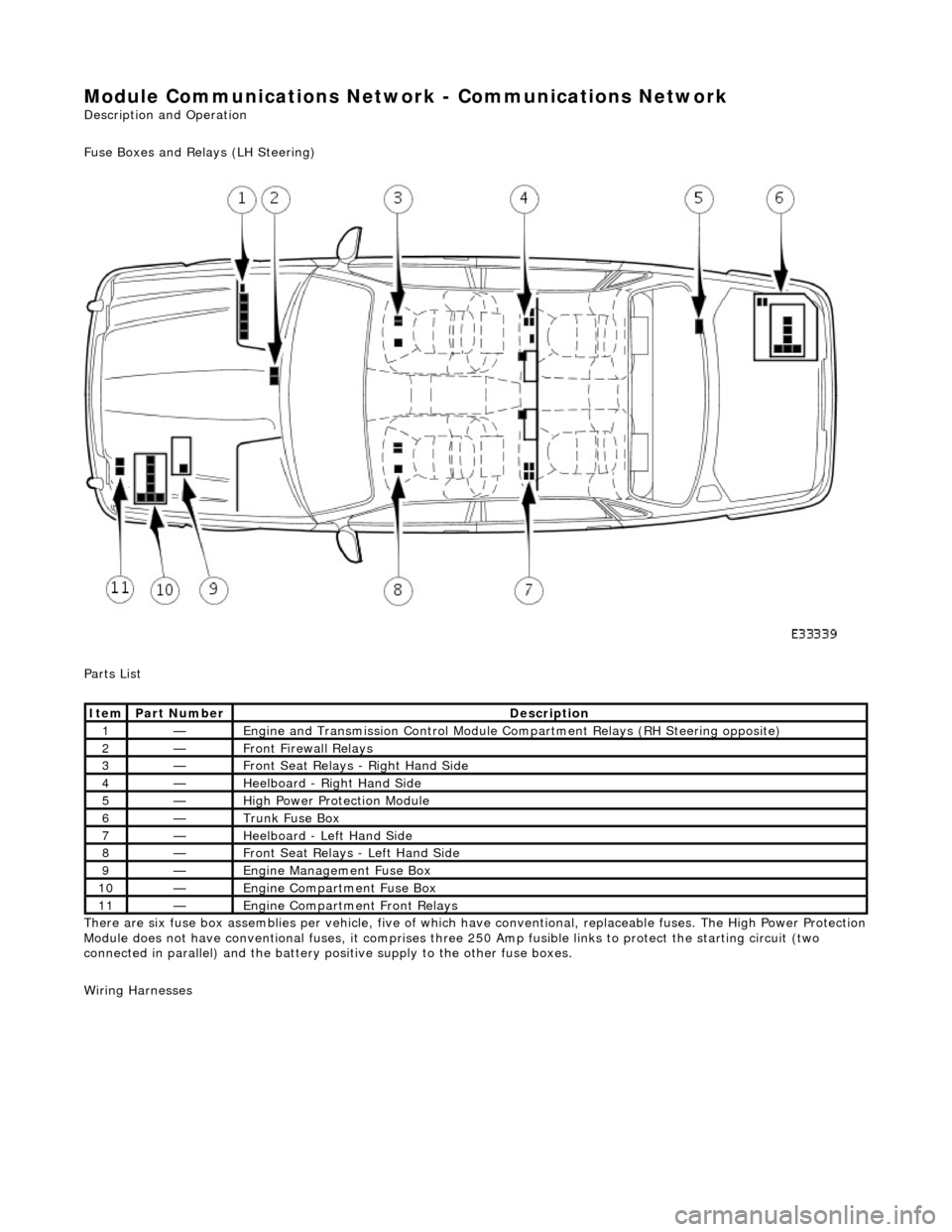
Fuse Boxes and Relays (LH Steering)
Parts List
There are six fuse box assemblies per vehicle, five of which have conventional, replaceable fuses. The High Power Protection
Module does not have conventional fuses, it comprises three 250 Amp fusible links to protect the starting circuit (two
connected in parallel) and the battery positive supply to the other fuse boxes.
Wiring Harnesses
ItemPart NumberDescription
1—Engine and Transmission Cont rol Module Compartment Relays (RH Steering opposite)
2—Front Firewall Relays
3—Front Seat Relays - Right Hand Side
4—Heelboard - Right Hand Side
5—High Power Protection Module
6—Trunk Fuse Box
7—Heelboard - Left Hand Side
8—Front Seat Relays - Left Hand Side
9—Engine Management Fuse Box
10—Engine Compartment Fuse Box
11—Engine Compartment Front Relays