fuel injector JAGUAR X308 1998 2.G Service Manual
[x] Cancel search | Manufacturer: JAGUAR, Model Year: 1998, Model line: X308, Model: JAGUAR X308 1998 2.GPages: 2490, PDF Size: 69.81 MB
Page 1078 of 2490
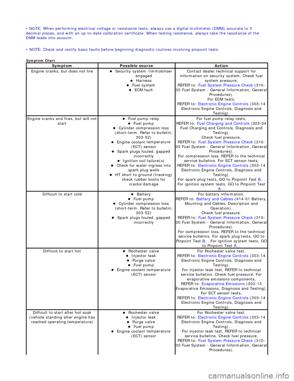
• NO
TE: When performing electrical voltag
e or resistance tests, always use a digital multimeter (DMM) accurate to 3
decimal places, and with an up-t o-date calibration certificate. When testing resistance, always take the resistance of the
DMM leads into account.
• NOTE: Check and rectify basic faults before beginning diagnostic ro utines involving pinpoint tests.
Sym
ptom Chart
Sy
m
ptom
Possib
l
e source
Acti
o
n
Engine
cranks, but does
not fire
Secu
rit
y system /Immobiliser
engaged
Harness Fue l
system
ECM fault
Contact deal er techni
cal support for
information on security system. Check fuel
system pressure,
REFER to: Fuel System Pressure Check
(310
-
00 Fuel System - Genera l Information, General
Procedures).
For ECM tests,
REFER to: Electronic Engine Controls
(303
-14
Electronic Engine Co ntrols, Diagnosis and
Testing).
Engine cranks and
fi
res, but will not
start
Fu
el pump relay
Fuel
pump
Cyl
i
nder compression loss
(short-term. Refer to bulletin; 303-52)
Engine coolan t
temperature
(ECT) sensor
Spark plugs fouled, gapp
ed
incorrectly
Ignition coil fail
ure(s)
Check f
o
r water ingress into
spark plug wells
HT sho rt to ground (tracking)
check rubber
boots for
cracks/damage
Fo
r fuel pump relay tests,
REFER to: Fuel Charging and Controls
(303
-04
Fuel Charging and Controls, Diagnosis and Testing).
Check fuel pressure,
REFER to: Fuel System Pressure Check
(310
-
00 Fuel System - Genera l Information, General
Procedures).
For compression loss, REFER to the technical service bulletins. For ECT sensor tests,
REFER to: Electronic Engine Controls
(303
-14
Electronic Engine Co ntrols, Diagnosis and
Testing).
For spark plug tests, GO to Pinpoint Test B.
.
For ign i
tion system tests, GO to Pinpoint Test
A.
.
Diff
icult to start cold
Batt
ery Fuel
pump
Cyl
i
nder compression loss
(short-term. Refer to bulletin; 303-52)
Spark plugs fouled, gapp
ed
incorrectly
F o
r battery information,
REFER to: Battery and Cables
(414
-01 Battery,
Mounting and Cables, Description and Operation).
Check fuel pressure.
REFER to: Fuel System Pressure Check
(310
-
00 Fuel System - Genera l Information, General
Procedures).
For compression loss, REFER to the technical service bulletins. For spark plug tests, GO to
Pinpoint Test B.
. For ig
nition system tests, GO
to Pinpoint Test A.
.
Diff
icult to start hot
Roc
h
ester valve
Injec
t
or leak
Purge
val
ve
Fue
l
pump
Engine coolan
t
temperature
(ECT) sensor
F or R
ochester
valve test,
REFER to: Electronic Engine Controls
(303
-14
Electronic Engine Co ntrols, Diagnosis and
Testing).
For injector leak test, REFER to technical
service bulletins. Check fuel pressure. For evaporative emissions components,
REFER to: Evaporative Emissions
(303
-13
Evaporative Emissions, Diagnosis and Testing).
For ECT sensor tests,
REFER to: Electronic Engine Controls
(303
-14
Electronic Engine Co ntrols, Diagnosis and
Testing).
D iff
icult to start after hot soak
(vehicle standing after engine has reached operating temperature)
Roc h
ester valve
Injec
t
or leak
Purge
val
ve
Fue
l
pump
Engine coolan
t
temperature
(ECT) sensor
F or R
ochester
valve test,
REFER to: Electronic Engine Controls
(303
-14
Electronic Engine Co ntrols, Diagnosis and
Testing).
For injector leak test, REFER to technical service bulletins. Check fuel pressure,
REFER to: Fuel System Pressure Check
(310
-
00 Fuel System - Genera l Information, General
Procedures).
Page 1083 of 2490
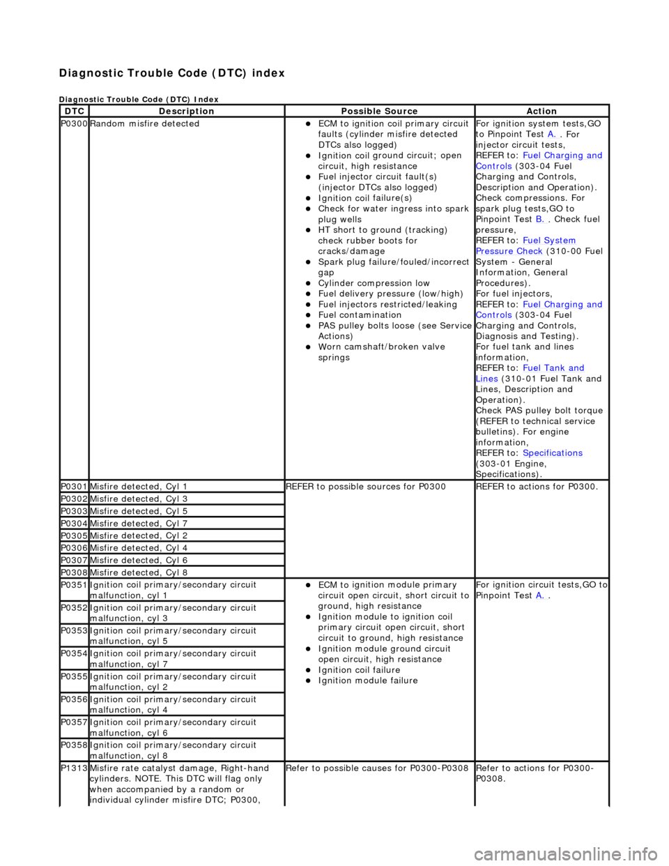
Diagnostic Trouble Code (D
TC) index
D
iagnostic Trouble Code (DTC) Index
DT
C
De
scription
Possib
le Source
Acti
on
P0300Ran
dom misfire detected
ECM t
o ignition coil primary circuit
faults (cylinder misfire detected
DTCs also logged)
Ignition coil
ground circuit; open
circuit, high resistance
F
uel injector circuit fault(s)
(injector DTCs also logged)
Ignition coil
failure(s)
Check f
or water ingress into spark
plug wells
HT sho
rt to ground (tracking)
check rubber boots for
cracks/damage
Spark plug
failure/fouled/incorrect
gap
Cy
linder compression low
F
uel delivery pressure (low/high)
F
uel injectors restricted/leaking
Fuel contamination
P
AS pulley bolts loose (see Service
Actions)
W
orn camshaft/broken valve
springs
For ign
ition system tests,GO
to Pinpoint Test A.
. For
inje
ctor circuit tests,
REFER to: Fuel Charging and
Controls (30
3-04 Fuel
Charging and Controls,
Description and Operation).
Check compressions. For
spark plug tests,GO to
Pinpoint Test B.
.
Check fuel
pressure,
REFER to: Fuel System
Pressure Check (31
0-00 Fuel
System - General
Information, General
Procedures).
For fuel injectors,
REFER to: Fuel Charging and
Controls (30
3-04 Fuel
Charging and Controls,
Diagnosis and Testing).
For fuel tank and lines
information,
REFER to: Fuel Tank and
Lin
es
(310-01 Fuel Tank and
Lines, Description and
Operation).
Check PAS pulley bolt torque
(REFER to technical service
bulletins). For engine
information,
REFER to: Specifications
(3
03-01 Engine,
Specifications).
P0301Misfire
detected, Cyl 1
R
EFER to possible sources for P0300
R
EFER to actions for P0300.
P0302Misfire
detected, Cyl 3
P0303Misfire
detected, Cyl 5
P0304Misfire
detected, Cyl 7
P0305Misfire
detected, Cyl 2
P0306Misfire
detected, Cyl 4
P0307Misfire
detected, Cyl 6
P0308Misfire
detected, Cyl 8
P0351Igni
tion coil primary/secondary circuit
malfunction, cyl 1
ECM to
ignition module primary
circuit open circuit, short circuit to
ground, high resistance
Igni
tion module to ignition coil
primary circuit open circuit, short
circuit to ground, high resistance
Ignition modu
le ground circuit
open circuit, hi gh resistance
Ignition coil
failure
Ignition modul
e failure
F
or ignition circuit tests,GO to
Pinpoint Test A.
.
P0352Igni
tion coil primary/secondary circuit
malfunction, cyl 3
P0353Igni
tion coil primary/secondary circuit
malfunction, cyl 5
P0354Igni
tion coil primary/secondary circuit
malfunction, cyl 7
P0355Igni
tion coil primary/secondary circuit
malfunction, cyl 2
P0356Igni
tion coil primary/secondary circuit
malfunction, cyl 4
P0357Igni
tion coil primary/secondary circuit
malfunction, cyl 6
P0358Igni
tion coil primary/secondary circuit
malfunction, cyl 8
P1313Misfire rate
catalyst damage, Right-hand
cylinders. NOTE. This DTC will flag only
when accompanied by a random or
individual cylinder misfire DTC; P0300,
R
efer to possible causes for P0300-P0308
R
efer to actions for P0300-
P0308.
Page 1138 of 2490
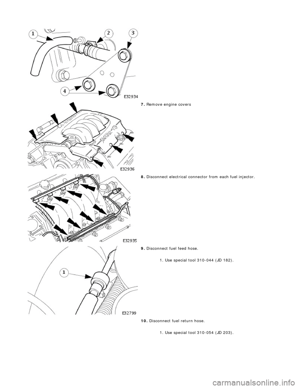
7. Re
move engine covers
8. Disc onne
ct electrical connector from each fuel injector.
9. Disc
onnect fuel feed hose.
1. Use special tool 310-044 (JD 182).
10. Disconnect fuel return hose.
1. Use special tool 310-054 (JD 203).
Page 1140 of 2490
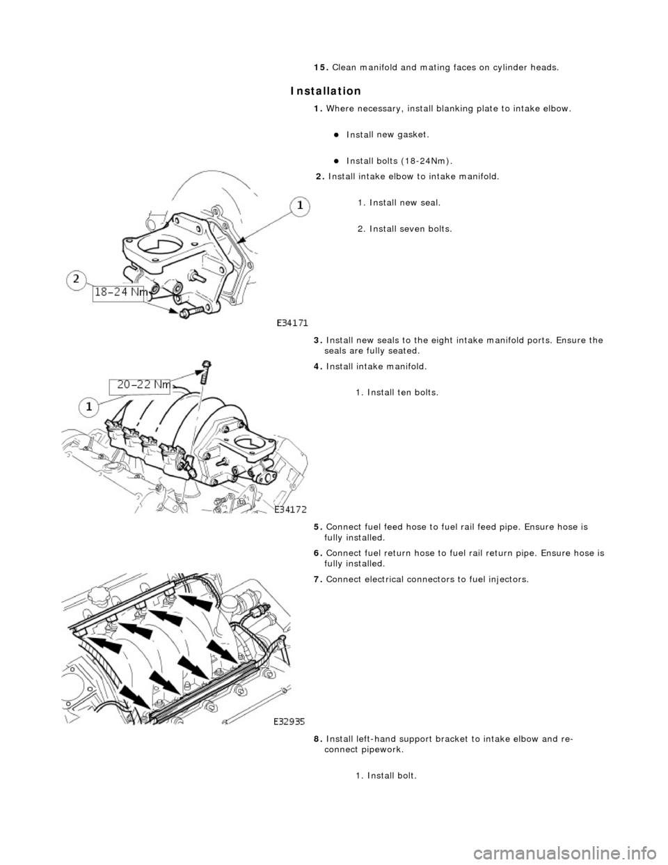
In
stallation
15.
Cle
an manifold and mating faces on cylinder heads.
1. Where necessary, install blanking plate to intake elbow.
Inst al
l new gasket.
Inst
al
l bolts (18-24Nm).
2. Inst al
l intake elbow to intake manifold.
1. Install new seal.
2. Install seven bolts.
3. Install new seals to the eight intake manifold ports. Ensure the
seals are fully seated.
4. Inst al
l intake manifold.
1. Install ten bolts.
5. Connect fuel feed hose to fuel rail feed pipe. Ensure hose is
fully installed.
6. Connect fuel return hose to fuel rail return pipe. Ensure hose is
fully installed.
7. Con n
ect electrical connectors to fuel injectors.
8. Install left-hand support brac ket to intake elbow and re-
connect pipework.
1. Install bolt.
Page 1149 of 2490
The E
VAP canister purge valve controls th
e flow rate of fuel vapour drawn into the engine during the canister purge
operation. The valve is opened by a vacu um feed from the induction elbow : the vacu um feed is controlled by the integral
valve solenoid and is applied when the so lenoid is energised. The solenoid is pulsed on (energised) and off by a fixed
frequency (100Hz) variable pulse width control signal (pulse width modulation). By varying the pulse on to off time, the
ECM controls the duty cycle of the valve (time that the valve is open to time closed) and thus the vapour flow rate to the
engine.
With no ECM signal applied to the va lve solenoid, the valve remains closed.
Can
ister Purge Operation
The
following pre-conditions are ne
cessary for purging to commence :
aft
er battery disconnection/reconnection, engine
management adaptations must be re-instated.
engine has run for
at least 8 seconds.
engi
ne coolant temperature is not less than 70 °C.
engine
not running in the fuel
cut off condition (eg overrun).
t
he adaptive fuel correction
function has not registered a rich or lean failure
t
he evaporative emission leak test has not failed
no faults have been diagnosted in th
e rel
evant sensor and valve circuits -
Air Flow Meter (AFM), Engine Coolant
Temperature sensor, Evaporativ e Canister Purge valve and Canister Close Valve (CCV).
If these conditions have been satisfied, purging is started. If any failures are registered, purging is inhibited.
The canister(s) is purged during each driv e cycle at various rates in accordance with the prevailing engine conditions. The
engine management software st ores a map of engine speed (RPM) against engine load (grams of air inducted / rev). For
any given engine speed and load, a vapour purge rate is assigned (purge rate increases with engine speed and load).
The preset purge rates are base d on the assumption of a vapour concentratio n of 100%. The actual amount of vapour is
measured by the closed loop fueling system : the input of evaporative fuel into the engine causes the outputs from the
upstream oxygen sensors to change, the am ount of change providing a measure of the vapour concentration. This feedback
causes the original purge rate to be adju sted and also reduces the amount of fuel input via the injectors to maintain the
correct air to fuel ratio.
Engine speed/load mapping and the corresp onding purge rates are different for single canister, running loss and ORVR
evaporative systems.
Page 1191 of 2490
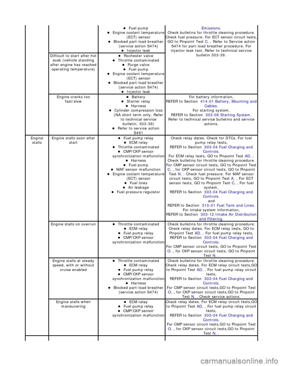
Fue
l pump
Engine coolan
t temperature
(ECT) sensor
Blocked part-load breather (
service action S474)
Injec
tor leak
Emiss
ions
.
Check bull
etins for throttle cleaning procedure.
Check fuel pressure. For ECT sensor circuit tests,
GO to Pinpoint Test C.
. Refer to Servi
ce action
S474 for part-load breather procedure. For
injector leak test, Refer to technical service bulletin 303-39.
D
ifficult to start after hot
soak (vehicle standing
after engine has reached operating temperature)
Roc
hester valve
Thr
ottle contaminated
Purge
valve
Fue
l pump
Engine coolan
t temperature
(ECT) sensor
Blocked part-load breather (
service action S474)
Injec
tor leak
Engine cranks too
fa
st/slow
Batt
ery
Starter relay Harness Cyl
inder compression loss
(NA short term only. Refer to technical service bulletin; 303-39)
R
efer to service action
S491
F
or battery information,
REFER to Section 414
-0
1 Battery, Mounting and
Cables.
F
or starting system.
REFER to Section 303
-06 Sta
rting System
.
R
efer to technical servic
e bulletins and service
actions.
Engine
stalls
Engine st
alls soon after
start
F
uel pump relay
ECM relay Thr
ottle contaminated
CMP/CKP sen
sor
synchronization malfunction
Harness Fue
l pump
MAF
sensor malfunction
Engine coolan
t temperature
(ECT) sensor
Fue
l lines
Air leakage
F
uel pressure regulator
Check r
elay dates. Chec
k for DTCs. For fuel
pump relay tests,
REFER to Section 303
-0
4 Fuel Charging and
Controls.
F
or ECM relay tests, GO to Pinpoint Test
AD.
.
Check bull
etins for throttle cleaning procedure.
For CMP sensor circuit test s, GO to Pinpoint Test
C.
, for
CKP sensor circuit tests, GO to Pinpoint
Test N.
. Check fuel
pressure. For MAF sensor
circuit tests, GO to Pinpoint Test A.
. For EC
T
sensor tests, GO to Pinpoint Test C.
. F
or fuel
system,
REFER to Section 303
-0
4 Fuel Charging and
Controls.
and
REF
ER to Section 310
-0
1 Fuel Tank and Lines
. F
or intake system information,
REFER to Section 303
-1
2 Intake Air Distribution
and F
iltering
.
Engine
stalls on overrun
Thr
ottle contaminated
ECM relay F
uel pump relay
CMP/CKP sen
sor
synchronization malfunction
Check bull
etins for throttle cleaning procedure.
Check relay dates. For ECM relay tests, GO to Pinpoint Test AD.
. F
or fuel pump relay tests,
REFER to Section 303
-0
4 Fuel Charging and
Controls.
F
or CMP sensor circuit test
s, GO to Pinpoint Test
O.
, for
CKP sensor circuit tests, GO to Pinpoint
Test N.
.
E
ngine stalls at steady
speed, with or without cruise enabled
Thr
ottle contaminated
ECM relay F
uel pump relay
CMP/CKP sen
sor
synchronization malfunction
Harness Blocked part-load breather
(
service action S474)
Check bull
etins for throttle cleaning procedure.
Check relay dates. For EC M relay circuit tests,GO
to Pinpoint Test AD.
. F
or fuel pump relay circuit
tests,
REFER to Section 303
-0
4 Fuel Charging and
Controls.
F
or CMP sensor circuit test
s,GO to Pinpoint Test
O.
, for
CKP sensor circuit tests,GO to Pinpoint
Test N.
. Che
ck service actions.
Engine st
alls when
maneuvering
ECM relay F
uel pump relay
CMP/CKP sen
sor
synchronization malfunction
Check r
elay dates. For EC
M relay circuit tests,GO
to Pinpoint Test AD.
. F
or fuel pump relay circuit
tests,
REFER to Section 303
-0
4 Fuel Charging and
Controls.
F
or CMP sensor circuit test
s,GO to Pinpoint Test
O.
, for
CKP sensor circuit tests,GO to Pinpoint
Test N.
.
Page 1196 of 2490
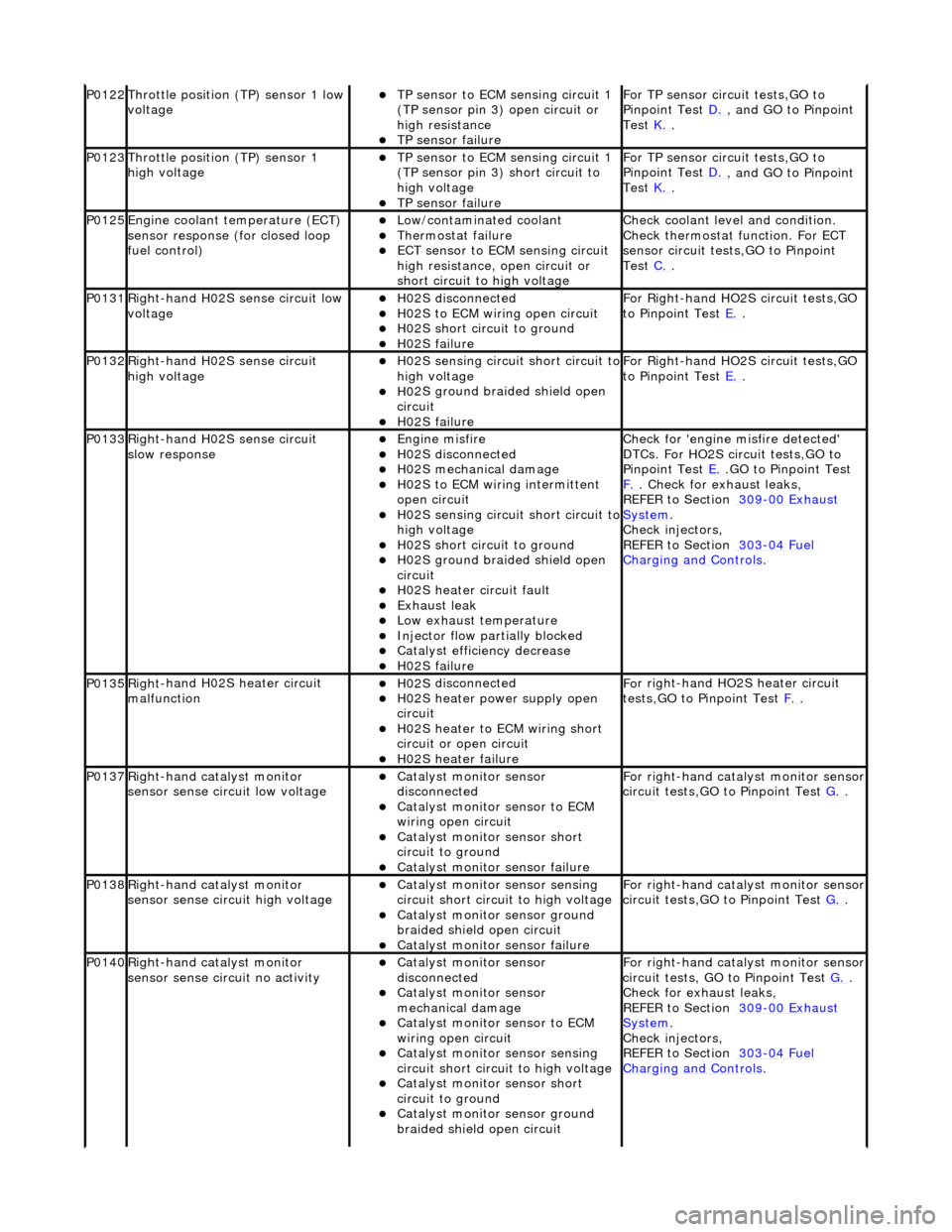
P0122Throttle
position (TP) sensor 1 low
voltage
TP se ns
or to ECM sensing circuit 1
(TP sensor pin 3) open circuit or
high resistance
TP sensor fail
ure
F
o
r TP sensor circ
uit tests,GO to
Pinpoint Test D.
, and GO
to Pinpoint
Test K.
.
P0123Throttl e
position (TP) sensor 1
high voltage
TP se ns
or to ECM sensing circuit 1
(TP sensor pin 3) short circuit to
high voltage
TP sensor fail
ure
F
o
r TP sensor circ
uit tests,GO to
Pinpoint Test D.
, and GO
to Pinpoint
Test K.
.
P0125En
gine coolant temperature (ECT)
sensor response (for closed loop
fuel control)
Low/contaminated coolant Therm o
stat failure
ECT se
ns
or to ECM sensing circuit
high resistance, open circuit or
short circuit to high voltage
Che c
k coolant level and condition.
Check thermostat function. For ECT
sensor circuit tests,GO to Pinpoint
Test C.
.
P0131Right -
hand H02S sense circuit low
voltage
H02 S
disconnected
H0
2S to
ECM wiring open circuit
H0
2S short ci
rcuit to ground
H0
2S fail
ure
F
or R
ight-hand HO2S circuit tests,GO
to Pinpoint Test E.
.
P0132Right-
hand H02S sense circuit
high voltage
H02 S
sensing circuit short circuit to
high voltage
H0 2S groun
d braided shield open
circuit
H0 2S fail
ure
F
or R
ight-hand HO2S circuit tests,GO
to Pinpoint Test E.
.
P0133Right-
hand H02S sense circuit
slow response
Engine m
isfire
H02
S
disconnected
H0
2S mechanical damage
H0
2S to
ECM wiring intermittent
open circuit
H02 S
sensing circuit short circuit to
high voltage
H02S short ci
rcuit to ground
H02S groun
d braided shield open
circuit
H0 2S heater circuit faul
t
Exhaus
t leak
Low e
x
haust temperature
Injector fl
ow parti
ally blocked
Catal
y
st efficiency decrease
H0
2S fail
ure
Chec
k for 'en
gine misfire detected'
DTCs. For HO2S circuit tests,GO to
Pinpoint Test E.
.G
O to Pinpoint Test
F.
. Check for exhaust leaks,
REF
ER to Section 309
-00
Ex
haust
Sy
ste
m
.
Chec k inje
ctors,
REFER to Section 303
-04 Fu
el
Charging and Cont
rols
.
P0135Right
-
hand H02S heater circuit
malfunction
H02 S
disconnected
H0
2S h
eater power supply open
circuit
H0 2S heater to ECM wi
ring short
circuit or open circuit
H0 2S heater fai
lure
F
o
r right-hand HO2S heater circuit
tests,GO to Pinpoint Test F.
.
P0137Right-
hand catalyst monitor
sensor sense circuit low voltage
Catal y
st monitor sensor
disconnected
Catal y
st monitor sensor to ECM
wiring open circuit
Catal y
st monitor sensor short
circuit to ground
Cat a
lyst monitor sensor failure
F
or ri
ght-hand catalyst monitor sensor
circuit tests,GO to Pinpoint Test G.
.
P0138Right -
hand catalyst monitor
sensor sense circuit high voltage
Catal y
st monitor sensor sensing
circuit short circuit to high voltage
Catalyst
monitor sensor ground
braided shield open circuit
Cata
lyst monitor sensor failure
F
or ri
ght-hand catalyst monitor sensor
circuit tests,GO to Pinpoint Test G.
.
P0140Right -
hand catalyst monitor
sensor sense circuit no activity
Catal y
st monitor sensor
disconnected
Catal y
st monitor sensor
mechanical damage
Catal y
st monitor sensor to ECM
wiring open circuit
Catal y
st monitor sensor sensing
circuit short circuit to high voltage
Cataly
st monitor sensor short
circuit to ground
Catalyst
monitor sensor ground
braided shield open circuit
F or ri
ght-hand catalyst monitor sensor
circuit tests, GO to Pinpoint Test G.
.
Check f o
r exhaust leaks,
REFER to Section 309
-00 Ex
haust
Sy
ste
m
.
Chec k inje
ctors,
REFER to Section 303
-04 Fu
el
Charging and Con
t
rols
.
Page 1197 of 2490

Exhaus
t leak
Low e
xhaust temperature
Cat
alyst monitor sensor failure
P0151Le
ft-hand H02S sense circuit low
voltage
H02
S disconnected
H0
2S to ECM wiring open circuit
H0
2S short circuit to ground
H0
2S failure
F
or left-hand HO2S circuit tests, GO
to Pinpoint Test H.
.
P0152Le
ft-hand H02S sense circuit high
voltage
H02
S sensing circuit short circuit to
high voltage
H0
2S ground braided shield open
circuit
H0
2S failure
F
or left-hand HO2S circuit tests,GO to
Pinpoint Test H.
.
P0153Le
ft-hand H02S sense circuit slow
response
Engine
misfire
H02
S disconnected
H0
2S mechanical damage
H0
2S to ECM wiring intermittent
open circuit
H02
S sensing circuit short circuit to
high voltage
H0
2S short circuit to ground
H0
2S ground braided shield open
circuit
H0
2S heater circuit fault
Exhaus
t leak
Low e
xhaust temperature
Injector fl
ow partially blocked
Catal
yst efficiency decrease
H0
2S failure
Chec
k for 'engine misfire detected'
DTCs. For HO2S circ uit tests, GO to
Pinpoint Test H.
. Check for exhaust
leak
s,
REFER to Section 309
-00
Exhaust
Sy
stem
.
Chec
k injectors,
REFER to Section 303
-04
Fuel
Charging and Con
trols
.
P0155Left-hand H02S heater
circuit
malfunction
H02
S disconnected
H0
2S heater power supply open
circuit
H0
2S heater to ECM wiring short
circuit or open circuit
H0
2S heater failure
F
or left-hand HO2S heater circuit
tests,GO to Pinpoint Test I.
.
P0157Le
ft-hand catalyst monitor sensor
sense circuit low voltage
Catal
yst monitor sensor
disconnected
Catal
yst monitor sensor to ECM
wiring open circuit
Catal
yst monitor sensor short
circuit to ground
Cat
alyst monitor sensor failure
F
or left-hand catalyst monitor sensor
circuit tests,GO to Pinpoint Test J.
.
P0158Le
ft-hand catalyst monitor sensor
sense circuit high voltage
Catal
yst monitor sensor sensing
circuit short circuit to high voltage
Catalyst
monitor sensor ground
braided shield open circuit
Cat
alyst monitor sensor failure
F
or left-hand catalyst monitor sensor
circuit tests,GO to Pinpoint Test J.
.
P0160Le
ft-hand catalyst monitor sensor
sense circuit no activity
Catal
yst monitor sensor
disconnected
Catal
yst monitor sensor
mechanical damage
Catal
yst monitor sensor to ECM
wiring open circuit
Catal
yst monitor sensor sensing
circuit short circuit to high voltage
Catal
yst monitor sensor short
circuit to ground
Catalyst
monitor sensor ground
braided shield open circuit
Exhaus
t leak
Low e
xhaust temperature
Cat
alyst monitor sensor failure
F
or left-hand catalyst monitor sensor
circuit tests,GO to Pinpoint Test J.
.
Check f
or exhaust leaks,
REFER to Section 309
-00
Exhaust
Sy
stem
.
P0171Right
-hand cylinders combustion
too lean
Air
intake leak between MAF senso
r and th
rottle
F
uel filter system blockage
F
uel injector blockage
F
uel pressure regulator failure (low
fuel pressure)
Low f
uel pump output
Check ai
r intake system for leaks,
REFER to Section 303
-1
2 Intake Air
Distribu
tion and Filtering
.
Check the fuel fi
lter,
REFER to Section 310
-01
Fuel Tank
and Lines.
Chec
k the fuel injectors and fuel
Page 1198 of 2490

H02S harness wiri
ng fault
E
x
haust leak (before catalyst)
ECM receivi
n
g incorrect signal from
one or more of the following
sensors - ECT, MAF, IAT, TP
pr essure regulator,
REF
ER to Section 303
-04
Fu
el
Charging and Con
t
rols
.
Chec k the
fuel pressure. Check the
exhaust system for leaks,
REFER to Section 309
-00 Ex
haust
Sy
ste
m
.
R e
fer to pinpoint tests for sensors
listed.
P0172Right -
hand cylinders combustion
too rich
Engine m
isfire
Bl
ocked air
filter
F
u
el system return blockage
Leak
i
ng fuel injector(s)
F
u
el pressure regulator failure
(high fuel pressure)
ECM receivi n
g incorrect signal from
one or more of the following
sensors - ECT, MAF, IAT, TP
Chec k for 'en
gine misfire detected'
DTCs. Check the air filter element,
REFER to Section 303
-1 2
Intake Air
Distribu
tion and Filterin
g
.
Chec k the
fuel lines,
REFER to Section 310
-01 Fu
el Tank
and Lines.
Chec k the
fuel injectors and fuel
pressure regulator,
REFER to Section 303
-04 Fu
el
Charging and Con
t
rols
.
R e
fer to pinpoint tests for sensors
listed.
P0174L e
ft-hand cylinders combustion
too lean
Air in
take leak between MAF senso
r and th
ro
ttle
F
u
el filter system blockage
F
u
el injector blockage
F
u
el pressure regulator failure (low
fuel pressure)
Low fu
el pump output
H0
2S harness wiri
ng fault
E
x
haust leak (before catalyst)
ECM receivi
n
g incorrect signal from
one or more of the following
sensors - ECT, MAF, IAT, TP
Check the ai r intak
e system for leaks,
REFER to Section 303
-1 2
Intake Air
Distribu
tion and Filterin
g
.
Check the fuel fi lter,
REF
ER to Section 310
-01
Fu
el Tank
and Lines.
Chec k the
fuel injectors and fuel
pressure regulator,
REFER to Section 303
-04 Fu
el
Charging and Con
t
rols
.
Chec k the
fuel pressure. For HO2S
circuit tests,GO to Pinpoint Test H.
,
a n
dGO to Pinpoint Test
I.
. Check
the
exhaust system for leaks,
REFER to Section 309
-00 Ex
haust
Sy
ste
m
.
R e
fer to pinpoint tests for sensors
listed.
P0175L e
ft-hand cylinders combustion
too rich
Engine m
isfire
Bl
ocked air
filter
F
u
el system return blockage
Leak
i
ng fuel injector(s)
F
u
el pressure regulator failure
(high fuel pressure)
ECM receivi n
g incorrect signal from
one or more of the following
sensors - ECT, MAF, IAT, TP
Chec k for 'en
gine misfire detected'
DTCs. Check air filter element,
REFER to Section 303
-1 2
Intake Air
Distribu
tion and Filterin
g
.
Chec k the
fuel lines,
REFER to Section 310
-01 Fu
el Tank
and Lines.
Chec k the
fuel injectors and fuel
pressure regulator,
REFER to Section 303
-04 Fu
el
Charging and Cont
rols
.
Re
fer to pinpoint tests for sensors
listed.
P0201 Fu
el injector circuit malfunction,
cyl 1
Injector discon n
ected
Inject
or wir
ing open or short circuit
Injector fail
ure
F
o
r fuel injector
circuit tests,
REFER to Section 303
-04 Fu
el
Charging and Con
t
rols
. P0202F
u
el injector circuit malfunction,
cyl 3
P0203F u
el injector circuit malfunction,
cyl 5
P0204F u
el injector circuit malfunction,
cyl 7
P0205F u
el injector circuit malfunction,
cyl 2
P0206F u
el injector circuit malfunction,
cyl 4
P0207F u
el injector circuit malfunction,
cyl 6
P0208F u
el injector circuit malfunction,
Page 1199 of 2490
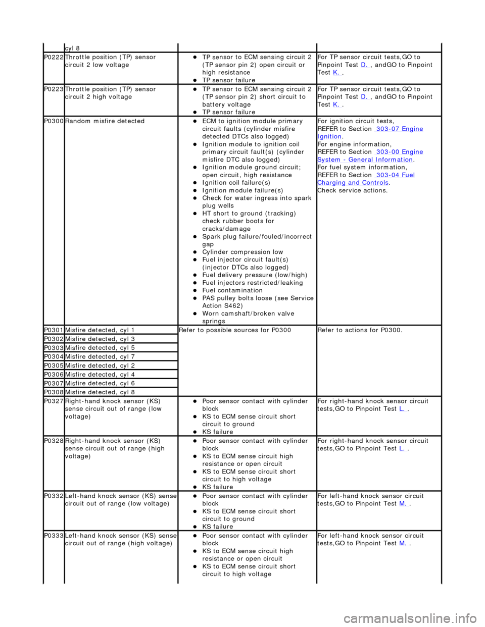
cyl 8
P0222Thro
ttle position (TP) sensor
circuit 2 low voltage
TP se
nsor to ECM sensing circuit 2
(TP sensor pin 2) open circuit or
high resistance
TP sensor
failure
F
or TP sensor circ
uit tests,GO to
Pinpoint Test D.
, andG
O to Pinpoint
Test K.
.
P0223Thro
ttle position (TP) sensor
circuit 2 high voltage
TP se
nsor to ECM sensing circuit 2
(TP sensor pin 2) short circuit to
battery voltage
TP sensor
failure
F
or TP sensor circ
uit tests,GO to
Pinpoint Test D.
, andG
O to Pinpoint
Test K.
.
P0300Ran
dom misfire detected
ECM to
ignition module primary
circuit faults (cylinder misfire
detected DTCs also logged)
Igni
tion module to ignition coil
primary circuit fault(s) (cylinder
misfire DTC also logged)
Ignition modu
le ground circuit;
open circuit, hi gh resistance
Ignition coil
failure(s)
Ignition modul
e failure(s)
Check f
or water ingress into spark
plug wells
HT sho
rt to ground (tracking)
check rubber boots for
cracks/damage
Spark plug
failure/fouled/incorrect
gap
Cy
linder compression low
F
uel injector circuit fault(s)
(injector DTCs also logged)
F
uel delivery pressure (low/high)
F
uel injectors restricted/leaking
Fuel contamination
P
AS pulley bolts loose (see Service
Action S462)
W
orn camshaft/broken valve
springs
F
or ignition circuit tests,
REFER to Section 303
-07
Engine
Ignition.
F
or engine information,
REFER to Section 303
-00
Engine
Sy
stem
- General
Information
.
F
or fuel system information,
REFER to Section 303
-04
Fuel
Charging and Con
trols
.
Check service
actions.
P0301Mis
fire detected, cyl 1
R
efer to possible sources for P0300
R
efer to actions for P0300.
P0302Mis
fire detected, cyl 3
P0303Mis
fire detected, cyl 5
P0304Mis
fire detected, cyl 7
P0305Mis
fire detected, cyl 2
P0306Mis
fire detected, cyl 4
P0307Mis
fire detected, cyl 6
P0308Mis
fire detected, cyl 8
P0327Right
-hand knock sensor (KS)
sense circuit out of range (low
voltage)
Poor sensor cont
act with cylinder
block
KS to
ECM sense circuit short
circuit to ground
KS fai
lure
F
or right-hand knock sensor circuit
tests,GO to Pinpoint Test L.
.
P0328Right
-hand knock sensor (KS)
sense circuit out of range (high
voltage)
Poor sensor cont
act with cylinder
block
KS to EC
M sense circuit high
resistance or open circuit
KS to
ECM sense circuit short
circuit to high voltage
KS fai
lure
F
or right-hand knock sensor circuit
tests,GO to Pinpoint Test L.
.
P0332Left-hand knock sens
or (KS) sense
circuit out of range (low voltage)
Poor sensor cont
act with cylinder
block
KS to
ECM sense circuit short
circuit to ground
KS fai
lure
F
or left-hand knoc
k sensor circuit
tests,GO to Pinpoint Test M.
.
P0333Left-hand knock sens
or (KS) sense
circuit out of range (high voltage)
Poor sensor cont
act with cylinder
block
KS to EC
M sense circuit high
resistance or open circuit
KS to
ECM sense circuit short
circuit to high voltage
F
or left-hand knoc
k sensor circuit
tests,GO to Pinpoint Test M.
.