engine JAGUAR X308 1998 2.G Workshop Manual
[x] Cancel search | Manufacturer: JAGUAR, Model Year: 1998, Model line: X308, Model: JAGUAR X308 1998 2.GPages: 2490, PDF Size: 69.81 MB
Page 1255 of 2490

E
lectronic Engine Controls - Knock
Sensor (KS) RH4.0L SC V8 - AJ26
Re
moval and Installation
Remov
al
Installation
1.
R
emove supercharger; refer to 18.50.15.
2. Remove knock sensor from engine.
пЃ¬De
tach connector and disconnect.
пЃ¬R
emove knock sensor.
1. Installation is a reversal of the removal procedure.
2. Tighten sensor to 31 - 41 Nm.
Page 1256 of 2490
El
ectronic Engine Controls -
Mass Air Flow (MAF) Sensor
Remo
val and Installation
Remov
a
l
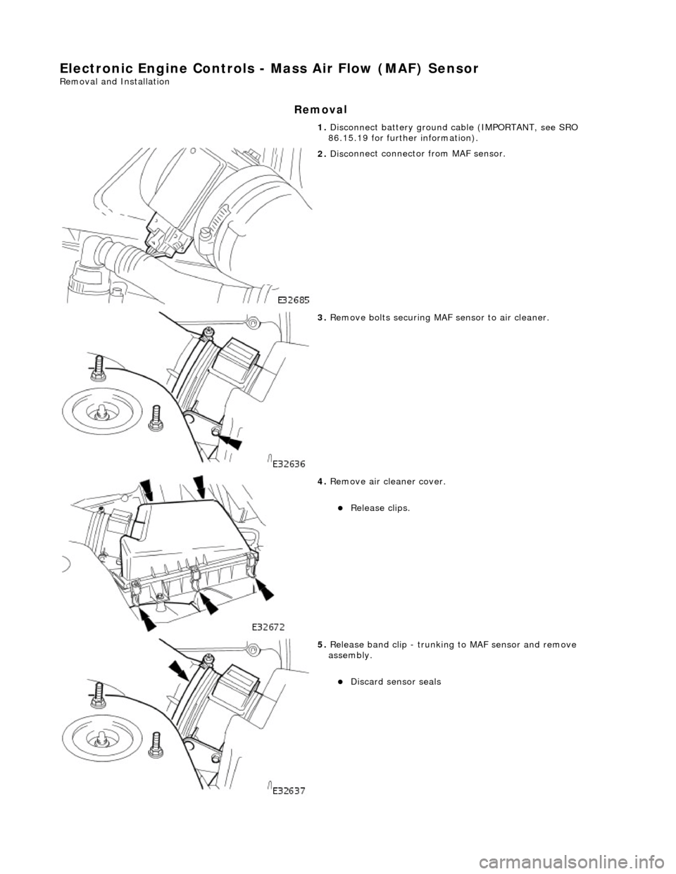
1.
Disc onne
ct battery ground cable (IMPORTANT, see SRO
86.15.19 for further information).
2. Disc
onnect connector from MAF sensor.
3. Re
move bolts securing MAF sensor to air cleaner.
4. Re
move air cleaner cover.
пЃ¬Re
lea
se clips.
5. Re
lease band clip - trunking to MAF sensor and remove
assembly.
пЃ¬Di sc
ard sensor seals
Page 1258 of 2490

El
ectronic Engine Controls - Variable
Camshaft Timing (VCT) Oil Control
Solenoid
Re mo
val and Installation
Remova
l
1.
Op
en the engine compartment and fit paintwork protection
sheets.
2. Disc
onnect the batt
ery ground cable.
пЃ¬Re
move the battery cover.
3. Disc
onnect the VVT solenoid connector.
4. Re
move the two bolts which secure the VVT solenoid to the
timing cover.
5. Pull the VVT solenoid clear and discard the O-ring.
Page 1260 of 2490
Automatic Transmission/Transaxle - 4.0L NA V8 - AJ27/3.2L NA V8 - AJ26
-
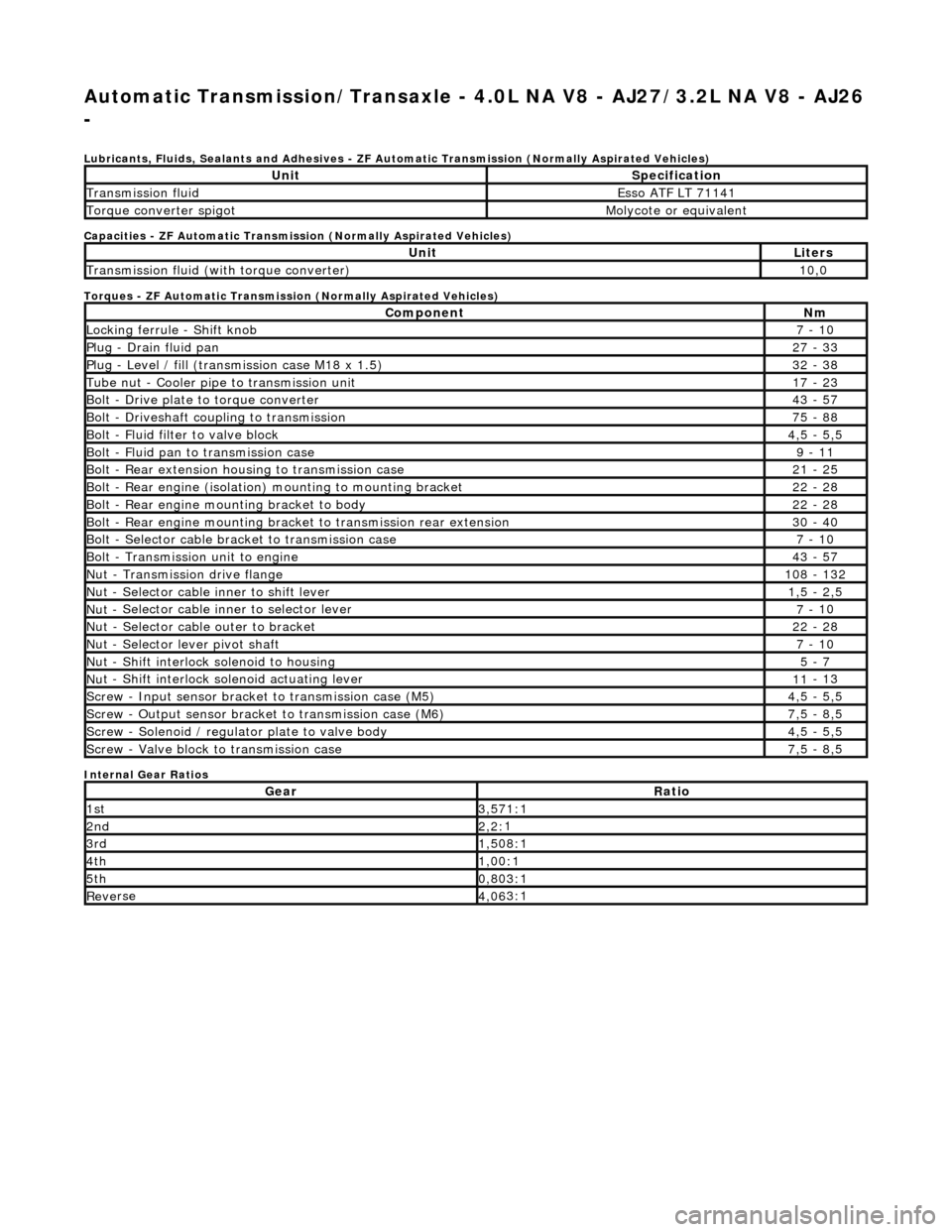
Lubri c
ants, Fluids, Sealants and Adhesives - ZF Au
tomatic Transmission (Normally Aspirated Vehicles)
Capacities - ZF Automatic Transmission (Normally Aspirated Vehicles)
Torques - ZF Automatic Transmission (Normally Aspirated Vehicles)
Internal Gear Ratios
UnitS p
ecification
Transmissi
on fluidEsso
ATF LT 71141
Torque converter spigotMolyc
o
te or equivalent
UnitLi
t
ers
Transmissi
on fluid (with
torque converter)
10
,0
Com p
onent
Nm
Locki
n
g ferrule - Shift knob
7 -
10
P
l
ug - Drain fluid pan
27
-
33
P
l
ug - Level / fill (transmission case M18 x 1.5)
32
-
38
Tu
be
nut - Cooler pipe to transmission unit
17
-
23
B
o
lt - Drive plate to torque converter
43
-
57
B
o
lt - Driveshaft coupling to transmission
75
-
88
Bo
lt
- Fluid filter to valve block
4,
5 -
5,5
Bolt
-
Fluid pan to transmission case
9 -
11
B
o
lt - Rear extension housing to transmission case
21
-
25
Bolt
-
Rear engine (isolation) mounting to mounting bracket
22
-
28
Bolt -
Rear engine moun
ting bracket to body
22
-
28
Bolt
-
Rear engine mounting bracke
t to transmission rear extension
30 -
40
B
o
lt - Selector cable bracket to transmission case
7 -
10
Bolt
-
Transmission unit to engine
43
-
57
Nu
t -
Transmission drive flange
1
08 -
132
Nu
t -
Selector cable inner to shift lever
1,
5 -
2,5
Nu
t -
Selector cable inner to selector lever
7 -
10
Nu
t -
Selector cable outer to bracket
22
-
28
Nu
t
- Selector lever pivot shaft
7 -
10
Nu
t -
Shift interlock solenoid to housing
5 -
7
Nut -
Shift interlock solenoid actuating lever
11
-
13
Sc
re
w - Input sensor bracket to transmission case (M5)
4,
5 -
5,5
Screw
-
Output sensor bracket to transmission case (M6)
7,
5 -
8,5
Screw
-
Solenoid / regulator plate to valve body
4,
5 -
5,5
Sc
re
w - Valve block to transmission case
7,
5 -
8,5
GearRatio
1s
t3,57
1:1
2n
d2,2:
1
3r
d1,50
8:1
4t
h1,00
:1
5t
h0,80
3:1
Re
ve
rse
4,
06
3:1
Page 1261 of 2490
Automatic Transmission/Transaxle - 4.0L NA V8 - AJ27/3.2L NA V8 - AJ26
- Transmission Descriptio
n
Description an
d Operation
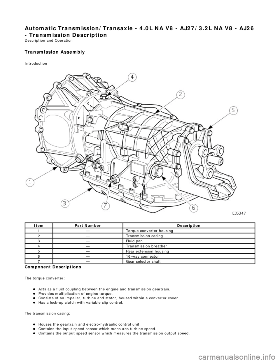
Transmission As
sembly
Int
roduction
Compon
ent Descriptions
The t
orque converter:
пЃ¬Acts as a fluid
coupling between the
engine and transmission geartrain.
пЃ¬P
rovides multiplication of engine torque.
пЃ¬Cons
ists of an impeller, turbine and stat
or, housed within a converter cover.
пЃ¬Has a l
ock-up clutch with variable slip control.
The transmission casing:
пЃ¬Houses the geartrain and elec t
ro-hydraulic control unit.
пЃ¬Contains
the input speed sensor which measures turbine speed.
пЃ¬Contai
ns the output speed sensor which measures the transmission output speed.
It
em
Par
t Number
De
scription
1—Torque c
onverter housing
2—Tran
smission casing
3—Fluid pan
4—Transmission bre
ather
5—Re
ar extension housing
6—16
-way connector
7—Gear s
elector shaft
Page 1262 of 2490
пЃ¬Contains th
e hydraulic system pump.
пЃ¬Contains
th
e fluid temperature sensor.
The epicyclic geartrain:
пЃ¬Provi des fi
ve forward gears and Reverse.
пЃ¬Has
h
ydraulically actuated, multi-disk clutches, to select the required gear ratios.
пЃ¬Feature
s clutch-to-clutch operation to permit
gear shifts for uninterrupted power flow.
The electro-hydraulic control unit:
пЃ¬Is lo c
ated in the lower part of
the unit, within the fluid pan.
пЃ¬Is controlled
by the TCM (transmissio
n control module), and the manual selector valve which is cable operated.
пЃ¬Re
gulates the flow of fluid to the ge
artrain clutches via three solenoid-operated valv es and the manual selector
valve.
пЃ¬Has fi ve pressure
regulators for controll
ing fluid pressures within the system.
пЃ¬Is con
nected to the TCM via a 16-way connector mounted on
the left-hand side of the transmission casing. Refer to
Connector Pins Identification, Section 307-01A.
The hydraulic system pump:
пЃ¬Is l o
cated at the front of the transmission casing.
пЃ¬Is dri
v
en from the impeller hub,
pressurising the fluid whenever the engine is running.
пЃ¬Supplie
s fluid under pressure to the torq
ue converter, geartrain, electro-hydr aulic control unit and the lubrication
circuit.
пЃ¬D r
aws fluid from the fluid pa
n below the transmission casing, through a filter.
The rear extension housing:
пЃ¬Is bolt
ed to the rear of the transmission casing.
пЃ¬Provides the rear engine / transmi
ssion mo
unting point; refer to section 303-01.
пЃ¬Carrie
s the transmission output shaft oil seal.
Filled-for-l
i
fe Fluid System
The
transm
ission is 'filled for life' and
does not require fluid changes, except where extreme driving conditions prevail.
Routine level checking is not required and a dipstick is not pr ovided. A level / filler plug is fitted for level checking and
replenishment, following service actions; see 303-01 General Procedures.
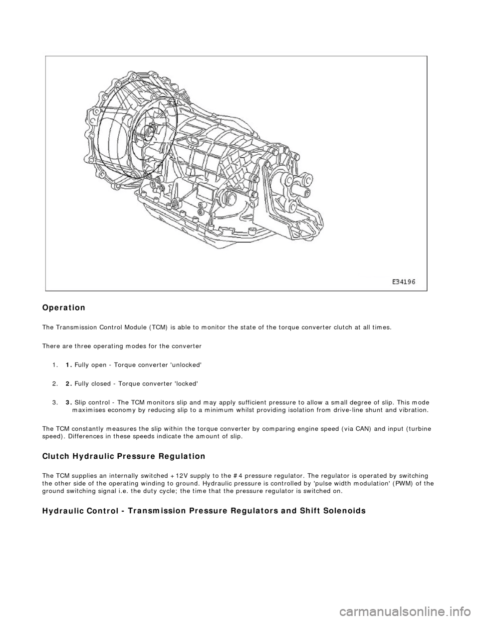
Transmission Torque Converter
Page 1263 of 2490
Op
eration
The T
ransmission Control Module (TCM) is
able to monitor the state of the torque converter clut ch at all times.
There are three operating modes for the converter
1. 1. Fully open - Torque converter 'unlocked'
2. 2. Fully closed - Torque converter 'locked'
3. 3. Slip control - The TCM monitors slip and may apply sufficie nt pressure to allow a small degree of slip. This mode
maximises economy by reducing slip to a minimum whilst providing isolation from drive-line shunt and vibration.
The TCM constantly measures the slip within the torque conver ter by comparing engine speed (via CAN) and input (turbine
speed). Differences in these speeds indicate the amount of slip.
Clutch Hydraulic Pressure Regulation
The T
CM supplies an internally switched +1
2V supply to the #4 pressure regulator. The regulator is operated by switching
the other side of the operating winding to ground. Hydraulic pressure is controlled by 'pulse width modulation' (PWM) of the
ground switching signal i.e. the duty cycle; the time that the pressure regulator is switched on.
Hydraulic Control
- Transmission Pre
ssure Regulators an d Shift Solenoids
Page 1266 of 2490

Operation
The transmission fluid temperature sensor is integrated into the internal harness within the fluid pan.
It should be noted that this component is not serviceable, ne cessitating the renewal of the internal harness should a fault
occur.
Following engine start-up, if the fluid temperature is < 20 В°C and does not increase by 10 В°C after 180 seconds, a failure
judgement is made. A similar judgement is made should the temperature change by more than 5 В°C in <100 milliseconds.
The MIL is illuminated if the failure judgement is made on two successive trips.
Sensor output is continuously monitored for out of range values. If a sustained high, or low inpu t is sensed, indicating a
harness or connector fault, a failure judgement is made.
Location of Sensor Within The Harness
Temperature / Resistance Relationship Chart
Page 1268 of 2490
Input speed is monitored by the TCM with a rationality check being made against output speed. A fault will be flagged if the
indicated input speed exceeds 7400 rpm. Additionally, a failure judgement will be made if the indicated input speed is <160
rpm with engine speed >608 rpm and output speed >224 rpm
The procedure is similar for the output sp eed diagnostic. A fault (non OBDII) will be flagged if the indicated input speed
exceeds 6712 rpm. Additionally a failure judgement will be ma de if the indicated output speed is <160 rpm and the average
road wheel speed exceeds 100 rpm.
Under normal circumstance s after the output speed diagnost ic fault code has been set, the TCM uses rear wheel speed
information to compute its calculations, this has no effect on transmission operation. However, should a second fault occur,
in the ABS system, thus making rear wheel speed information unavailable, an additional fault code will be logged.
Control Systems
Introduction
Gear selection is achieved by controlling the flow of transmission fluid to internal multi-disc clutches.
The three solenoid valves direct the transmission fluid flow to the selected clutches and the pressure regulators control the
fluid pressure to each component. One pr essure regulator serves as a master pressure control for the entire system and a
second is used exclusively for torque converter clutch lock-up operation.
The TCM controls the internal components thus determining gear selection and shift pattern.
In the event of an electronic system fault the basic function s Park, Reverse Neutral and Drive Fourth are retained by the
hydraulic system.
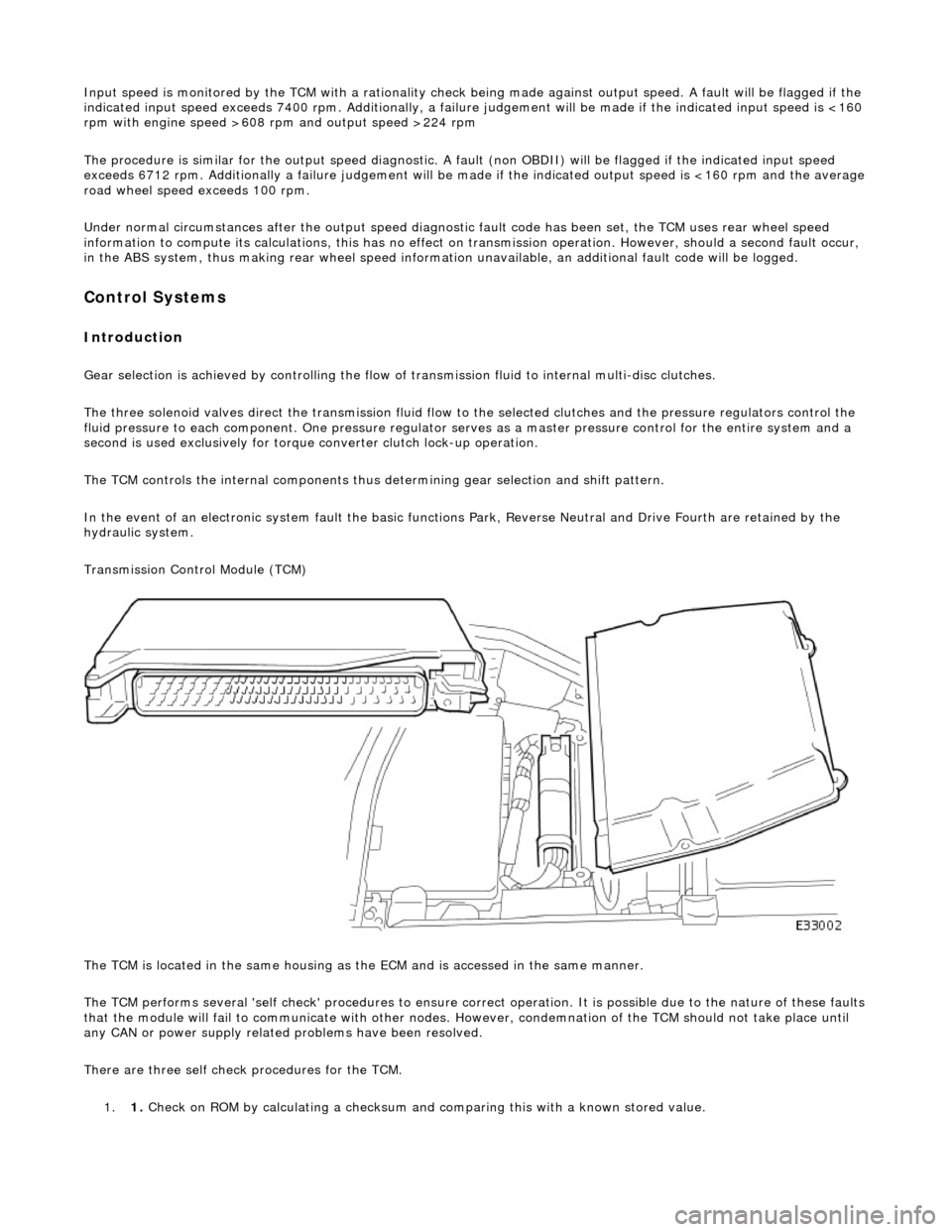
Transmission Control Module (TCM)
The TCM is located in the same housing as th e ECM and is accessed in the same manner.
The TCM performs several 'self check' procedur es to ensure correct operation. It is possible due to the nature of these faults
that the module will fail to communicate with other nodes. However, condemnation of the TCM should not take place until
any CAN or power supply related problems have been resolved.
There are three self check procedures for the TCM. 1. 1. Check on ROM by calculatin
g a checksum and comparing this with a known stored value.
Page 1269 of 2490
2.2. Check on non-volatile diagnostic memory by wr iting a test pattern and then reading it back.
3. 3. Internal 'watchdog' hardware to check whether the TCM has crashed.
Transmission Control Module Supply Voltage
The TCM monitors battery and igni tion switched supply voltages.
A permanent supply is used to maintain a battery backed 'memor y'. Should this supply be cut, due to battery disconnection
perhaps, the 'adaptive shift' valu es will be lost. This will result in a small reduction in shift quality for a period until th e
adaptions are 're-learned'
The TCM will adopt 'limp home' mode as a result of the supply voltage being >16V or <7V with an engine speed >1600
rpm.
Should the ignition supply be >7V but <9V the TCM will hold the gear that it has currently selected. If after 2.5 seconds,
with the engine speed >1600 rpm, the voltage remains at this level, 'limp home' mode will be adopted. The 2.5 second
delay is built in to prevent reaction to a momentary voltage fluctuation.
Operation
CAUTION: Disconnection of the TCM and / or the vehicle batt ery will cause system adaptions to be lost; this may be
apparent by shift quality degradation. Fo llowing reconnection, a period of 'varied' driving will reinstate adaptions and thus
normal operation. Please ensure that the customer is made aware that the adaption period is variable and may occur after
handover, as the transmission re-learns the prevailing driving style.
• NOTE: Should the TCM fail, please ensure that the control housing cooling fan is operating correctly. Failure of the cooling
fan MUST be rectified before renewing the TCM and details of a fan fa ilure should accompany the returned TCM.
The TCM processes information received in both analogue and digital form, such as:
пЃ¬Transmission input speed пЃ¬Transmission output speed пЃ¬Throttle position пЃ¬Pedal demand пЃ¬Gear selector position пЃ¬Engine torque пЃ¬Engine speed пЃ¬Transmission oil temperature пЃ¬Mode switch
This information is then used by the TC M to control shift energy management and decide which shift program to implement
and which gear to select.
The TCM uses the various sensors and inpu ts to monitor the correct operation of the system an d is programmed to take
default action and inform the operator when a fault occurs.
Safety Functions
The safety functions are designed to safeguard against inappr opriate actions by the operator as well as against system
malfunctions. The system prevents reve rse gear from being engaged at high forward speeds and prevents manual
downshifting at excessive engine speeds; these functions are not operational in mechanical limp-home mode.
The TCM constantly monitors the transmissi on for faults. In the event of a problem the TCM will adopt a 'limp home' mode
in which only P R N D - (selector in D but only fourth gear is enabled) are available. The operator will be made aware of
certain faults by an in strument panel warning.
The electrical and diagnostic system has been designed such that system integrity is protected at all times, the safety
concept being based on th e following three points: