engine JAGUAR X308 1998 2.G Workshop Manual
[x] Cancel search | Manufacturer: JAGUAR, Model Year: 1998, Model line: X308, Model: JAGUAR X308 1998 2.GPages: 2490, PDF Size: 69.81 MB
Page 1394 of 2490
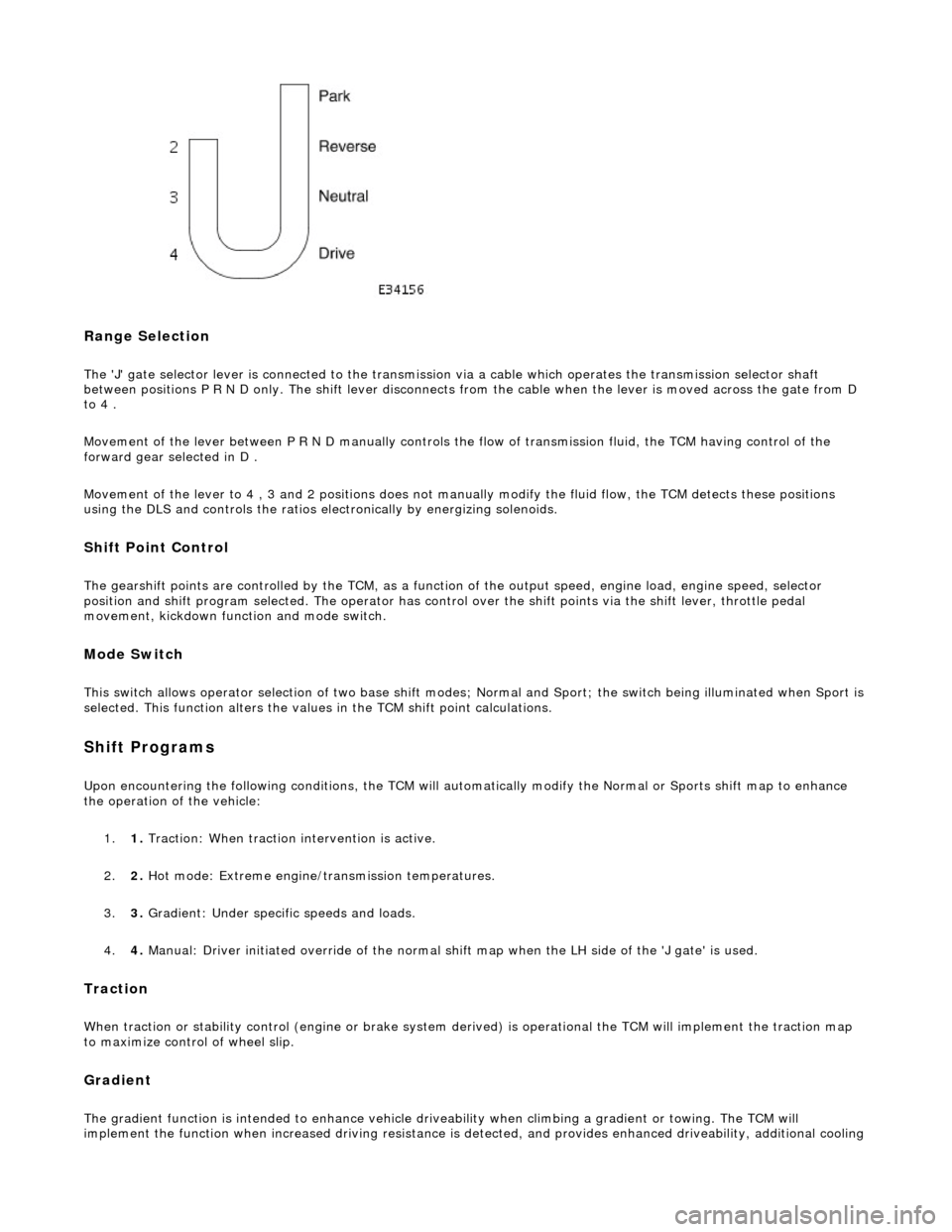
Range Selection
The 'J' gate selector lever is connected to the transmission via a cable which operates the transmission selector shaft
between positions P R N D only. The shift lever disconnects from the cable when the lever is moved across the gate from D
to 4 .
Movement of the lever between P R N D manu ally controls the flow of transmission fluid, the TCM having control of the
forward gear selected in D .
Movement of the lever to 4 , 3 and 2 positions does not manu ally modify the fluid flow, the TCM detects these positions
using the DLS and controls the ratios electronically by energizing solenoids.
Shift Point Control
The gearshift points are controlled by the TCM, as a function of the output speed, engine load, engine speed, selector
position and shift program selected. The operator has control over the shift points via the shift lever, throttle pedal
movement, kickdown function and mode switch.
Mode Switch
This switch allows operator selection of two base shift modes; Normal and Sport; th e switch being illuminated when Sport is
selected. This function alters the values in the TCM shift point calculations.
Shift Programs
Upon encountering the following conditions, the TCM will auto matically modify the Normal or Sports shift map to enhance
the operation of the vehicle:
1. 1. Traction: When traction intervention is active.
2. 2. Hot mode: Extreme engine/transmission temperatures.
3. 3. Gradient: Under specific speeds and loads.
4. 4. Manual: Driver initiated override of the normal shif t map when the LH side of the 'J gate' is used.
Traction
When traction or stability control (engine or brake system de rived) is operational the TCM will implement the traction map
to maximize control of wheel slip.
Gradient
The gradient function is intended to enhance vehicle drivea bility when climbing a gradient or towing. The TCM will
implement the function when increased driving resistance is de tected, and provides enhanced driveability, additional cooling
Page 1396 of 2490
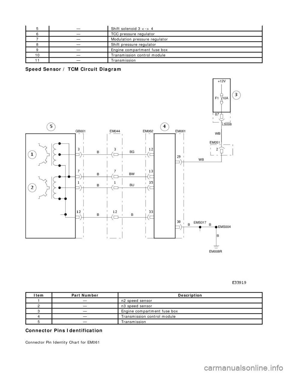
Speed Sensor / TCM Circuit Diagram
Connector Pins Identification
Connector Pin Identity Chart for EM061
5—Shift solenoid 3 <-> 4
6—TCC pressure regulator
7—Modulation pressure regulator
8—Shift pressure regulator
9—Engine compartment fuse box
10—Transmission control module
11—Transmission
ItemPart NumberDescription
1—n2 speed sensor
2—n3 speed sensor
3—Engine compartment fuse box
4—Transmission control module
5—Transmission
Page 1405 of 2490

Pinpoint test C: P0702, P0753, P0758, P0763
Connect the scan tool 1
Have the DTC(s) and freeze frame data been recorded?
Yes GO to B2
B2: RENEW TORQUE CONVERTER
Renew the torque converter 1
Has the torque converter been renewed?
Yes GO to B3
B3: END
Drive the vehicle for a period from cold to include idle, brisk
acceleration and steady state cruising up to and including
normal engine temperature. Check for the presence of DTC 1
Has the fault code cleared?
Yes STOP
No Contact Jaguar Service
PINPOINT TEST C : P0702, P0753, P0758, P0763
TEST CONDITIONSDETAILS/RESULTS/ACTIONS
C1: RETRIEVE DTCS
• NOTE: Battery and or ECM disconnection prior to scanning wi ll erase all data, ensure that the correct DTC is present.
Connect the scan tool 1
Have the DTC(s) and freeze frame data been recorded?
Yes GO to C2
C2: CHECK HARNESS +VE CONTINUITY
Page 1412 of 2490
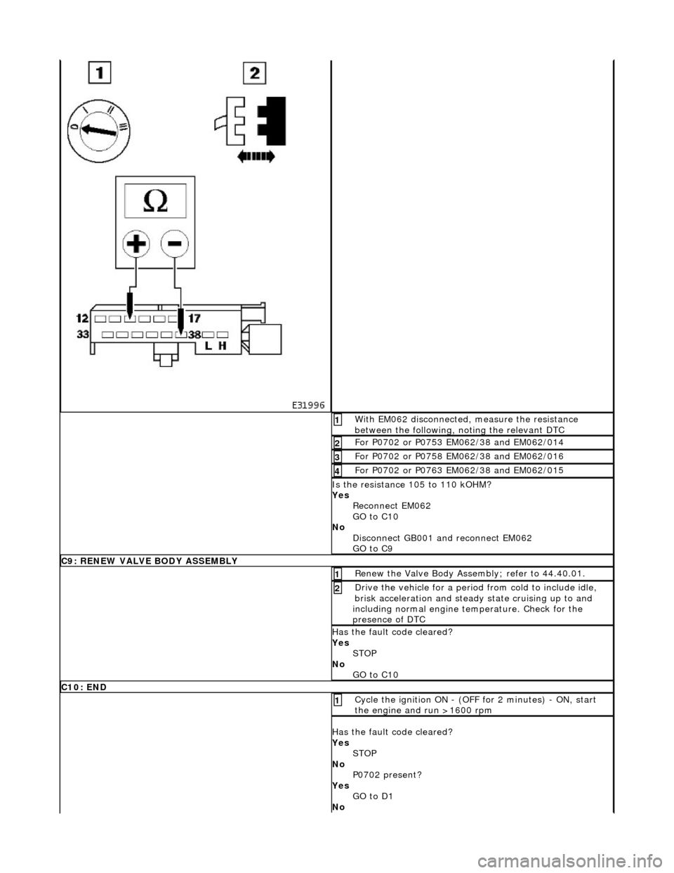
With EM062 disconnected, measure the resistance
between the following, noting the relevant DTC 1
For P0702 or P0753 EM062/38 and EM062/014 2
For P0702 or P0758 EM062/38 and EM062/016 3
For P0702 or P0763 EM062/38 and EM062/015 4
Is the resistance 105 to 110 kOHM?
Yes Reconnect EM062
GO to C10
No Disconnect GB001 and reconnect EM062
GO to C9
C9: RENEW VALVE BODY ASSEMBLY
Renew the Valve Body Assembly; refer to 44.40.01. 1
Drive the vehicle for a period from cold to include idle,
brisk acceleration and steady state cruising up to and
including normal engine temperature. Check for the
presence of DTC 2
Has the fault code cleared?
Yes STOP
No GO to C10
C10: END
Cycle the ignition ON - (OFF for 2 minutes) - ON, start
the engine and run >1600 rpm 1
Has the fault code cleared?
Yes STOP
No P0702 present?
Yes GO to D1
No
Page 1419 of 2490

Pinpoint test E: P0702
With EM062 disconnected, measure the resistance
between the following, noting the relevant DTC 1
For P0702 or P0748 EM062/38 and EM062/036 2
For P0702 or P1748 EM062/38 and EM062/037 3
Is the resistance 16 to 18 kOHM?
Yes Reconnect EM062
GO to D9
No Renew the Valve Body Assembly; refer to 44.40.01.
Drive the vehicle for a period from cold to include idle,
brisk acceleration and steady state cruising up to and
including normal engine temperature.
GO to D9
D9: END
Cycle the ignition ON - (OFF for 2 minutes) - ON, start
the engine and run >1600 rpm 1
Has the fault code cleared?
Yes STOP
No Contact Jaguar Service
PINPOINT TEST E : P0702
TEST CONDITIONSDETAILS/RESULTS/ACTIONS
E1: RETRIEVE DTCS
• NOTE: Battery and or ECM disconnection prior to scanning wi ll erase all data, ensure that the correct DTC is present.
Page 1427 of 2490

Pinpoint test H: P0730, P0780
Connect the scan tool 1
Have the DTC(s) and freeze frame data been recorded?
Yes GO to G2
G2: RENEW TCM
Renew the TCM 1
Has the TCM been renewed?
Yes GO to G3
G3: END
• NOTE: The following step must be carried out in order that sy stem adaptions can take place.
Drive the vehicle for a period from cold to include idle, brisk
acceleration and steady state cruising up to and including
normal engine temperature. Check for the presence of DTC 1
Has the fault code cleared?
Yes STOP
No Contact Jaguar Service
PINPOINT TEST H : P0730, P0780
TEST CONDITIONSDETAILS/RESULTS/ACTIONS
H1: RETRIEVE DTCS
• NOTE: Battery and or ECM disconnection prior to scanning wi ll erase all data, ensure that the correct DTC is present.
Connect the scan tool 1
Have the DTC(s) and freeze frame data been recorded?
Yes GO to H2
H2: RENEW VALVE BODY ASSEMBLY
Renew the valve body assembly 1
Drive the vehicle for a period from cold to include idle, brisk
acceleration and steady state cruising up to and including
normal engine temperature. Check for the presence of DTC 2
Has the fault code cleared?
Page 1430 of 2490
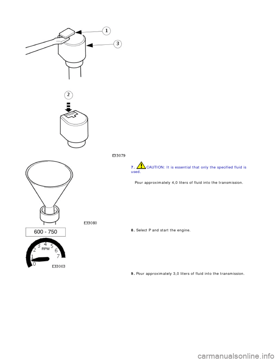
7. CAUTION: It is essential that only the specified fluid is
used.
Pour approximately 4,0 liters of fluid into the transmission.
8. Select P and start the engine.
9. Pour approximately 3,0 liters of fluid into the transmission.
Page 1431 of 2490
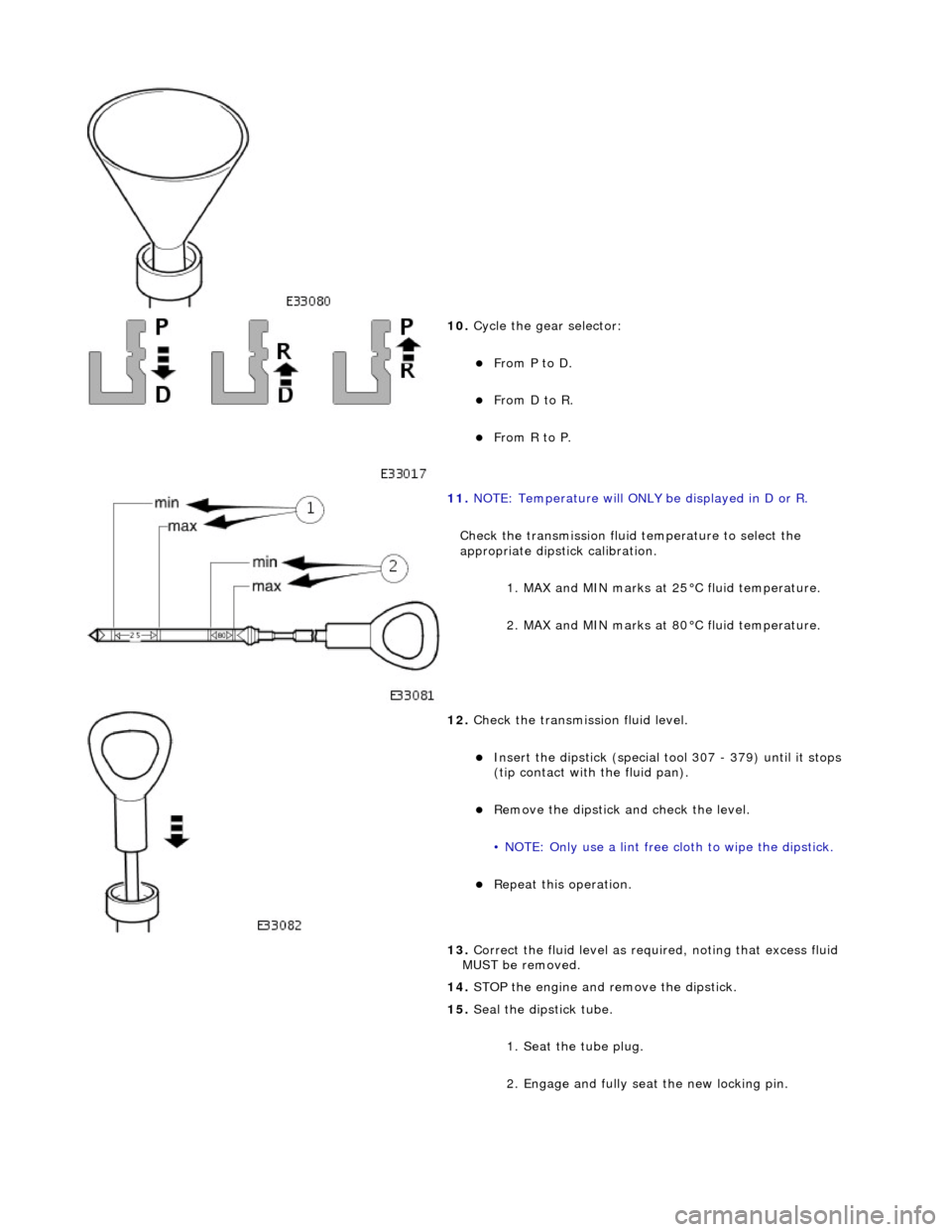
10. Cycle the gear selector:
пЃ¬From P to D.
пЃ¬From D to R.
пЃ¬From R to P.
11. NOTE: Temperature will ONLY be displayed in D or R.
Check the transmission fluid temperature to select the
appropriate dipstick calibration. 1. MAX and MIN marks at 25В°C fluid temperature.
2. MAX and MIN marks at 80В°C fluid temperature.
12. Check the transmission fluid level.
пЃ¬Insert the dipstick (special tool 307 - 379) until it stops
(tip contact with the fluid pan).
пЃ¬Remove the dipstick an d check the level.
• NOTE: Only use a lint free cloth to wipe the dipstick.
пЃ¬Repeat this operation.
13. Correct the fluid leve l as required, noting that excess fluid
MUST be removed.
14. STOP the engine and remove the dipstick.
15. Seal the dipstick tube.
1. Seat the tube plug.
2. Engage and fully seat the new locking pin.
Page 1433 of 2490

Automatic Transmission/Transaxle - 4.0L SC V8 - AJ26 - Extension
Housing Seal
In-vehicle Repair
Removal
Special Tool(s)
Oil seal replacer
307-378
Driveshaft wrench
205-053
1. Disconnect the battery ground lead.
2. Select N and choc the road wheels.
3. Remove the front muffler, re fer to Operation 30.10.18.
4. Remove the engine rear mounting bracket.
1. Support the transmission.
2. Remove the bolt, engine rear mounting to transmission.
3. Remove the four bolts which secure the mounting
cross member to the body.
5. Detach the driveshaft from th e transmission drive flange.
1. If the transmission is to be refitted, mark the position of the coupling relative to the drive flange.
5. CAUTION: Under no circ umstances remove the
driveshaft to flexible coupling fixings.
2. Remove the three bolts, tr ansmission drive flange to
flexible coupling.
6. Secure the driveshaft wrench 205 - 053 to the output shaft
flange.
Page 1443 of 2490

Automatic Transmission/Transaxle - 4.0L SC V8 - AJ26 - Transmission
Internal Wiring Harness Electr ical Connector O-Ring Seals
In-vehicle Repair
Removal
1. Disconnect the batt ery ground cable.
2. Open the engine compartment and fit paint protection sheets.
3. Raise the vehicle for access.
4. WARNING: TRANSMISSION FLUID MAY CAUSE SEVERE
BURNS, ENSURE THAT ALL SAFET Y PROCEDURES ARE OBSERVED
AND THAT THE RECEPTACLE FOR WASTE HAS SUFFICIENT
CAPACITY.
Drain the transmission fluid.
пЃ¬Carefully remove the drain pl ug and discard the sealing
washer.
5. Remove the harness heatshield lower fixing.
пЃ¬Remove the screw heatshield / fluid pan clamp.
6. Remove the harness heatshield.
пЃ¬Pull the heatshield from under the clip.
7. Disconnect the transmission link harness connector.
1. Release the locking lever on the guide bush and disconnect the harness connector.