engine JAGUAR X308 1998 2.G Workshop Manual
[x] Cancel search | Manufacturer: JAGUAR, Model Year: 1998, Model line: X308, Model: JAGUAR X308 1998 2.GPages: 2490, PDF Size: 69.81 MB
Page 1332 of 2490

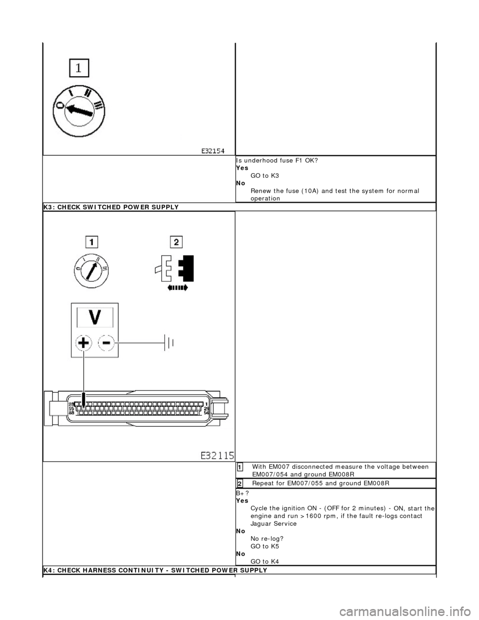
Is underhood fuse F1 OK?
Yes GO to K3
No Renew the fuse (10A) and te st the system for normal
operation
K3: CHECK SWITCHED POWER SUPPLY
With EM007 disconnected measure the voltage between
EM007/054 and ground EM008R 1
Repeat for EM007/055 and ground EM008R 2
B+?
Yes Cycle the ignition ON - (OFF for 2 minutes) -
ON, start the engine and run >1600 rpm, if the fault re-logs contact
Jaguar Service
No No re-log?
GO to K5
No GO to K4
K4: CHECK HARNESS CONTINUITY - SWITCHED POWER SUPPLY
Page 1336 of 2490

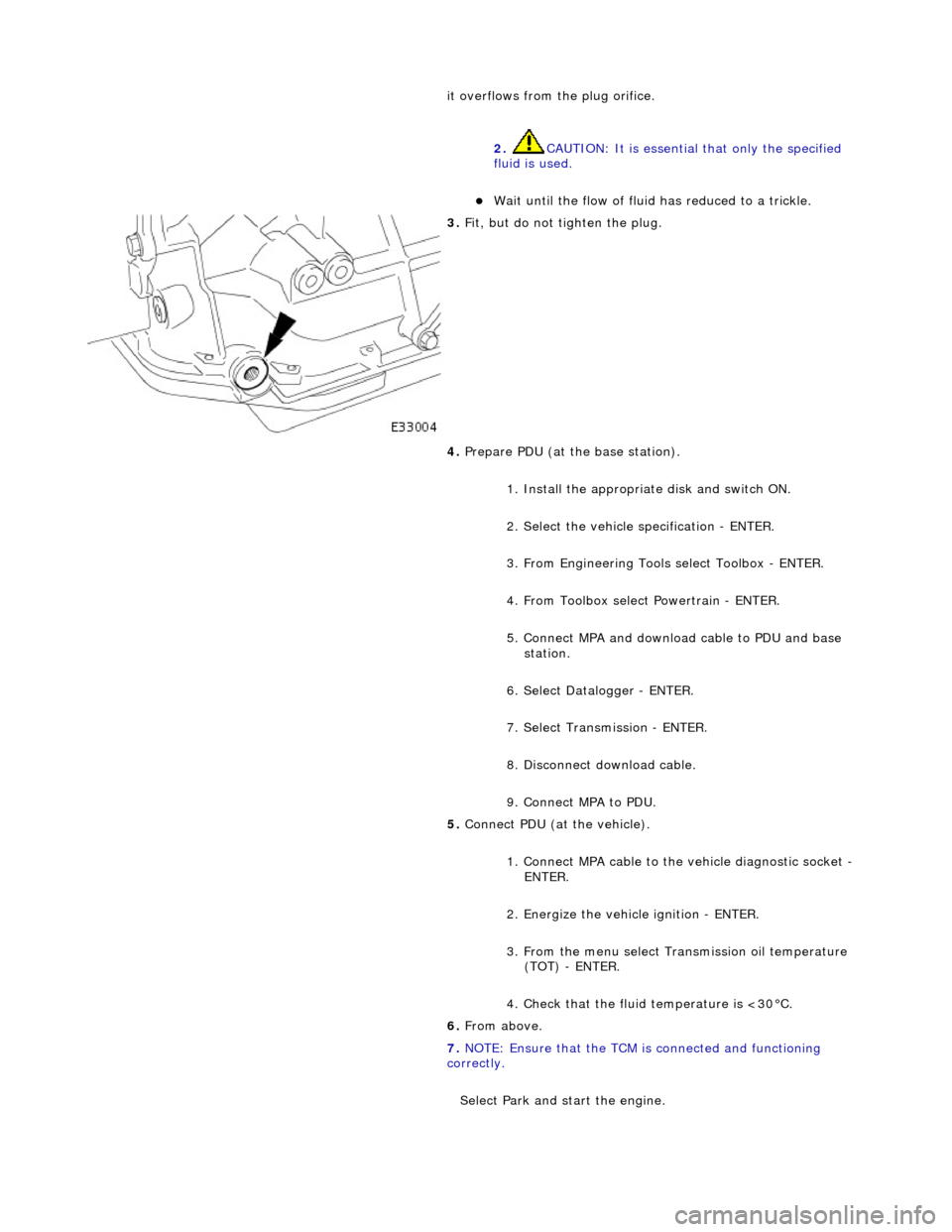
it overflows from the plug orifice. 2. CAUTION: It is essential that only the specified
fluid is used.
пЃ¬Wait until the flow of fluid has reduced to a trickle.
3. Fit, but do not tighten the plug.
4. Prepare PDU (at the base station).
1. Install the appropriat e disk and switch ON.
2. Select the vehicle specification - ENTER.
3. From Engineering Tools select Toolbox - ENTER.
4. From Toolbox select Powertrain - ENTER.
5. Connect MPA and download cable to PDU and base station.
6. Select Datalogger - ENTER.
7. Select Transmission - ENTER.
8. Disconnect download cable.
9. Connect MPA to PDU.
5. Connect PDU (at the vehicle).
1. Connect MPA cable to the vehicle diagnostic socket -
ENTER.
2. Energize the vehicle ignition - ENTER.
3. From the menu select Transmission oil temperature (TOT) - ENTER.
4. Check that the fluid temperature is <30В°C.
6. From above.
7. NOTE: Ensure that the TCM is connected and functioning
correctly.
Select Park and start the engine.
Page 1345 of 2490

Automatic Transmission/Transaxle - 4.0L NA V8 - AJ27/3.2L NA V8 - AJ26
- Extension Housing O-Ring Seal
In-vehicle Repair
Removal
1. Select N position.
2. Raise the vehicle for access.
3. Remove the front muffler, 30.10.18.
4. Locate a transmission jack, Epco V-100 or similar, under the
transmission unit.
пЃ¬Adjust the angle of the jack to suit the transmission.
пЃ¬Secure the side clamps.
пЃ¬Pass the safety chain over the transmission unit and
secure.
пЃ¬Take the weight of the transmission and engine.
5. Remove the engine rear mounting bracket.
1. Remove the engine rear mounting to bracket bolt.
2. Remove the mounting bracket to body bolts.
6. Gently lower the transmission jack.
7. CAUTION: Under no circumstan ces remove the driveshaft
to flexible coupling fixings.
Detach the driveshaft fro m the transmission unit.
пЃ¬Mark the position of the coupling to drive flange.
пЃ¬Remove the three bolts which secure the transmission
drive flange to the flexible coupling .
8. Remove the rear extension housing assembly.
1. Remove the ten bolts, noting their location for installation.
2. Remove and discard the O-ring.
Page 1346 of 2490

Installation
9. Clean the mating faces.
1. Installation is the reverse of the removal procedure noting
that;
1. Install a new O-ring seal.
2. Tighten the ten bolts to the specified torque figure.
2. Align the driveshaft with the tr ansmission drive flange using
the marks made on removal.
пЃ¬Tighten the three bolts to the specified torque figure.
3. Raise the transmission carefu lly to position, using the
transmission jack
4. Fit the engine rear mounting and tighten the centre bolt and
outer bolts to the specified torque figures.
пЃ¬Check that the safety chain on the transmission jack will
not be trapped when the mounting is fitted.
5. Remove the transmission jack.
Page 1357 of 2490

Automatic Transmission/Transaxle - 4.0L NA V8 - AJ27/3.2L NA V8 - AJ26
- Transmission Control Module (TCM)
In-vehicle Repair
Removal
1. Disconnect battery ground cable.
пЃ¬Remove the battery cover.
2. Remove the trim panel from the engine compartment,
passenger side.
1. Remove the left hand side enclosure panel.
2. If necessary, remove the centre trim panel.
3. Release the fixings and remove the cover from the ECM / TCM
housing.
4. Disconnect the TCM harness multiplug EM007.
5. Lift the TCM from its housing.
Page 1371 of 2490

Automatic Transmission/Transaxle - 4.0L NA V8 - AJ27/3.2L NA V8 - AJ26
- Transmission Support Insulator
In-vehicle Repair
Removal
Installation
1. Raise the vehicle on a ramp to a suitable height for working on
the rear mounting.
2. Remove the bolt which secure s the engine rear mounting
rubber to the transmission.
3. Position a transmission jack under the transmission casing.
Take the weight of the transmission on the jack.
4. Remove the rear mounting rubber.
1. Slacken the four bolt s which secure the rear
crossmember to the vehicle floor.
2. Remove the two bolts which secure the mounting rubber to the crossmember.
3. Remove the mounting rubber.
1. Fit the mounting rubber assembly to position and tighten the
centre bolt to 30-40 Nm .
2. Tighten the crossmember to body bolts and the mounting
rubber to crossmember bolts to 22-28 Nm.
Page 1375 of 2490

Automatic Transmission/Transaxle - 4.0L NA V8 - AJ27/3.2L NA V8 - AJ26
- Transmission
Removal
Removal
Special Tool(s)
Engine support
303-021
Engine lifting brackets
303-536
1. Select N gear position.
2. Open the engine compartment and fit paintwork protection
sheets.
3. Disconnect battery ground cable.
пЃ¬Remove the battery cover.
4. Remove the engine covers (12.30.06).
5. Remove the air intake tube, MAFM and air cleaner cover assy,
(19.10.30).
6. Install engine lifting bracket 303 - 536 at the rear RH.
7. Reposition the coolant he ader tank for access.
1. Remove the securing bolt.
Page 1376 of 2490

2. Reposition the tank.
8. Install engine lifting bracket 303 - 536 at the rear LH.
9. Support the engine using 303 - 021.
1. Adjust and locate the stan ds in the LH and RH fender
channels and tighten the beam fixings.
2. Engage the support hook s in the lifting brackets.
3. Tighten the support hook adjusters and take the weight of the engine.
10. Raise the vehicle for access.
11. Remove the LH downpipe cata lytic converter (17.50.09).
12. Remove the front muffler (30.10.18).
13. Remove the RH downpipe catalytic converter (17.50.09 and
17.50.10).
14. Drain the transmission fluid, (44.24.02).
15. Locate a transmission jack, Epco V-100 or similar, under the
transmission unit.
пЃ¬Adjust the angle of the jack to suit the transmission.
пЃ¬Secure the side clamps.
пЃ¬Pass the safety chain over the transmission unit and
secure.
Page 1377 of 2490

16. Remove the engine rear mounting bracket.
1. Remove the engine rear mounting to bracket bolt.
2. Remove the mounting bracket to body bolts.
17. Detach the driveshaft from th e transmission drive flange.
пЃ¬If the transmission is to be refitted, mark the position of
the coupling to drive flange.
17. CAUTION: Under no circ umstances remove the
driveshaft to flexible coupling fixings.
пЃ¬Remove the transmission drive flange to flexible coupling
three fixings.
18. Lower the transmission unit by carefully releasing the engine
support beam and by loweri ng the transmission jack.
19. Detach the gear selector cable from the transmission unit.
1. Remove the selector cable ball pin to selector lever nut.
2. Remove the selector cable to transmission casing bolts.
20. Disconnect the transmission harness multiplug.
1. Rotate the locking lever to release.
2. Disconnect the multiplug.
Page 1379 of 2490

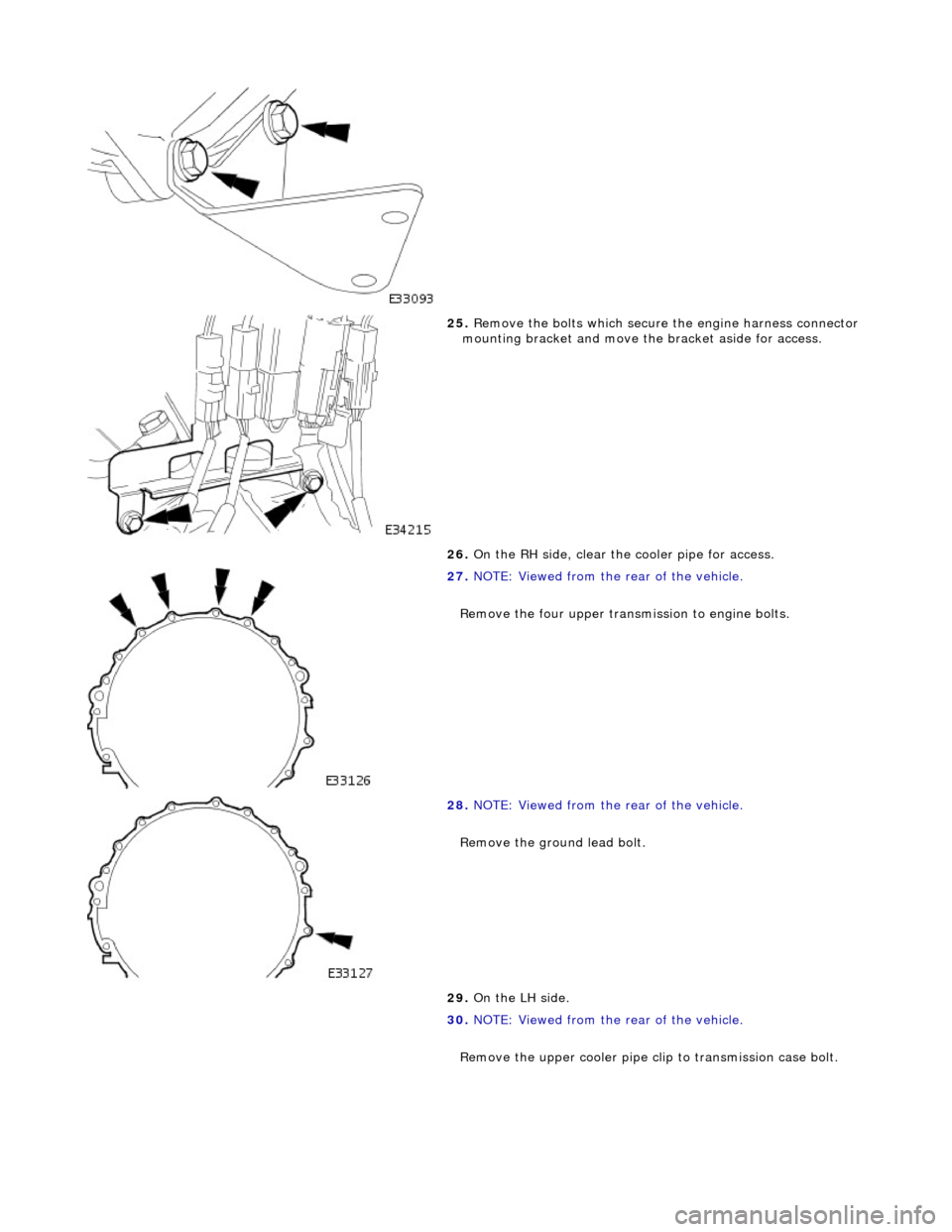
25. Remove the bolts which secure the engine harness connector
mounting bracket and move th e bracket aside for access.
26. On the RH side, clear the cooler pipe for access.
27. NOTE: Viewed from the rear of the vehicle.
Remove the four upper transmission to engine bolts.
28. NOTE: Viewed from the rear of the vehicle.
Remove the ground lead bolt.
29. On the LH side.
30. NOTE: Viewed from the rear of the vehicle.
Remove the upper cooler pipe c lip to transmission case bolt.