FRONT DOOR JAGUAR X308 1998 2.G Repair Manual
[x] Cancel search | Manufacturer: JAGUAR, Model Year: 1998, Model line: X308, Model: JAGUAR X308 1998 2.GPages: 2490, PDF Size: 69.81 MB
Page 2333 of 2490
Installation
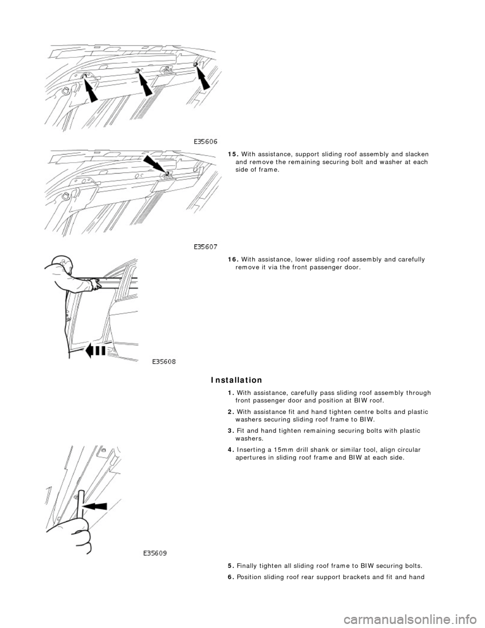
15. With assistance, support sliding roof assembly and slacken
and remove the remaining securi ng bolt and washer at each
side of frame.
16. With assistance, lower sliding roof assembly and carefully
remove it via the front passenger door.
1. With assistance, carefully pass sliding roof assembly through
front passenger door and position at BIW roof.
2. With assistance fit and hand ti ghten centre bolts and plastic
washers securing sliding roof frame to BIW.
3. Fit and hand tighten remaining securing bolts with plastic
washers.
4. Inserting a 15mm drill shank or similar tool, align circular
apertures in sliding roof fra me and BIW at each side.
5. Finally tighten all sliding roof frame to BIW securing bolts.
6. Position sliding roof rear suppo rt brackets and fit and hand
Page 2370 of 2490
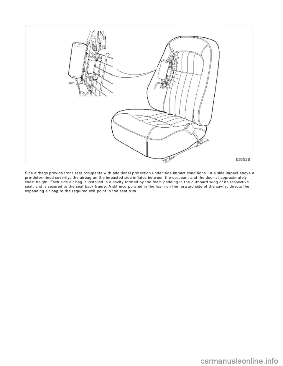
Side airbags provide front seat occupants with additional protection under side impa ct conditions. In a side impact above a
pre-determined severity, the ai rbag on the impacted side inflates between the occupant an d the door at approximately
chest height. Each side air bag is installe d in a cavity formed by the foam padding in the outboard wing of its respective
seat, and is secured to the seat back frame . A slit incorporated in the foam on the forward side of the cavity, directs the
expanding air bag to the required exit point in the seat trim.
Page 2386 of 2490
Body Structure
Introduction
The standard wheelbase Jaguar sedan has a unit construction monocoque body structure with bolt-on front fenders and
welded rear fenders. The doors feature lif t-off hinges and welded drop-glass frames.
Constructional Steel Classification
BODY ALIGNMENT
The Body Dimensions Plan, and Body Dimensions Side View, provide specified BIW dimensions to facilitate damage
assessment and location of replacemen t parts. These dimensions must be strictly applied when used for damage
assessment, component location or post repair verification.
• NOTE: The right-hand side is always looking towards the front, from the rear of the vehicle.
The nominated plan view master datums are on the right-hand side of the body with the left-hand datums dimensioned
from them. Right-hand datums must therefore be known to be correct before any other cross-car dimensions are checked.
Datum location, Example
The Front Master Datum (front crossmember rear mounting at the inner face of the main floor RH longitudinal) is nominally
359,5mm to the right-hand side of the body center line. The LH side fron t datum is measured 717,0 / 721,0mm from the
RH. Refer to the Body Dimensions Plan.
Expressed as a true posi tion in three planes, the front master datum is:
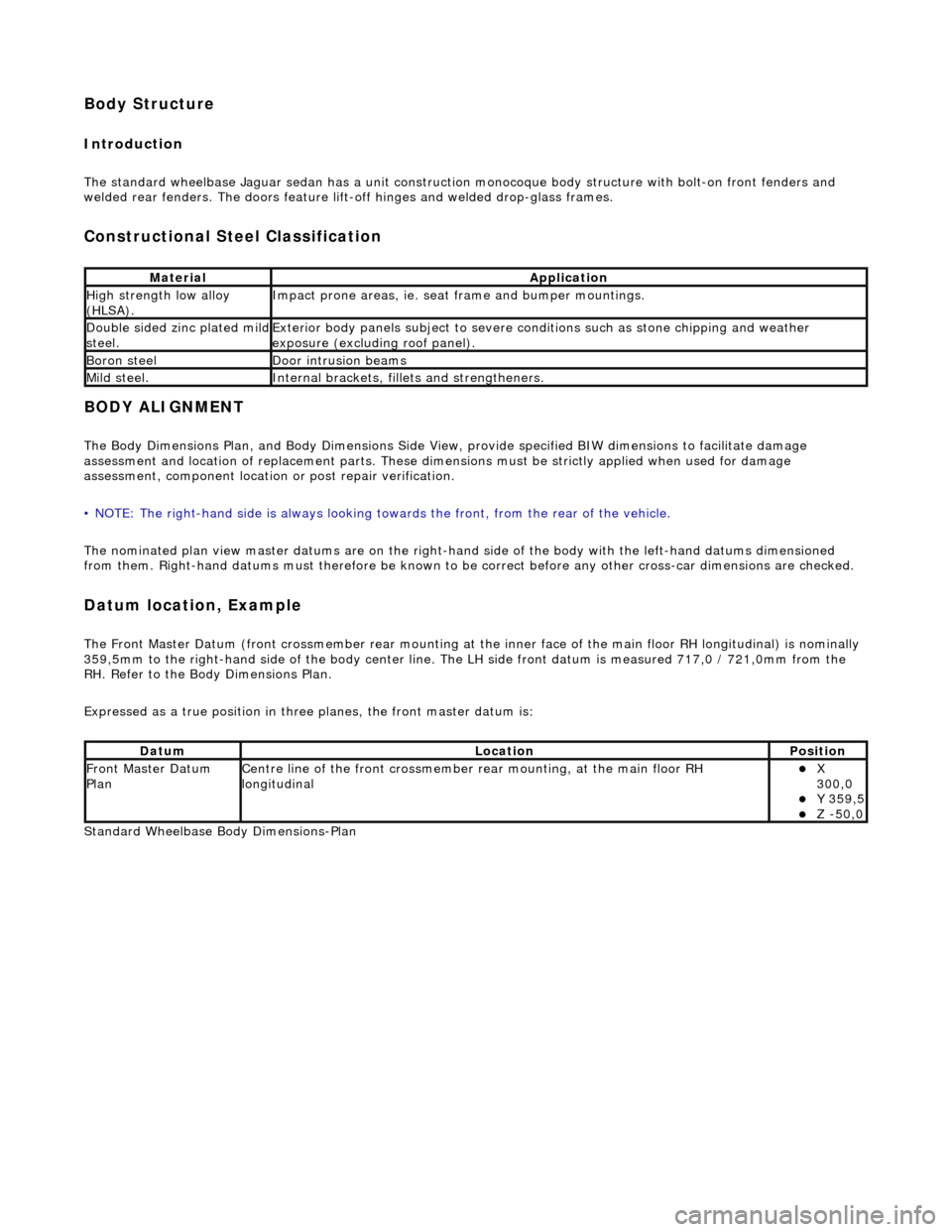
Standard Wheelbase Bo dy Dimensions-Plan
MaterialApplication
High strength low alloy
(HLSA).Impact prone areas, ie. seat frame and bumper mountings.
Double sided zinc plated mild steel.Exterior body panels subject to severe cond itions such as stone chipping and weather
exposure (excluding roof panel).
Boron steelDoor intrusion beams
Mild steel.Internal brackets, fill ets and strengtheners.
DatumLocationPosition
Front Master Datum
PlanCentre line of the front crossmember rear mounting, at the main floor RH
longitudinalX
300,0
Y 359,5 Z -50,0
Page 2408 of 2490
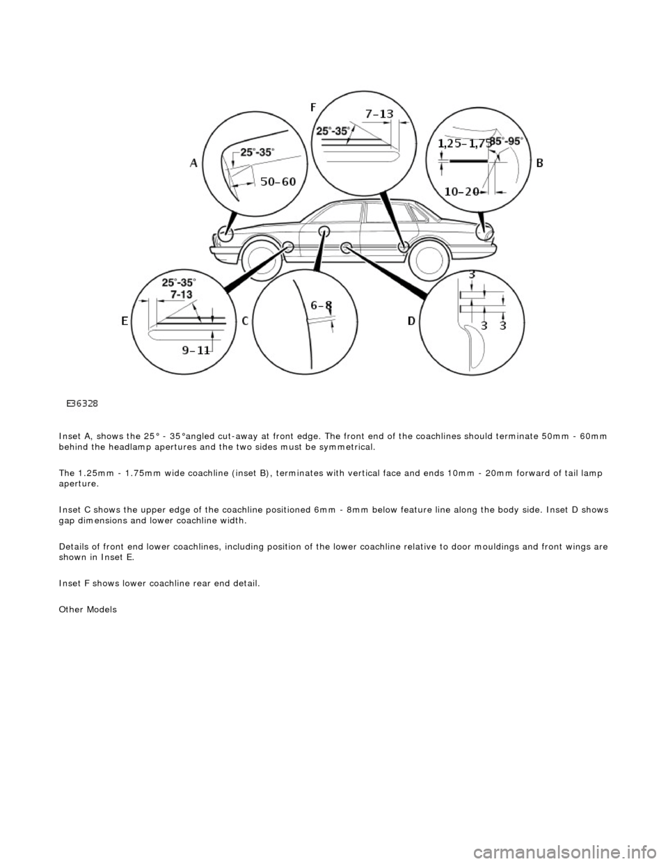
Inset A, shows the 25° - 35°angled cut-away at front edge. The front end of the coachlines should terminate 50mm - 60mm behind the headlamp apertures and the two sides must be symmetrical.
The 1.25mm - 1.75mm wide coachline (inset B), terminates with vertical face and ends 10mm - 20mm forward of tail lamp
aperture.
Inset C shows the upper edge of the coac hline positioned 6mm - 8mm below feature line along the body side. Inset D shows
gap dimensions and lower coachline width.
Details of front end lower coachlines, including position of the lower coachline relative to door mouldings and front wings are
shown in Inset E.
Inset F shows lower coachline rear end detail.
Other Models
Page 2417 of 2490
Panels centered between two adjacent panels must have equal gaps on either side. For exceptions to this, refer to the
appropriate specification. Gaps between ad jacent panels or components must not expose harnesses, labels, brackets or
visually poor joint or assembly conditions.
• NOTE: Sliding roof panel clearances are specified without the edge seal installed.
Areas of particular concern are, fuel filler flap, trunk lid to fenders and saddle panels, hood to fenders, grill and headlamps,
sliding roof to main roof panel, door gaps at fenders, B\C posts, roof drip rail an d rocker panel, and bumper cover to fenders
and cross car assemblies
Alignment
Panels must be correctly profiled to maintain cosmetic appearance, and ensure co rrect seating of seals with minimal wind
noise. Areas of particular concern are hood to fenders, trunk lid to fenders and saddle panels, doors to apertures, doors to
fenders and adjacent doors and relationship of the sliding roof panel leading and trailing edges to the main roof panel.
Exterior Fitments
Bezels, trims and lamps must be concentric with apertu res and have equal clearances with adjacent panels.
Areas of particular concern are headlamp to hood, fender and trim panel, exhaust tailpipe trim to bumper cover cut-out,
rear lamp assembly to trunk lid, fender and bumper cover trim, and side feature lines including body side mouldings, fender
to door and door to door.
Exterior Clearances and Alignments-Front