bleed JAGUAR X308 1998 2.G Repair Manual
[x] Cancel search | Manufacturer: JAGUAR, Model Year: 1998, Model line: X308, Model: JAGUAR X308 1998 2.GPages: 2490, PDF Size: 69.81 MB
Page 471 of 2490
Stee
ring System - General Informatio
n - Power Steering System Filling
and Bleeding
Gen
eral Procedures
Fluid Level Indica
tor
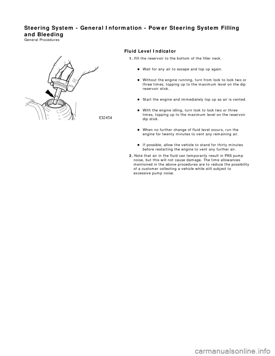
1.
F
ill the reservoir to the bo
ttom of the filler neck.
W
ait for any air to escape and top up again.
W
ithout the engine running, tu
rn from lock to lock two or
three times, topping up to the maximum level on the dip
reservoir stick.
St
art the engine and
immediately top up as air is vented.
W
ith the engine idling, turn
lock to lock two or three
times, topping up to the ma ximum level on the reservoir
dip stick.
W
hen no further change of
fluid level occurs, run the
engine for twenty minutes to vent any remaining air.
If po
ssible, allow the vehicle
to stand for thirty minutes
before restarting the engine to vent any further air.
2. Note that air in the fluid can temporarily result in PAS pump
noise, but this will not cause damage. The time allowances
mentioned in the above procedures are to reduce the possibility
of a customer collecting a vehicle while still subject to
excessive pump noise.
Page 476 of 2490

Steering System - Gen
eral Informatio
n - Power Steering System Vacuum
Filling and Bleeding
Gen e
ral Procedures
Fluid Ho
ses
1.
Parts L i
st
It
e
m
De
scr
iption
1R
e
turn hose
2High
pressure h
ose
2. If vacuum filling equipment is available, proceed as follows:
Disconnect both the
high pres
sure hose and return hose
from the PAS pump and the re turn hose from the steering
rack.
D rain as much fl
uid as possible from the system by
turning the steering from lock to lock two or three times.
Re conn
ect all hoses.
Fi
ll
the system using the vacuum equipment according to
the manufacturers instructions.
St art
the engine and top up
the fluid as necessary.
Turn the steering from lock to lock two or three ti mes wi
th
the engine running, topping up with fluid as necessary.
If possibl
e, run the engine for twenty minutes to expel any
remaining air.
Page 497 of 2490

Locate the ti
e rod end into the steering arm.
Inst
all a new nut.
Tigh
ten the nut to 22-28 Nm.
12
.
NOTE: Make sure the steering wheel and wheel and tire
assemblies are in the straight ah ead position before fitting the
steering column lower shaft.
Attach the steering column lower shaft.
1. Attach the steering column lower shaft.
2. Install the steering column lower shaft retaining bolt.
1. Tighten to 28 - 34 Nm
.
3
. Tighten to 28 - 34 Nm.
13. Fit a new power steering fluid re servoir, refill with new power
steering fluid and blee d air from the system.
For additional information, refer to: Power Steering System
Fillin
g and Bleeding
(211-00 Steering System - General
Information, Gene ral Procedures).
14. Check and adjust the front toe.
For additional information, refer to: Front Toe Adjustment
(204-00 Suspen
sion System -
General Information, General
Procedures).
Page 705 of 2490
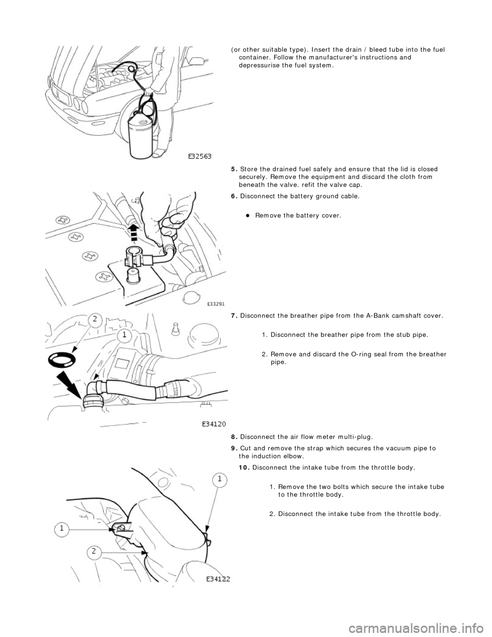
(or other sui
table type). Insert the drain / bleed tube
into the fuel
container. Follow the manufa cturer's instructions and
depressurise the fuel system.
5. Store the drained fuel safely and ensure that the lid is closed
securely. Remove the equipmen t and discard the cloth from
beneath the valve. refit the valve cap.
6. Di
sconnect the batt
ery ground cable.
R
emove the battery cover.
7. Disconnect the breather pipe fro m the
A-Bank camshaft cover.
1. Disconnect the breather pipe from the stub pipe.
2. Remove and discard the O-ring seal from the breather
pipe.
8. Disconnect the air fl ow meter multi-plug.
9. Cut and remove the strap which secures the vacuum pipe to
the induction elbow.
10
.
Disconnect the intake tube from the throttle body.
1. Remove the two bolts which secure the intake tube to the throttle body.
2. Disconnect the intake tube from the throttle body.
Page 718 of 2490
Engine - Intake Manifold Gaskets
In-vehicle Repair
Removal
WARNING: BEFORE PROCEEDING, IT IS ESSENTIAL THAT THE WARNINGS GIVEN IN SECTION 100-00 (UNDER THE
HEADING 'SAFETY PRECAUTIONS') ARE READ AND UNDERSTOOD.
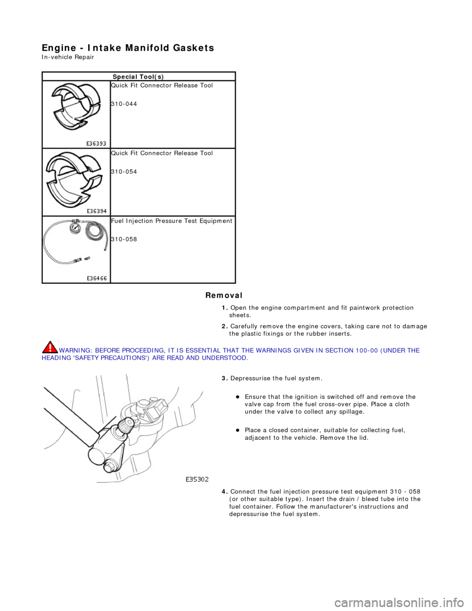
Special Tool(s)
Quick Fit Connector Release Tool
310-044
Quick Fit Connector Release Tool
310-054
Fuel Injection Pressu re Test Equipment
310-058
1. Open the engine compartment and fit paintwork protection
sheets.
2. Carefully remove the en gine covers, taking care not to damage
the plastic fixings or the rubber inserts.
3. Depressurise the fuel system.
Ensure that the ignition is switched off and remove the
valve cap from the fuel cross-over pipe. Place a cloth
under the valve to collect any spillage.
Place a closed container, su itable for collecting fuel,
adjacent to the vehicle. Remove the lid.
4. Connect the fuel injection pres sure test equipment 310 - 058
(or other suitable type). Insert the drain / bleed tube into the
fuel container. Follow the ma nufacturer's instructions and
depressurise the fuel system.
Page 729 of 2490
Engine - Intake Manifold LH
In-vehicle Repair
Removal
WARNING: BEFORE PROCEEDING, IT IS ESSENTIAL THAT THE WARNINGS GIVEN IN SECTION 100-00 (UNDER THE
HEADING 'SAFETY PRECAUTIONS') ARE READ AND UNDERSTOOD. 1.
Open the engine compartment and fit paintwork protection
sheets.
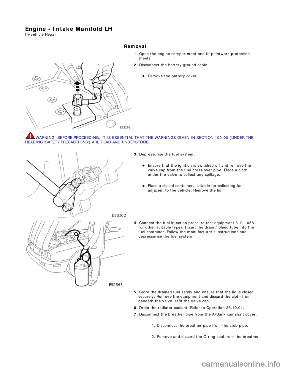
2. Disconnect the batt ery ground cable.
Remove the battery cover.
3. Depressurise the fuel system.
Ensure that the ignition is switched off and remove the
valve cap from the fuel cross-over pipe. Place a cloth
under the valve to collect any spillage.
Place a closed container, su itable for collecting fuel,
adjacent to the vehicle. Remove the lid.
4. Connect the fuel injection pres sure test equipment 310 - 058
(or other suitable type). Insert the drain / bleed tube into the
fuel container. Follow the ma nufacturer's instructions and
depressurise the fuel system.
5. Store the drained fuel safely and ensure that the lid is closed
securely. Remove the equipmen t and discard the cloth from
beneath the valve. refit the valve cap.
6. Drain the radiator coolant. Refer to Operation 26.10.01.
7. Disconnect the breather pipe fro m the A-Bank camshaft cover.
1. Disconnect the breather pipe from the stub pipe.
2. Remove and discard the O-ring seal from the breather
Page 734 of 2490
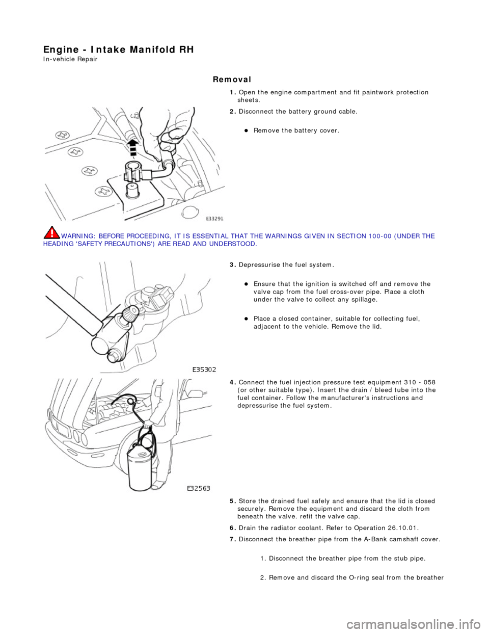
Engine - Intake Manifold RH
In-vehicle Repair
Removal
WARNING: BEFORE PROCEEDING, IT IS ESSENTIAL THAT THE WARNINGS GIVEN IN SECTION 100-00 (UNDER THE
HEADING 'SAFETY PRECAUTIONS') ARE READ AND UNDERSTOOD. 1.
Open the engine compartment and fit paintwork protection
sheets.
2. Disconnect the batt ery ground cable.
Remove the battery cover.
3. Depressurise the fuel system.
Ensure that the ignition is switched off and remove the
valve cap from the fuel cross-over pipe. Place a cloth
under the valve to collect any spillage.
Place a closed container, su itable for collecting fuel,
adjacent to the vehicle. Remove the lid.
4. Connect the fuel injection pres sure test equipment 310 - 058
(or other suitable type). Insert the drain / bleed tube into the
fuel container. Follow the ma nufacturer's instructions and
depressurise the fuel system.
5. Store the drained fuel safely and ensure that the lid is closed
securely. Remove the equipmen t and discard the cloth from
beneath the valve. refit the valve cap.
6. Drain the radiator coolant. Refer to Operation 26.10.01.
7. Disconnect the breather pipe fro m the A-Bank camshaft cover.
1. Disconnect the breather pipe from the stub pipe.
2. Remove and discard the O-ring seal from the breather
Page 739 of 2490
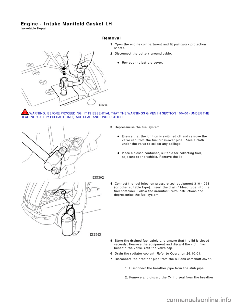
Engine - Intake Manifold Gasket LH
In-vehicle Repair
Removal
WARNING: BEFORE PROCEEDING, IT IS ESSENTIAL THAT THE WARNINGS GIVEN IN SECTION 100-00 (UNDER THE
HEADING 'SAFETY PRECAUTIONS') ARE READ AND UNDERSTOOD. 1.
Open the engine compartment and fit paintwork protection
sheets.
2. Disconnect the batt ery ground cable.
Remove the battery cover.
3. Depressurise the fuel system.
Ensure that the ignition is switched off and remove the
valve cap from the fuel cross-over pipe. Place a cloth
under the valve to collect any spillage.
Place a closed container, su itable for collecting fuel,
adjacent to the vehicle. Remove the lid.
4. Connect the fuel injection pres sure test equipment 310 - 058
(or other suitable type). Insert the drain / bleed tube into the
fuel container. Follow the ma nufacturer's instructions and
depressurise the fuel system.
5. Store the drained fuel safely and ensure that the lid is closed
securely. Remove the equipmen t and discard the cloth from
beneath the valve. refit the valve cap.
6. Drain the radiator coolant. Refer to Operation 26.10.01.
7. Disconnect the breather pipe fro m the A-Bank camshaft cover.
1. Disconnect the breather pipe from the stub pipe.
2. Remove and discard the O-ring seal from the breather
Page 744 of 2490
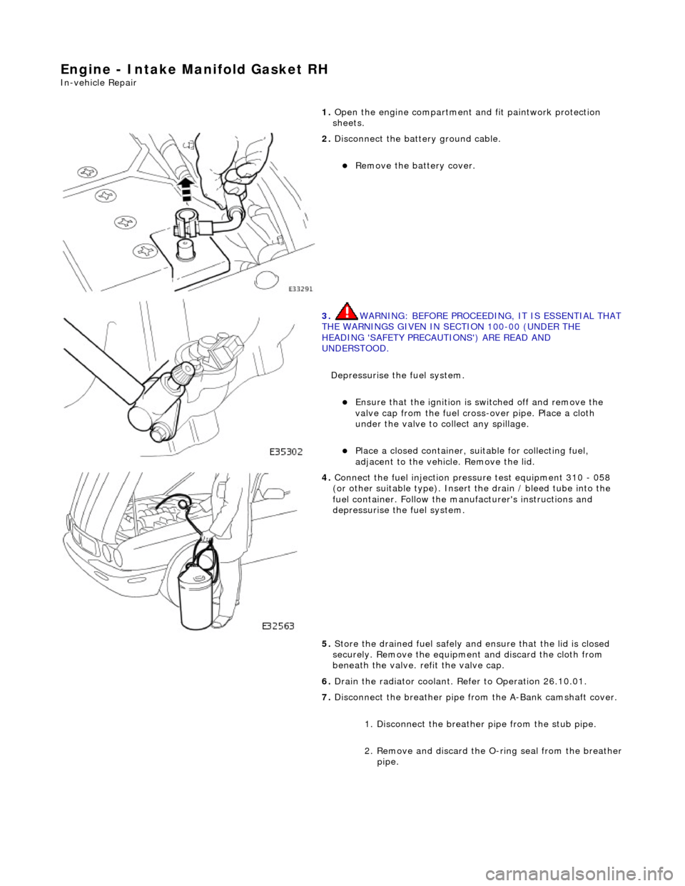
Engine - Intake Manifold Gasket RH
In-vehicle Repair
1. Open the engine compartment and fit paintwork protection
sheets.
2. Disconnect the batt ery ground cable.
Remove the battery cover.
3. WARNING: BEFORE PROCEEDING, IT IS ESSENTIAL THAT THE WARNINGS GIVEN IN SECTION 100-00 (UNDER THE
HEADING 'SAFETY PRECAUTIONS') ARE READ AND
UNDERSTOOD.
Depressurise the fuel system.
Ensure that the ignition is switched off and remove the
valve cap from the fuel cross-over pipe. Place a cloth
under the valve to collect any spillage.
Place a closed container, su itable for collecting fuel,
adjacent to the vehicle. Remove the lid.
4. Connect the fuel injection pres sure test equipment 310 - 058
(or other suitable type). Insert the drain / bleed tube into the
fuel container. Follow the ma nufacturer's instructions and
depressurise the fuel system.
5. Store the drained fuel safely and ensure that the lid is closed
securely. Remove the equipmen t and discard the cloth from
beneath the valve. refit the valve cap.
6. Drain the radiator coolant. Refer to Operation 26.10.01.
7. Disconnect the breather pipe fro m the A-Bank camshaft cover.
1. Disconnect the breather pipe from the stub pipe.
2. Remove and discard the O-ring seal from the breather
pipe.
Page 898 of 2490
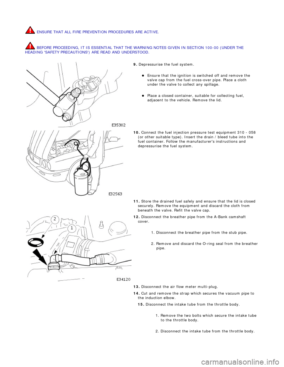
ENSURE THAT ALL FIRE PREVENTION PROCEDURES ARE ACTIVE.
BEFORE PROCEEDING, IT IS ESSENTIAL THAT THE WARNING NOTES GIVEN IN SECTION 100-00 (UNDER THE
HEADING 'SAFETY PRECAUTIONS') ARE READ AND UNDERSTOOD.
9. Depressurise the fuel system.
Ensure that the ignition is switched off and remove the
valve cap from the fuel cross-over pipe. Place a cloth
under the valve to collect any spillage.
Place a closed container, su itable for collecting fuel,
adjacent to the vehicle. Remove the lid.
10. Connect the fuel injection pressure test equipment 310 - 058
(or other suitable type). Insert the drain / bleed tube into the
fuel container. Follow the ma nufacturer's instructions and
depressurise the fuel system.
11. Store the drained fuel safely and ensure that the lid is closed
securely. Remove the equipmen t and discard the cloth from
beneath the valve. Refit the valve cap.
12. Disconnect the breather pipe from the A-Bank camshaft
cover.
1. Disconnect the breather pipe from the stub pipe.
2. Remove and discard the O-ring seal from the breather
pipe.
13. Disconnect the air flow meter multi-plug.
14. Cut and remove the strap which secures the vacuum pipe to
the induction elbow.
15. Disconnect the intake tube from the throttle body.
1. Remove the two bolts which secure the intake tube to the throttle body.
2. Disconnect the intake tube from the throttle body.