bleed JAGUAR X308 1998 2.G Owner's Guide
[x] Cancel search | Manufacturer: JAGUAR, Model Year: 1998, Model line: X308, Model: JAGUAR X308 1998 2.GPages: 2490, PDF Size: 69.81 MB
Page 375 of 2490
i
nstalled to prevent it fouling on the steering and suspension
components.
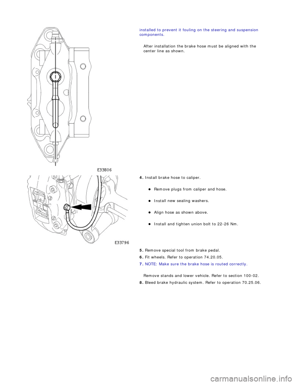
After installation the brake ho se must be aligned with the
center line as shown.
4. Install brake hose to
caliper.
Remove plugs f
rom caliper and hose.
Inst
all new sealing washers.
Align hos
e as shown above.
Install and tigh
ten union bolt to 22-26 Nm.
5. Remove special tool from brake pedal.
6. Fit wheels. Refer to operation 74.20.05.
7. NOTE: Make sure the brake hose is routed correctly.
Remove stands and lower vehicl e. Refer to section 100-02.
8. Bleed brake hydraulic system. Refer to operation 70.25.06.
Page 405 of 2490

Hydraulic B
rake Actuation -
Lubri
cants, Fluids, Sealants and Adhesives
Torques
Torques - Brembo Brakes
Brake Tube, Hoses and Bracket Torques
CAUTI
ON: Replacement of
nuts and bolts: Various thread-locking devices are used on nuts and bolts throughout the
vehicle. These devices restrict the number of times a nut or bolt can be used. See section 100-00 for information.
UnitS
pecification
Brake flu
id
ITT Supe
r Dot 4
Com
ponent
Nm
N
ut - master cylinder to brake booster
21
-29
Nu
t - brake pedal pivot-pin to pedal housing
17
-23
Nu
t - brake switch to pedal housing
3
Nu
t - pedal housing to body
15
-20
Nu
t - brake booster to pedal housing
22
-28
Com
ponent
Nm
Bleed n
ipple
12
-16
U
nion bolt - brake hose to caliper
22
-26
Com
ponent
Nm
Bleed n
ipple - front
4-
6
Bleed n
ipple - rear
8-1
1
Hose to fr
ont caliper
10
-14
U
nion to rear caliper - union bolt
30
-40
M1
0 hose locknut
15
-20
M10
brake tube female-nut
13
-17
M10
brake tube male-nut
13
-17
M12
brake tube male-nut
15
-20
M18
brake tube male-nut
22
-28
Brake tube clip retention
-bracket to body
4-
6
Page 410 of 2490

8
6
.15.15 for further information).
6. Bleed brake system. Refer to operation 70.25.03.
7. Remove paint-work protection covers and close engine
compartment.
Page 413 of 2490

Lubricate seals with cl
ean brake fluid.
Inst
all seals.
2. Install
fluid reservoir to master cylinder.
R
emove plugs from reservoir
Install
reservoir, making sure
reservoir is fully seated.
Inst
all locating pin.
3. Inst
all master cylinder to brake booster.
Inst
all seal.
Inst
all master cylinder, make sure master cylinder rod
locates brake booster rod.
4. Inst
all and tighten nuts to 21-29 Nm.
5. Install pedal housing, brake booster and master cylinder
assembly. Refer to operation 70.35.39.
6. Install engine compartment rear cover. Refer to operation
76.11.35.
7. Connect battery ground cable (IMPORTANT, see operation
86.15.15 for further information).
8. Bleed brake system. Refer to operation 70.25.03.
9. Remove paint-work protection covers and close engine
com
partment.
Page 415 of 2490
2
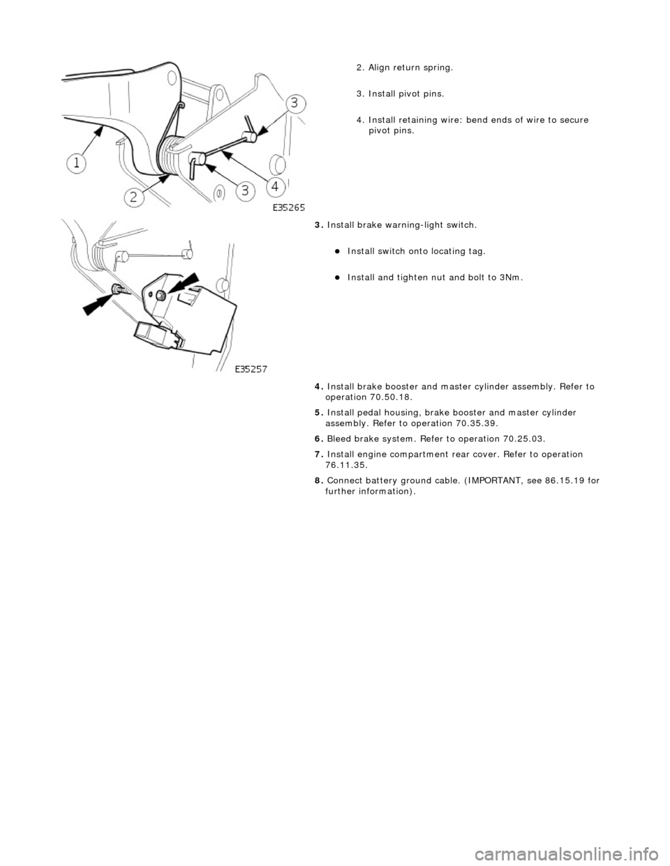
. Align return spring.
3. Install pivot pins.
4. Install retaining wire: bend ends of wire to secure
pivot pins.
3. Inst
all brake warning-light switch.
Inst
all switch onto locating tag.
Install and tigh
ten nut and bolt to 3Nm.
4. Install brake booster and master cylinder assembly. Refer to
operation 70.50.18.
5. Install pedal housing, brake booster and master cylinder
assembly. Refer to operation 70.35.39.
6. Bleed brake system. Refer to operation 70.25.03.
7. Install engine compartment rear cover. Refer to operation
76.11.35.
8. Connect battery ground cable. (IMPORTANT, see 86.15.19 for
further information).
Page 420 of 2490
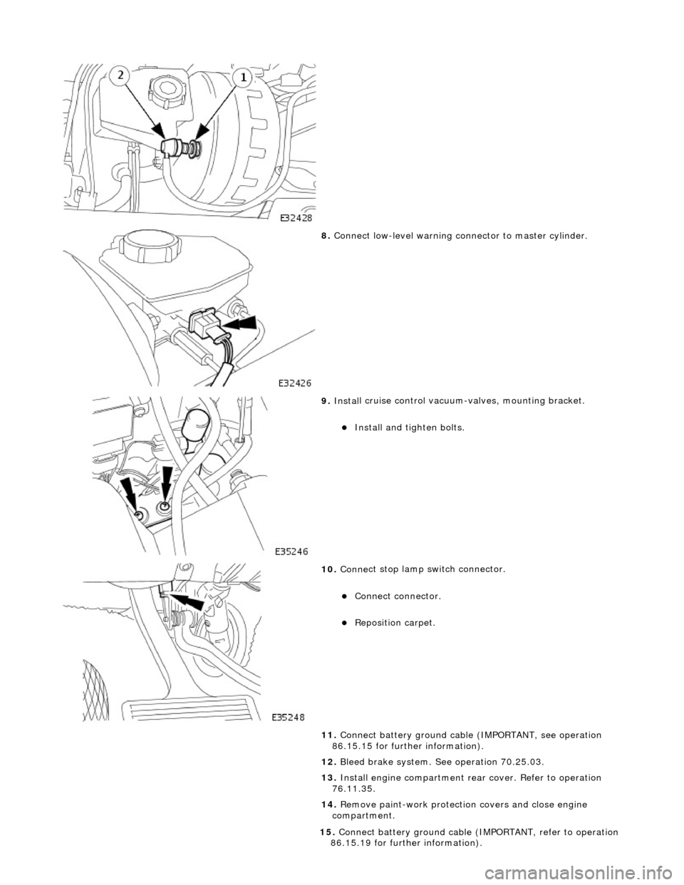
8. Conne ct
low-level warning connector to master cylinder.
9. Inst al
l cruise control vacuum-valves, mounting bracket.
Install and tigh
ten bolts.
10 . Conne
ct stop lamp switch connector.
Conne
ct
connector.
Re
posi
tion carpet.
11. Connect battery ground cable (IMPORTANT, see operation
86.15.15 for further information).
12. Bleed brake system. See operation 70.25.03.
13. Install engine compartment rear cover. Refer to operation
76.11.35.
14. Remove paint-work protection covers and close engine
compartment.
15 . Conne
ct battery ground cable (I
MPORTANT, refer to operation
86.15.19 for further information).
Page 421 of 2490
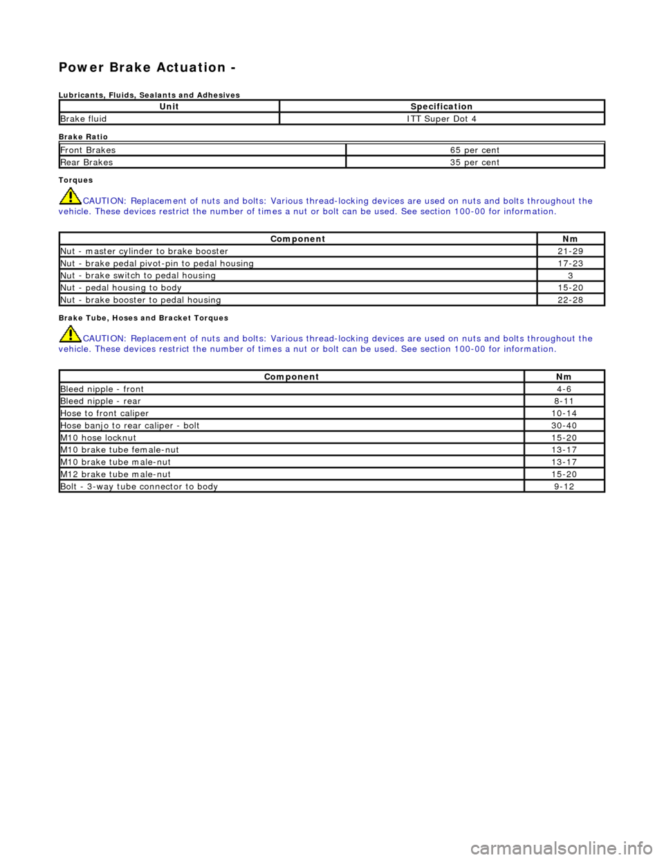
Power Brake Actuation -
Lubri
cants, Fluids, Sealants and Adhesives
Brake Ratio
Torques
CAUTI
ON: Replacement of
nuts and bolts: Various thread-locking devices are used on nuts and bolts throughout the
vehicle. These devices restrict the number of times a nut or bolt can be used. See section 100-00 for information.
B
rake Tube, Hoses and Bracket Torques
CAUTI
ON: Replacement of
nuts and bolts: Various thread-locking devices are used on nuts and bolts throughout the
vehicle. These devices restrict the number of times a nut or bolt can be used. See section 100-00 for information.
UnitS
pecification
Brake flu
id
ITT Supe
r Dot 4
Fr
ont Brakes
6
5 per cent
Rear B
rakes
3
5 per cent
Com
ponent
Nm
N
ut - master cylinder to brake booster
21
-29
Nu
t - brake pedal pivot-pin to pedal housing
17
-23
Nu
t - brake switch to pedal housing
3
Nu
t - pedal housing to body
15
-20
Nu
t - brake booster to pedal housing
22
-28
Com
ponent
Nm
Bleed n
ipple - front
4-
6
Bleed n
ipple - rear
8-
11
Hose to fr
ont caliper
10
-14
Hose banjo to rear caliper -
bolt
30
-40
M1
0 hose locknut
15
-20
M10
brake tube female-nut
13
-17
M10
brake tube male-nut
13
-17
M12
brake tube male-nut
15
-20
Bolt -
3-way tube connector to body
9-
12
Page 424 of 2490
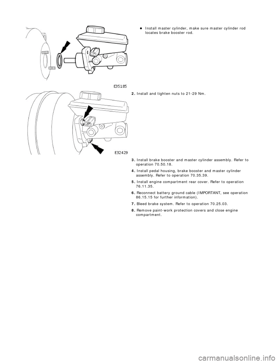
Instal
l master cylinder, make sure master cylinder rod
locates brake booster rod.
2. Inst al
l and tighten nuts to 21-29 Nm.
3. Install brake booster and master cylinder assembly. Refer to
operation 70.50.18.
4. Install pedal housing, brake booster and master cylinder
assembly. Refer to operation 70.35.39.
5. Install engine compartment rear cover. Refer to operation
76.11.35.
6. Reconnect battery ground cable (IMPORTANT, see operation
86.15.15 for further information).
7. Bleed brake system. Refer to operation 70.25.03.
8. Remove paint-work protection covers and close engine
compartment.
Page 428 of 2490
9.
Reconn
ect battery ground cable (IMPORTANT, see operation
86.15.15 for further information).
10. Bleed brake system. Refer to operation 70.25.03.
11. Remove paint-work protection covers and close engine
compartment.
Page 429 of 2490
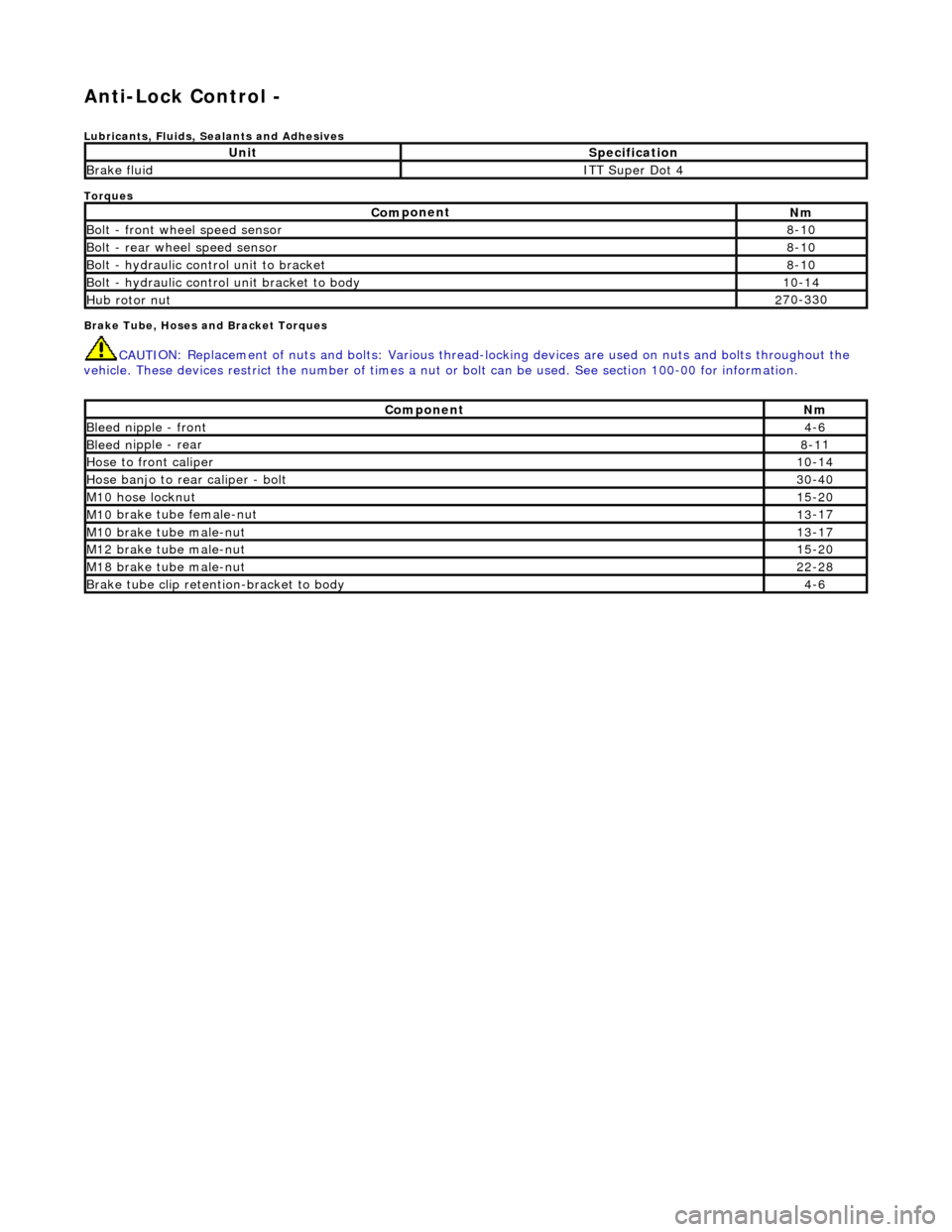
Anti-Lock Control -
Lubri
cants, Fluids, Sealants and Adhesives
Torques
Brake Tube, Hoses and Bracket Torques
CAUTI
ON: Replacement of
nuts and bolts: Various thread-locking devices are used on nuts and bolts throughout the
vehicle. These devices restrict the number of times a nut or bolt can be used. See section 100-00 for information.
UnitS
pecification
Brake flu
id
ITT Supe
r Dot 4
Com
ponent
Nm
Bol
t - front wheel speed sensor
8-
10
Bolt
- rear wheel speed sensor
8-
10
Bo
lt - hydraulic control unit to bracket
8-
10
Bolt -
hydraulic control unit bracket to body
10
-14
Hub rotor nut2
70-330
Com
ponent
Nm
Bleed n
ipple - front
4-
6
Bleed n
ipple - rear
8-1
1
Hose to fr
ont caliper
10
-14
Hose banjo to rear caliper -
bolt
30
-40
M1
0 hose locknut
15
-20
M10
brake tube female-nut
13
-17
M10
brake tube male-nut
13
-17
M12
brake tube male-nut
15
-20
M18
brake tube male-nut
22
-28
Brake tube clip retention
-bracket to body
4-
6