bleed JAGUAR X308 1998 2.G Manual Online
[x] Cancel search | Manufacturer: JAGUAR, Model Year: 1998, Model line: X308, Model: JAGUAR X308 1998 2.GPages: 2490, PDF Size: 69.81 MB
Page 1785 of 2490

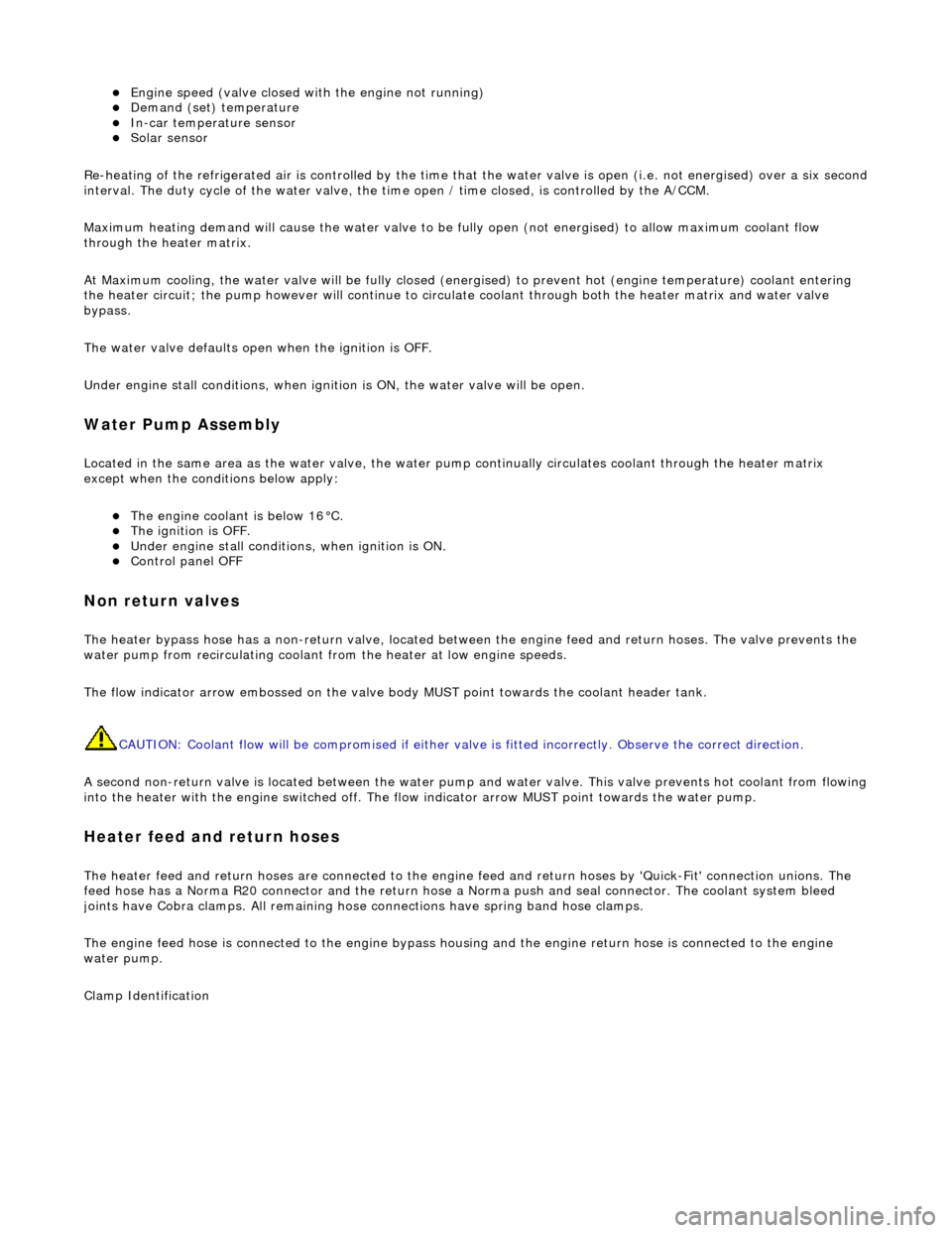
Engine speed (valve closed with the engine not running) Demand (set) temperature In-car temperature sensor Solar sensor
Re-heating of the refrigerated air is contro lled by the time that the water valve is open (i.e. not energised) over a six secon d
interval. The duty cycle of the water valve, the time open / time closed, is controlled by the A/CCM.
Maximum heating demand will cause the water valve to be fu lly open (not energised) to allow maximum coolant flow
through the heater matrix.
At Maximum cooling, the water va lve will be fully closed (energised) to prevent hot (engine temperature) coolant entering
the heater circuit; the pump however will continue to circulate coolant through both the heater matrix and water valve
bypass.
The water valve defaults open when the ignition is OFF.
Under engine stall conditions, when ignition is ON, the water valve will be open.
Water Pump Assembly
Located in the same area as the water valve, the water pump continually circulates coolant through the heater matrix
except when the conditions below apply:
The engine coolant is below 16°C. The ignition is OFF. Under engine stall conditions, when ignition is ON. Control panel OFF
Non return valves
The heater bypass hose has a non-return valve, located between the engine feed and return hoses. The valve prevents the
water pump from recirculating coolant fro m the heater at low engine speeds.
The flow indicator arrow embossed on the valve bo dy MUST point towards the coolant header tank.
CAUTION: Coolant flow will be compromi sed if either valve is fitted incorrectly. Observe the correct direction.
A second non-return valve is located betw een the water pump and water valve. This valve prevents hot coolant from flowing
into the heater with the engine switched off. The flow indicator arrow MUST point towards the water pump.
Heater feed and return hoses
The heater feed and return hoses are connected to the engine feed and return hoses by 'Quick-Fit' connection unions. The
feed hose has a Norma R20 connector and the return hose a Norma push and seal connector. The coolant system bleed
joints have Cobra clamps. All remaining hose connections have spring band hose clamps.
The engine feed hose is connected to the engine bypass hous ing and the engine return hose is connected to the engine
water pump.
Clamp Identification
Page 1807 of 2490

8. Install front end accessory drive belt; refer to 12.10.40 or (SC)
12.10.40.
9. Install supercharger drive belt (where fitted); refer to
18.50.08.
10. Reconnect battery ground cable (IMPORTANT, see SRO
86.15.15 for further information).
11. Recharge air conditioning system; refer to 82.30.30.
12. Check / bleed / top up power stee ring fluid reservoir; refer to
211-02.
Page 1808 of 2490

Air Conditioning - Condenser Core
Removal and Installation
Removal
1. Disconnect battery ground cable (IMPORTANT, see SRO
86.15.19 for further information).
2. Drain radiator coolant only; refer to 26.10.01 or (SC)
26.10.01.
3. Recover refrigerant from air co nditioning system; refer to
82.30.30.
4. Release both gas struts, set the engine cover fully forward to
the service access position an d support with a wooden (or
similar) strut.
5. CAUTION: Take care not to damage hood or radiator
grille.
Remove twin fan and motor as sembly; refer to 26.25.12.
6. Disconnect radiator bleed hose.
Release connection.
7. Remove retaining clip which secures transmission oil cooler
upper and lower pipes.
8. Disconnect transmission oil cooler lower pipe from radiator.
1. Release union nut and disconne ct pipe.
Discard O-ring seal.
2. Install suitable blanking plugs.
9. From above the vehicle, discon nect transmission oil cooler
upper pipe from radiator.
1. Release union nut and disconne ct pipe.
Discard O-ring seal.
2. Install suitable blanking plugs.
Page 1825 of 2490

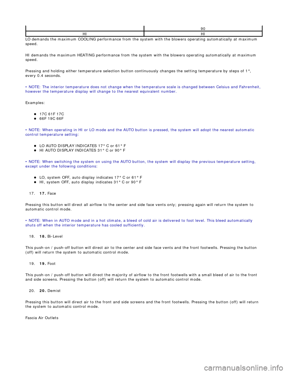
LO demands the maximum COOLING performance from the system with the blowers operating automatically at maximum
speed.
HI demands the maximum HEATING performance from the system with the blowers operating automatically at maximum
speed.
Pressing and holding either temperature selection button co ntinuously changes the setting temperature by steps of 1°,
every 0.4 seconds.
• NOTE: The interior temperature does not change when the temperature scale is changed between Celsius and Fahrenheit,
however the temperature display will chan ge to the nearest equivalent number.
Examples:
17C 61F 17C 66F 19C 66F
• NOTE: When operating in HI or LO mode and the AUTO butt on is pressed, the system will adopt the nearest automatic
control temperature setting:
LO AUTO DISPLAY INDICATES 17° C or 61° F HI AUTO DISPLAY INDICATES 31° C or 90° F
• NOTE: When switching the system on us ing the AUTO button, the system will display the previous temperature setting,
except under the following conditions:
LO, system OFF, auto display indicates 17° C or 61° F HI, system OFF, auto display indicates 31° C or 90° F
17. 17. Face
Pressing this button will direct all airflow to the center and side face vents only; pressing again will return the system to
automatic control mode.
• NOTE: When in AUTO mode and in a hot c limate, a bleed of cold air is delivered to foot level. This bleed automatically
shuts off when the inte rior temperature has cooled sufficiently.
18. 18. Bi-Level
This push-on / push-off button will direct air to the center and side face vent s and the front footwells. Pressing the button
(off) will return the system to automatic control mode.
19. 19. Foot
This push-on / push-off button will direct the majority of airflow to the front footwells with a small bleed of air to the fron t
and side screens. Pressing the button (off) will return the system to automatic control mode.
20. 20. Demist
Pressing this button will direct air to the front and side screens and the front foot wells. Pressing the button (off) will return
the system to automatic control mode.
Fascia Air Outlets
90
HIHI
Page 1838 of 2490

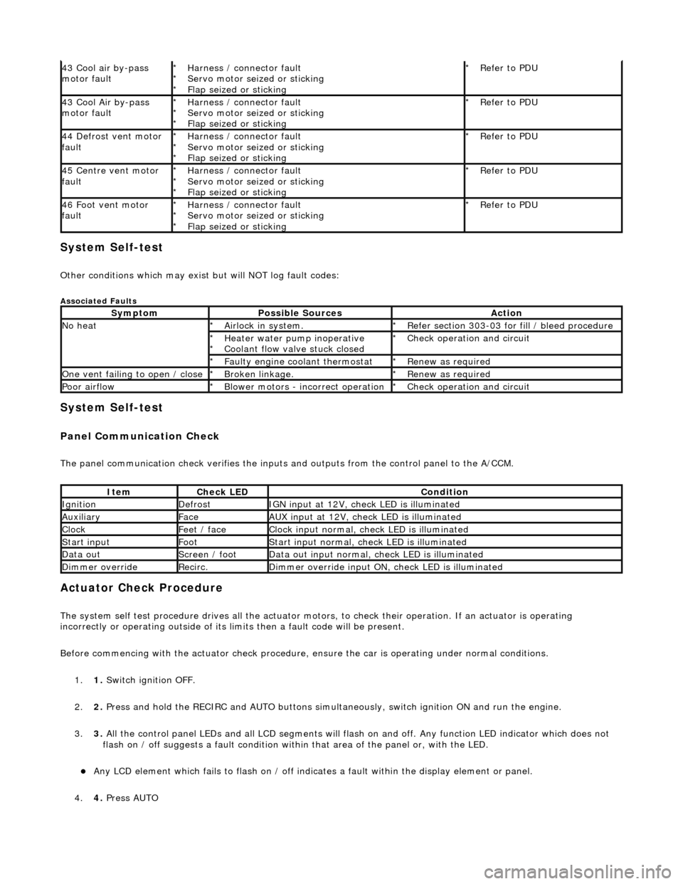
System Self-test
Other conditions which may exist but will NOT log fault codes:
Associated Faults
System Self-test
Panel Communication Check
The panel communication check veri fies the inputs and outputs from the control panel to the A/CCM.
Actuator Check Procedure
The system self test procedure drives all the actuator moto rs, to check their operation. If an actuator is operating
incorrectly or operating outside of its limi ts then a fault code will be present.
Before commencing with the actuator check procedure, ensure the ca r is operating under normal conditions.
1. 1. Switch ignition OFF.
2. 2. Press and hold the RECIRC and AUTO buttons simult aneously, switch ignition ON and run the engine.
3. 3. All the control panel LEDs and all LCD segments will flas h on and off. Any function LED indicator which does not
flash on / off suggests a fault condition within that area of the panel or, with the LED.
Any LCD element which fails to flash on / off indicates a fault within the display element or panel.
4. 4. Press AUTO
43 Cool air by-pass
motor faultHarness / connector fault
Servo motor seized or sticking
Flap seized or sticking
*
*
*Refer to PDU
*
43 Cool Air by-pass
motor faultHarness / connector fault
Servo motor seized or sticking
Flap seized or sticking
*
*
*Refer to PDU
*
44 Defrost vent motor
faultHarness / connector fault
Servo motor seized or sticking
Flap seized or sticking
*
*
*Refer to PDU
*
45 Centre vent motor
faultHarness / connector fault
Servo motor seized or sticking
Flap seized or sticking
*
*
*Refer to PDU
*
46 Foot vent motor
faultHarness / connector fault
Servo motor seized or sticking
Flap seized or sticking
*
*
*Refer to PDU
*
SymptomPossible SourcesAction
No heatAirlock in system.
*Refer section 303-03 for fill / bleed procedure
*
Heater water pump inoperative
Coolant flow valve stuck closed
*
*Check operation and circuit
*
Faulty engine coolant thermostat
*Renew as required
*
One vent failing to open / closeBroken linkage.
*Renew as required
*
Poor airflowBlower motors - incorrect operation
*Check operation and circuit
*
ItemCheck LEDCondition
IgnitionDefrostIGN input at 12V, check LED is illuminated
AuxiliaryFaceAUX input at 12V, check LED is illuminated
ClockFeet / faceClock input normal, check LED is illuminated
Start inputFootStart input normal, check LED is illuminated
Data outScreen / footData out input normal, check LED is illuminated
Dimmer overrideRecirc.Dimmer override input ON, check LED is illuminated
Page 1839 of 2490

5.5. Press RECIRC button to instigate actuator check mode.
6. 6. Press FACE to cycle through the actu ator mode conditions 20 to 27.
7. 7. Press the FAN button to restore normal operation with default panel settings, ie AUTO @ 24°C.
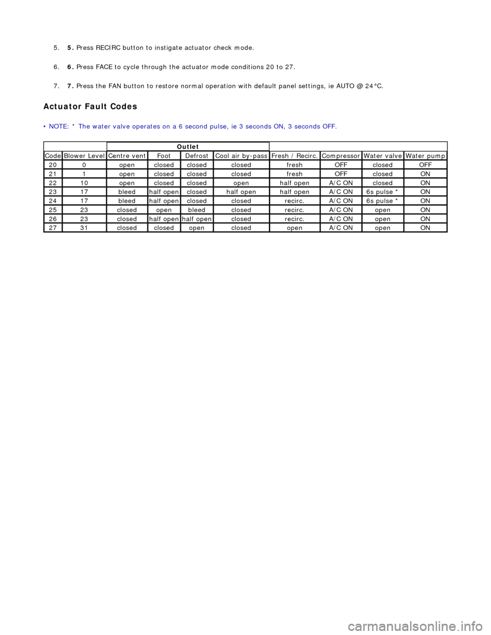
Actuator Fault Codes
• NOTE: * The water valve operates on a 6 second pulse, ie 3 seconds ON, 3 seconds OFF.
Outlet
Code Blower Level Centre vent Foot Defrost Cool air by-pass Fresh / Recirc. Compressor Water valve Water pump
200openclosedclosedclosedfreshOFFclosedOFF
211openclosedclosedclosedfreshOFFclosedON
2210openclosedclosedopenhalf openA/C ONclosedON
2317bleedhalf openclosedhalf openhalf openA/C ON6s pulse * ON
2417bleedhalf openclosedclosedrecirc.A/C ON6s pulse * ON
2523closedopenbleedclosedrecirc.A/C ONopenON
2623closedhalf openhalf openclosedrecirc.A/C ONopenON
2731closedclosedopenclosedopenA/C ONopenON