fuse JAGUAR X308 1998 2.G Repair Manual
[x] Cancel search | Manufacturer: JAGUAR, Model Year: 1998, Model line: X308, Model: JAGUAR X308 1998 2.GPages: 2490, PDF Size: 69.81 MB
Page 1723 of 2490
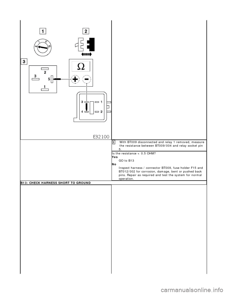
Wi
th BT009 disconnected an
d relay 1 removed, measure
the resistance between BT009/004 and relay socket pin
5.
1
I
s the resistance < 0.5 OHM?
Yes GO to B13
No Inspect harness / connector BT 009, fuse holder F15 and
BT012/002 for corrosion, damage, bent or pushed back
pins. Repair as required and test the system for normal
operation.
B13: CHECK HARNESS SHO
RT TO GROUND
Page 1859 of 2490
Horn - Horn
Description and Operation
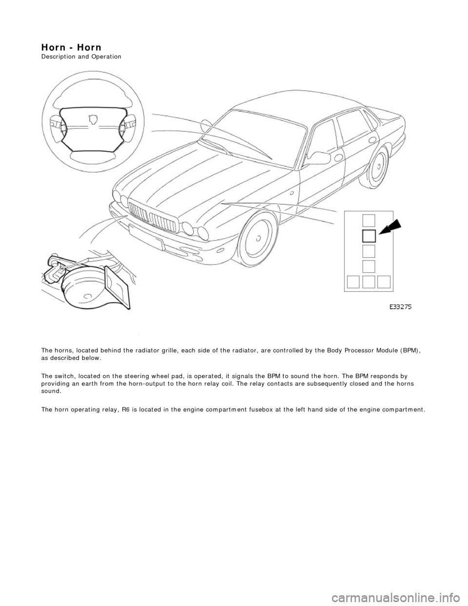
The horns, located behind the radiator gril le, each side of the radiator, are controlled by the Body Processor Module (BPM),
as described below.
The switch, located on the steering wheel pad, is operated, it signals the BPM to sound the horn. The BPM responds by
providing an earth from the horn-output to the horn relay coil. The relay contacts are subsequently closed and the horns
sound.
The horn operating relay, R6 is located in the engine compartm ent fusebox at the left hand side of the engine compartment.
Page 1861 of 2490
Clock - Clock
Description and Operation
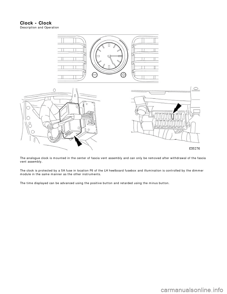
The analogue clock is mounted in the center of fascia vent assembly and can only be removed after withdrawal of the fascia
vent assembly.
The clock is protected by a 5A fuse in lo cation F6 of the LH heelboard fusebox and illumination is controlled by the dimmer
module in the same manner as the other instruments.
The time displayed can be advanced using the positive button and retarded using the minus button.
Page 1870 of 2490
Parking Aid - Parking Aid
Diagnosis and Testing
Inspection and Verification
1.1. Verify the customer concern.
2. 2. Visually inspect for obvious signs of mechanical or electrical damage.
Visual Inspection Chart
3. 3. If an obvious cause for an observed or reported concern is found, correct the cause (if possible) before proceeding to the next step
4. 4. If the cause is not visually evident, verify the sympto m and refer to the Jaguar approved diagnostic system.
Electrical
Fuse(s) Relay(s) Wiring Harness Electrical connector(s) Rear parking aid sensor(s) Rear parking aid speaker Reversing lamp switch Parking aid module
Page 1876 of 2490
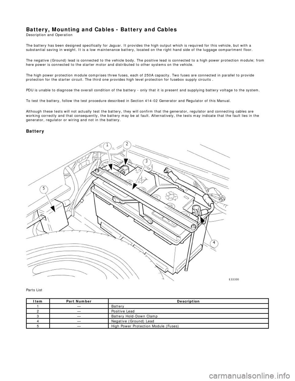
Battery, Mounting and Cables - Battery and Cables Description and Operation
The battery has been designed specifically for Jaguar. It provides the high output which is required for this vehicle, but with a
substantial saving in weight. It is a low maintenance battery, located on the right ha nd side of the luggage compartment floor.
The negative (Ground) lead is connected to the vehicle body. The positive lead is connected to a high power protection module; from
here power is connected to the starter motor an d distributed to other systems on the vehicle.
The high power protection module comprises three fuses, each of 250A capacity. Two fuses are connected in parallel to provide
protection for the starter circuit. Th e third one provides high level protection for fusebox supply circuits .
PDU is unable to diagnose the overall condition of the battery - only that it is present and supplying battery voltage to the system.
To test the battery, follow the test procedure described in Section 414-02 Generator and Regulator of this Manual.
Although these tests will not actually test the battery, they will confirm that the generator, regulator and connecting cables are
working correctly and that conseq uently, the battery may be at fault. Alternatively, the tests may indicate that the fault lies in the
generator, regulator or wiring and not in the battery.
Battery
Parts List
ItemPart NumberDescription
1—Battery
2—Positive Lead
3—Battery Hold-Down Clamp
4—Negative (Ground) Lead
5—High Power Protection Module (Fuses)
Page 1883 of 2490
Belt tension is achieved by an automatic tensioner; neither the belt nor the tensioner require service apart from checking
the belt wear indicators at each normal service interval.
The minimum service life of the drive belt is 100,000 miles.
Never apply oil to the belt or to the belt tensioner.
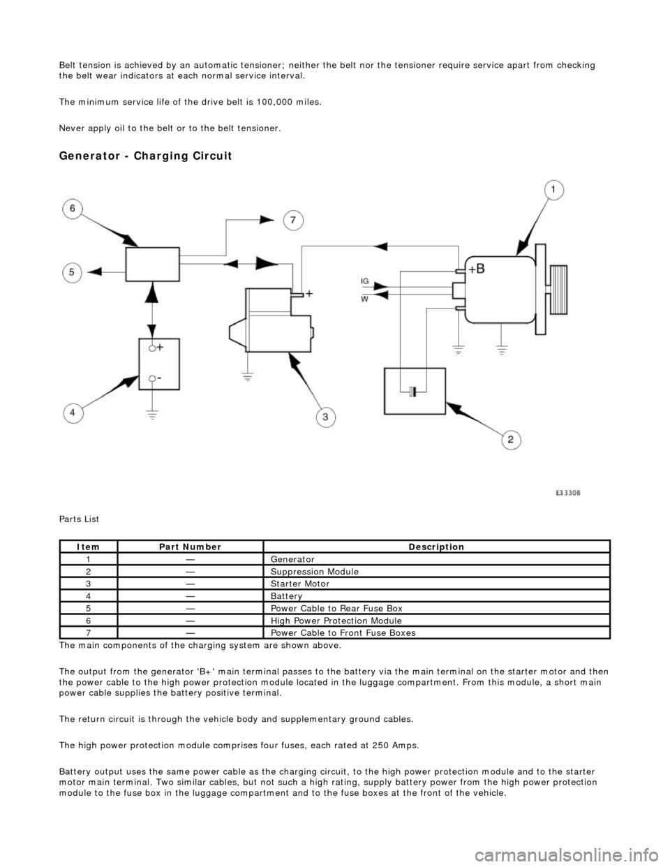
Generator - Charging Circuit
Parts List
The main components of the charging system are shown above.
The output from the generator 'B+' main te rminal passes to the battery via the main terminal on the starter motor and then
the power cable to the high power protection module located in the luggage compartment. From this module, a short main
power cable supplies the ba ttery positive terminal.
The return circuit is through the vehicle body and supplementary ground cables.
The high power protection mo dule comprises four fuses, each rated at 250 Amps.
Battery output uses the same power cable as the charging circ uit, to the high power protection module and to the starter
motor main terminal. Two similar cables, but not such a high rating, supply battery power from the high power protection
module to the fuse box in the luggage compartment an d to the fuse boxes at the front of the vehicle.
ItemPart NumberDescription
1—Generator
2—Suppression Module
3—Starter Motor
4—Battery
5—Power Cable to Rear Fuse Box
6—High Power Protection Module
7—Power Cable to Front Fuse Boxes
Page 1885 of 2490
If the field were not controlled, the 'B+' output would rise to a level which could damage bulbs and ECMs. The regulator
compares the output voltage to an intern al voltage reference circuit to achieve the controlled output of the generator.
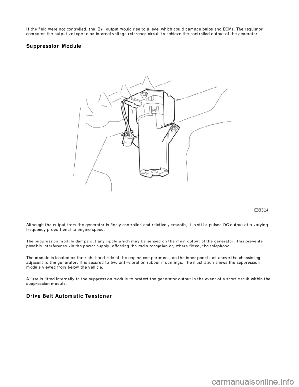
Suppression Module
Although the output from the generator is fi nely controlled and relatively smooth, it is still a pulsed DC output at a varying
frequency proportional to engine speed.
The suppression module damps ou t any ripple which may be sensed on the main output of the generator. This prevents
possible interference via the power supply, affecting the radio reception or, where fitted, the telephone.
The module is located on the right hand side of the engine compartment, on the inner panel just above the chassis leg,
adjacent to the generator. It is secured to two anti-vibration rubber moun tings. The illustration shows the suppression
module viewed from below the vehicle.
A fuse is fitted internally to the suppression module to protect the generator output in the event of a short circuit within th e
suppression module.
Drive Belt Automatic Tensioner
Page 1889 of 2490
CAUTION: The engine must not be running when multiplugs are connected or disconnected.
Check that the main B+ terminal is clean and tight.
Check that the IG terminal is clean and ma king good contact; if this connection is faulty, the generator will never function
correctly.
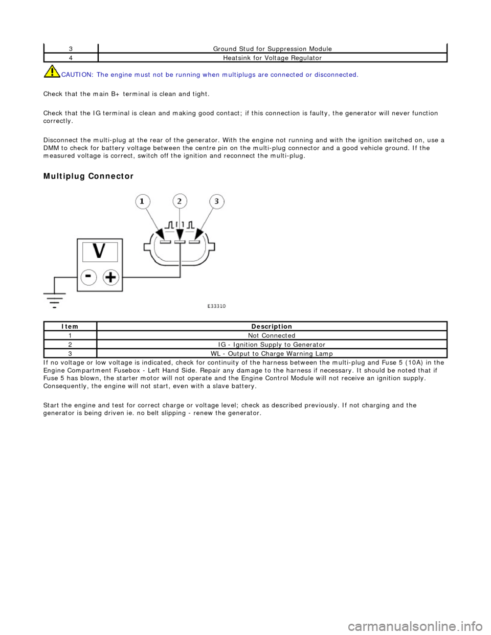
Disconnect the multi-plug at th e rear of the generator. With the engine not running and with the ignition switched on, use a
DMM to check for battery voltage between the centre pin on the multi-plug connector and a good vehicle ground. If the
measured voltage is correct, switch off the ignition and reconnect the multi-plug.
Multiplug Connector
If no voltage or low voltage is indicated, check for continuity of the harness between the multi-plug and Fuse 5 (10A) in the
Engine Compartment Fusebox - Left Hand Si de. Repair any damage to the harness if necessary. It should be noted that if
Fuse 5 has blown, the starter motor will not operate and the Engine Control Module will not receive an ignition supply.
Consequently, the engine will not st art, even with a slave battery.
Start the engine and test for correct ch arge or voltage level; check as described previously. If not charging and the
generator is being driven ie. no be lt slipping - renew the generator.
3Ground Stud for Suppression Module
4Heatsink for Voltage Regulator
ItemDescription
1Not Connected
2IG - Ignition Supply to Generator
3WL - Output to Charge Warning Lamp
Page 1908 of 2490
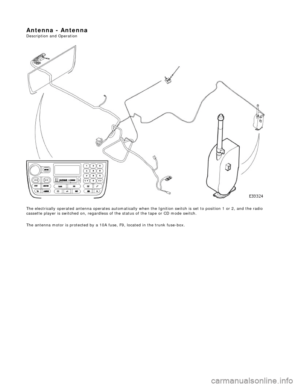
Antenna - Antenna
Description and Operation
The electrically operated antenna operates automatically when the Ignition switch is set to position 1 or 2, and the radio
cassette player is switched on , regardless of the status of the tape or CD mode switch.
The antenna motor is protected by a 10A fuse, F9, located in the trunk fuse-box.
Page 1909 of 2490

Antenna - Antenna
Diagnosis and Testing
Tests Using the Portable Diagnostic Unit
Refer to PDU User Guide
The PDU tests whether or not the antenna raises and lowers correctly. Although it is obvious if the antenna is not operating,
the PDU analyses why it is not operating an d indicates problems such as a faulty radio head signal output, faulty wiring, loss of power due to a blown fuse.