fuse JAGUAR X308 1998 2.G Service Manual
[x] Cancel search | Manufacturer: JAGUAR, Model Year: 1998, Model line: X308, Model: JAGUAR X308 1998 2.GPages: 2490, PDF Size: 69.81 MB
Page 1231 of 2490
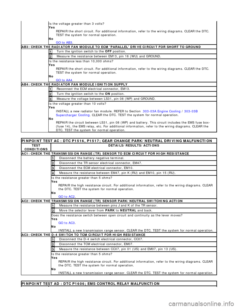
Is th
e voltage greater than 3 volts?
Yes REPAIR the short circuit. For addi tional information, refer to the wiring diagrams. CLEAR the DTC.
TEST the system for normal operation.
No GO to AB3
.
AB3
: CHECK THE RADIATOR FAN MODULE TO ECM
'PARALLEL' DRIVE CIRCUIT FOR SHORT TO GROUND
Turn the ignition swi
tch to the OFF
position.
1
Meas
ure the resistance between EM13, pin 16 (WU) and GROUND.
2
Is
the resistance less than 10,000 ohms?
Yes
REPAIR the short circuit. For addi tional information, refer to the wiring diagrams. CLEAR the DTC.
TEST the system for normal operation.
No GO to AA4
.
AB4
: CHECK THE RADIATOR FAN MODULE IGNITION SUPPLY
Re
connect the ECM electrical connector, EM13.
1
Turn the ignition swi
tch to the ON
position.
2
Measure the
voltage between LS
31, pin 08 (WP) and GROUND.
3
Is the vol
tage greater than 10 volts?
Yes INSTALL a new radiator fan module. REFER to Section 303
-0
3A Engine Cooling
/
30
3
-03
B
Supercharger
Cooling
. CLEA
R the DTC. TEST the sy
stem for normal operation.
No REPAIR the circuit between LS31, pin 08 (WP) and battery. This circuit includes the EMS fuse box-
(fuse 14), the EMS relay, etc. For additional information, refer to the wiring diagrams. CLEAR the
DTC. TEST the system for normal operation.
P
INPOINT TEST AC : DTC P1516, P1517; GEAR
CHANGE PARK/NEUTRAL DRIVING MALFUNCTION
TE
ST
CONDITIONS
D
ETAILS/RESULTS/ACTIONS
AC1: CH
ECK THE TRANSMISSION RANGE (TR) SE
NSOR TO ECM CIRCUIT FOR HIGH RESISTANCE
Di
sconnect the battery negative terminal.
1
Di
sconnect the TR sensor el
ectrical connector, EM47.
2
D
isconnect the ECM electrical connector, EM10.
3
Meas
ure the resistance between EM47, pin K (RU) and EM10, pin 15 (RU).
4
Is th
e resistance greater than 5 ohms?
Yes REPAIR the high resistance circui t. For additional information, refer to the wiring diagrams. CLEAR
the DTC. TEST the system for normal operation.
No GO to AC2
.
AC2: CH
ECK THE TRANSMISSION RANGE (TR)
SENSOR PARK/NEUTRAL SWITCHING ACTION
Meas
ure the resistance between pi
ns J and K of the TR sensor.
1
Mo
ve the selector lever from
PARK to NEUTRAL and back.
2
D
oes the resistance switch between open ci
rcuit and continuity as the lever moves?
Yes GO to AC3
.
No
INSTALL a new transmission range sensor. CLEAR th e DTC. TEST the system for normal operation.
AC3: CH
ECK THE D-4 SWITCH TO
TCM CIRCUIT FOR HIGH RESISTANCE
Di
sconnect the D-4 switch electrical connector, CC07.
1
Di
sconnect the TCM electrical connector, EM07.
2
Meas
ure the resistance between CC07,
pin 01 (US) and EM07, pin 13 (US).
3
Is th
e resistance greater than 5 ohms?
Yes REPAIR the high resistance circui t. For additional information, refer to the wiring diagrams. CLEAR
the DTC. TEST the system for normal operation.
No INSTALL a new transmission range sensor. CLEAR th e DTC. TEST the system for normal operation.
P
INPOINT TEST AD : DTC P1606;
EMS CONTROL RELAY MALFUNCTION
Page 1273 of 2490
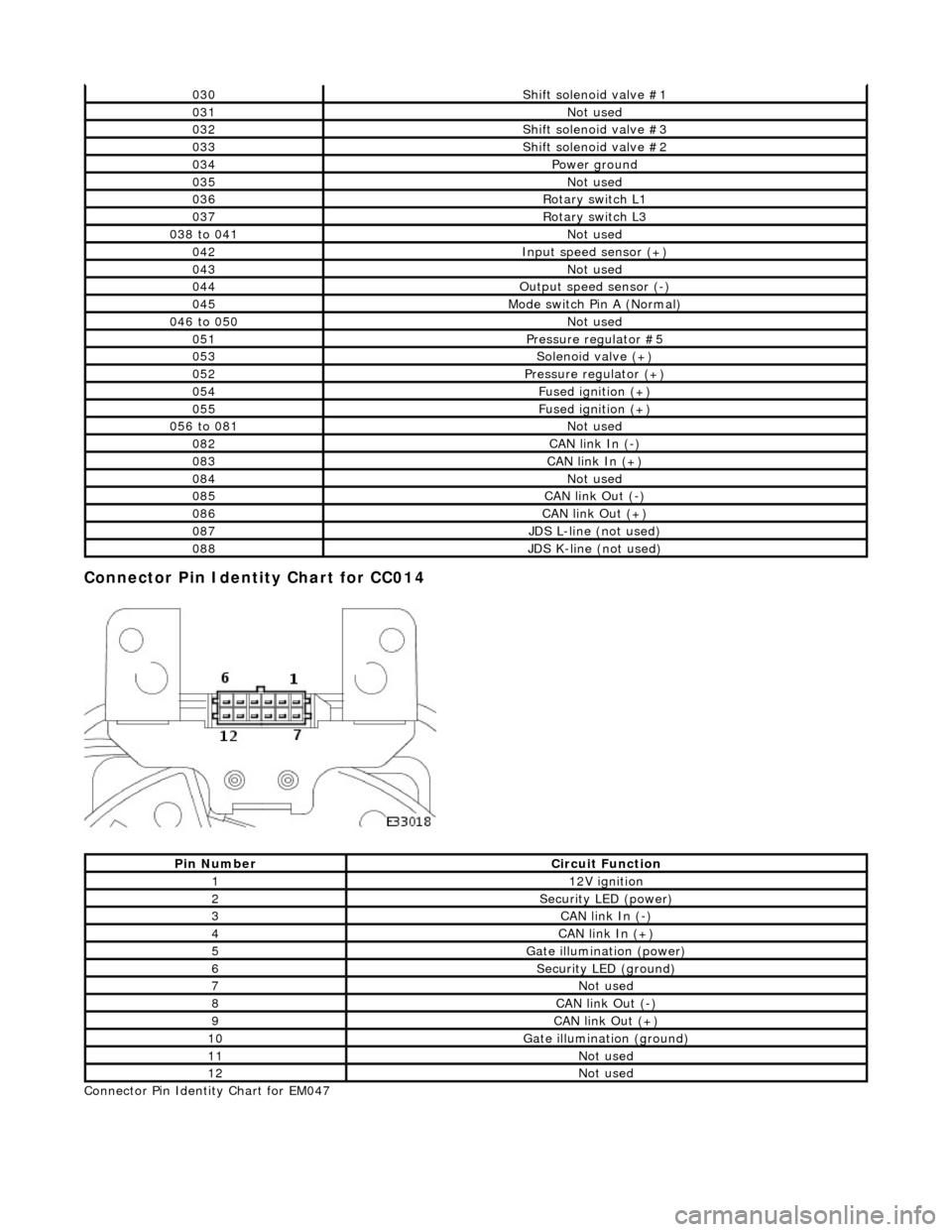
Connector Pin Identity Chart for CC014
Connector Pin Identity Chart for EM047
030Shift solenoid valve #1
031Not used
032Shift solenoid valve #3
033Shift solenoid valve #2
034Power ground
035Not used
036Rotary switch L1
037Rotary switch L3
038 to 041Not used
042Input speed sensor (+)
043Not used
044Output speed sensor (-)
045Mode switch Pin A (Normal)
046 to 050Not used
051Pressure regulator #5
053Solenoid valve (+)
052Pressure regulator (+)
054Fused ignition (+)
055Fused ignition (+)
056 to 081Not used
082CAN link In (-)
083CAN link In (+)
084Not used
085CAN link Out (-)
086CAN link Out (+)
087JDS L-line (not used)
088JDS K-line (not used)
Pin NumberCircuit Function
112V ignition
2Security LED (power)
3CAN link In (-)
4CAN link In (+)
5Gate illumination (power)
6Security LED (ground)
7Not used
8CAN link Out (-)
9CAN link Out (+)
10Gate illumination (ground)
11Not used
12Not used
Page 1278 of 2490
Pinpoint test A: P0741, P0742, P0743
Pinpoint test B: P0743
Connector pin(s) bent or tracking between
connections
*
DTC P1789 Ignition supply malfunction >7 < 9
voltsBattery charging system fault
Blown fuse
Harness fault
Connector loose or corroded
Connector pin(s) bent or tracking between
connections Ground fault
*
*
*
*
*
*GO to Pinpoint
Test K
*
DTC P0710 Transmission fluid temperature
sensor malfunctionDamaged sensor
Sensor out of range / short
Harness open circuit
Harness short
Connector loose or corroded
*
*
*
*
*GO to Pinpoint
Test L
*
PINPOINT TEST A : P0741, P0742, P0743
TEST CONDITIONSDETAILS/RESULTS/ACTIONS
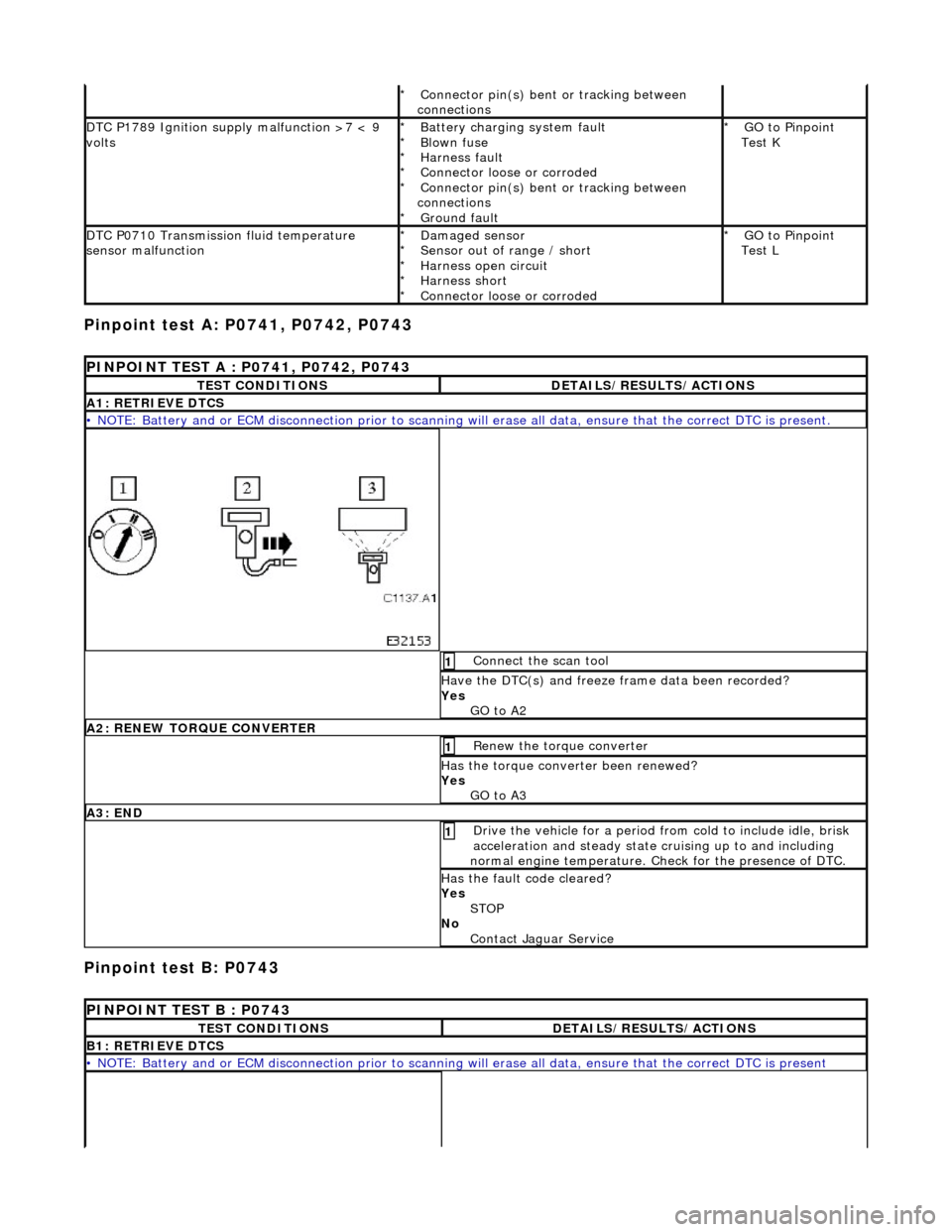
A1: RETRIEVE DTCS
• NOTE: Battery and or ECM disconnection prior to scanning wi
ll erase all data, ensure that the correct DTC is present.
Connect the scan tool 1
Have the DTC(s) and freeze frame data been recorded?
Yes GO to A2
A2: RENEW TORQUE CONVERTER
Renew the torque converter 1
Has the torque converter been renewed?
Yes GO to A3
A3: END
Drive the vehicle for a period from cold to include idle, brisk
acceleration and steady state cruising up to and including
normal engine temperature. Check for the presence of DTC. 1
Has the fault code cleared?
Yes STOP
No Contact Jaguar Service
PINPOINT TEST B : P0743
TEST CONDITIONSDETAILS/RESULTS/ACTIONS
B1: RETRIEVE DTCS
• NOTE: Battery and or ECM disconnection prior to scanning wi ll erase all data, ensure that the correct DTC is present
Page 1331 of 2490
Pinpoint test K: P1789, P1793
Connect the scan tool 1
Have the DTC(s) and freeze frame data been recorded?
Yes GO to J2
J2: RENEW TCM
Renew the TCM 1
Has the TCM been renewed?
Yes GO to J3
J3: END
Drive the vehicle for a period from cold to include idle, brisk
acceleration and steady state cruising up to and including
normal engine temperature. Check for the presence of DTC 1
Has the fault code cleared?
Yes STOP
No Contact Jaguar Service
PINPOINT TEST K : P1789, P1793
TEST CONDITIONSDETAILS/RESULTS/ACTIONS
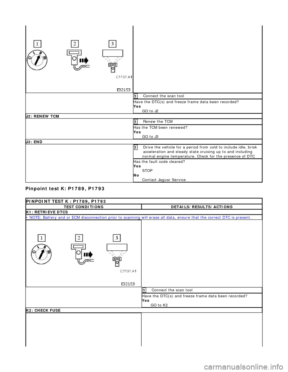
K1: RETRIEVE DTCS
• NOTE: Battery and or ECM disconnection prior to scanning wi ll erase all data, ensure that the correct DTC is present.
Connect the scan tool 1
Have the DTC(s) and freeze frame data been recorded?
Yes GO to K2
K2: CHECK FUSE
Page 1332 of 2490
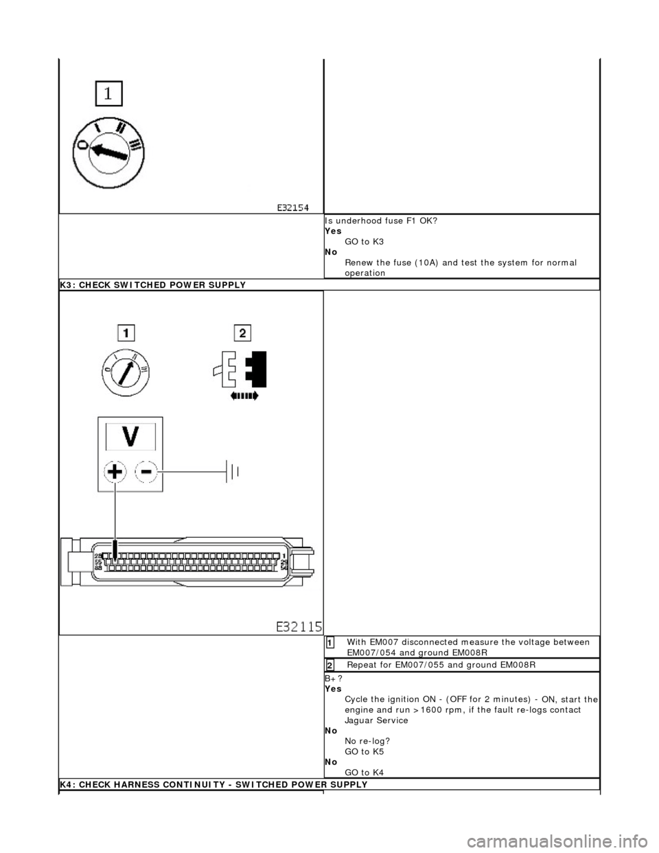
Is underhood fuse F1 OK?
Yes GO to K3
No Renew the fuse (10A) and te st the system for normal
operation
K3: CHECK SWITCHED POWER SUPPLY
With EM007 disconnected measure the voltage between
EM007/054 and ground EM008R 1
Repeat for EM007/055 and ground EM008R 2
B+?
Yes Cycle the ignition ON - (OFF for 2 minutes) -
ON, start the engine and run >1600 rpm, if the fault re-logs contact
Jaguar Service
No No re-log?
GO to K5
No GO to K4
K4: CHECK HARNESS CONTINUITY - SWITCHED POWER SUPPLY
Page 1396 of 2490
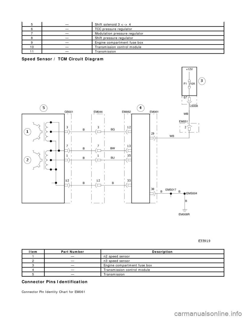
Speed Sensor / TCM Circuit Diagram
Connector Pins Identification
Connector Pin Identity Chart for EM061
5—Shift solenoid 3 <-> 4
6—TCC pressure regulator
7—Modulation pressure regulator
8—Shift pressure regulator
9—Engine compartment fuse box
10—Transmission control module
11—Transmission
ItemPart NumberDescription
1—n2 speed sensor
2—n3 speed sensor
3—Engine compartment fuse box
4—Transmission control module
5—Transmission
Page 1531 of 2490
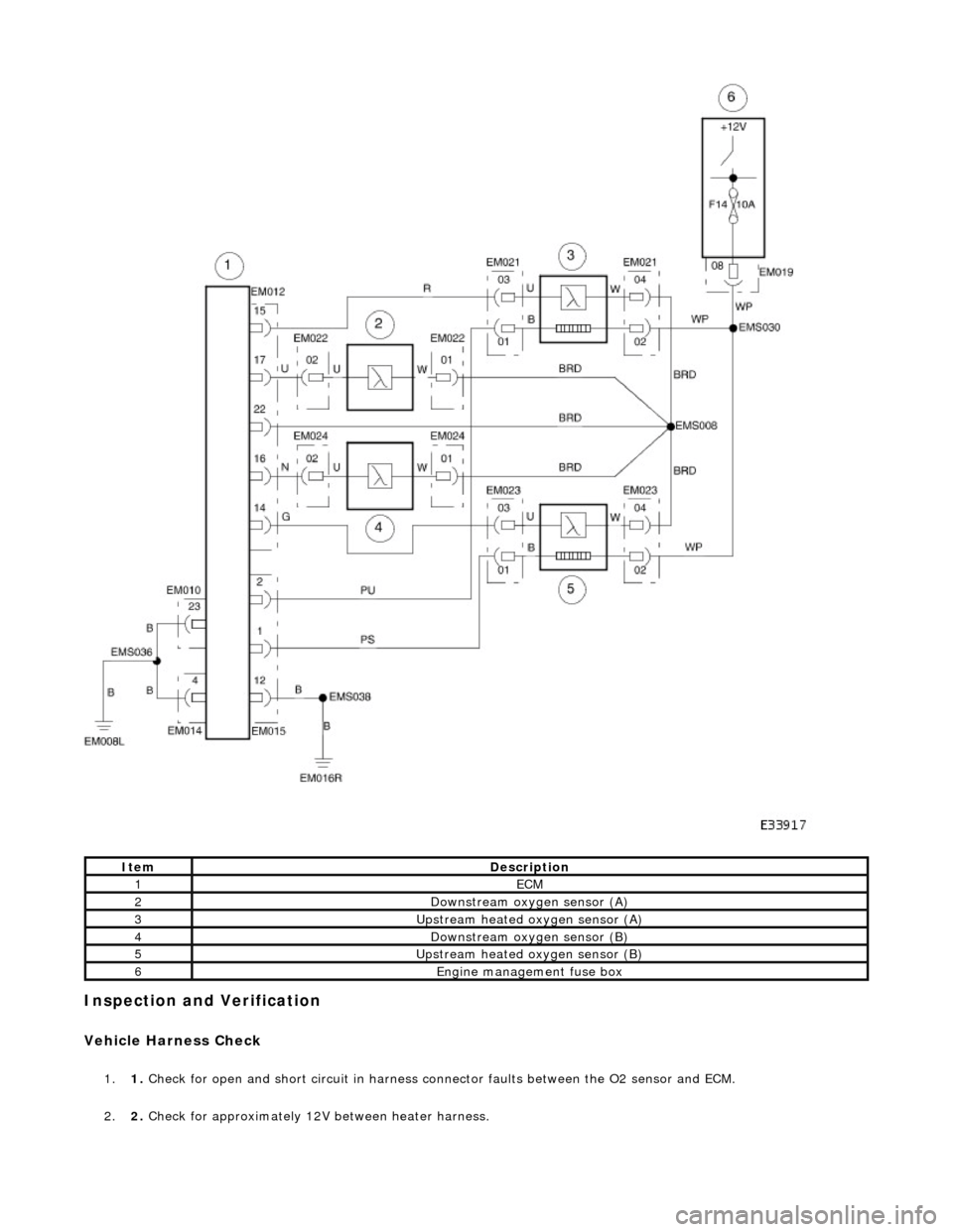
Inspection and Verification
Vehicle Harness Check
1.1. Check for open and short circuit in harness conn ector faults between the O2 sensor and ECM.
2. 2. Check for approximately 12V between heater harness.
ItemDescription
1ECM
2Downstream oxygen sensor (A)
3Upstream heated oxygen sensor (A)
4Downstream oxygen sensor (B)
5Upstream heated oxygen sensor (B)
6Engine management fuse box
Page 1544 of 2490
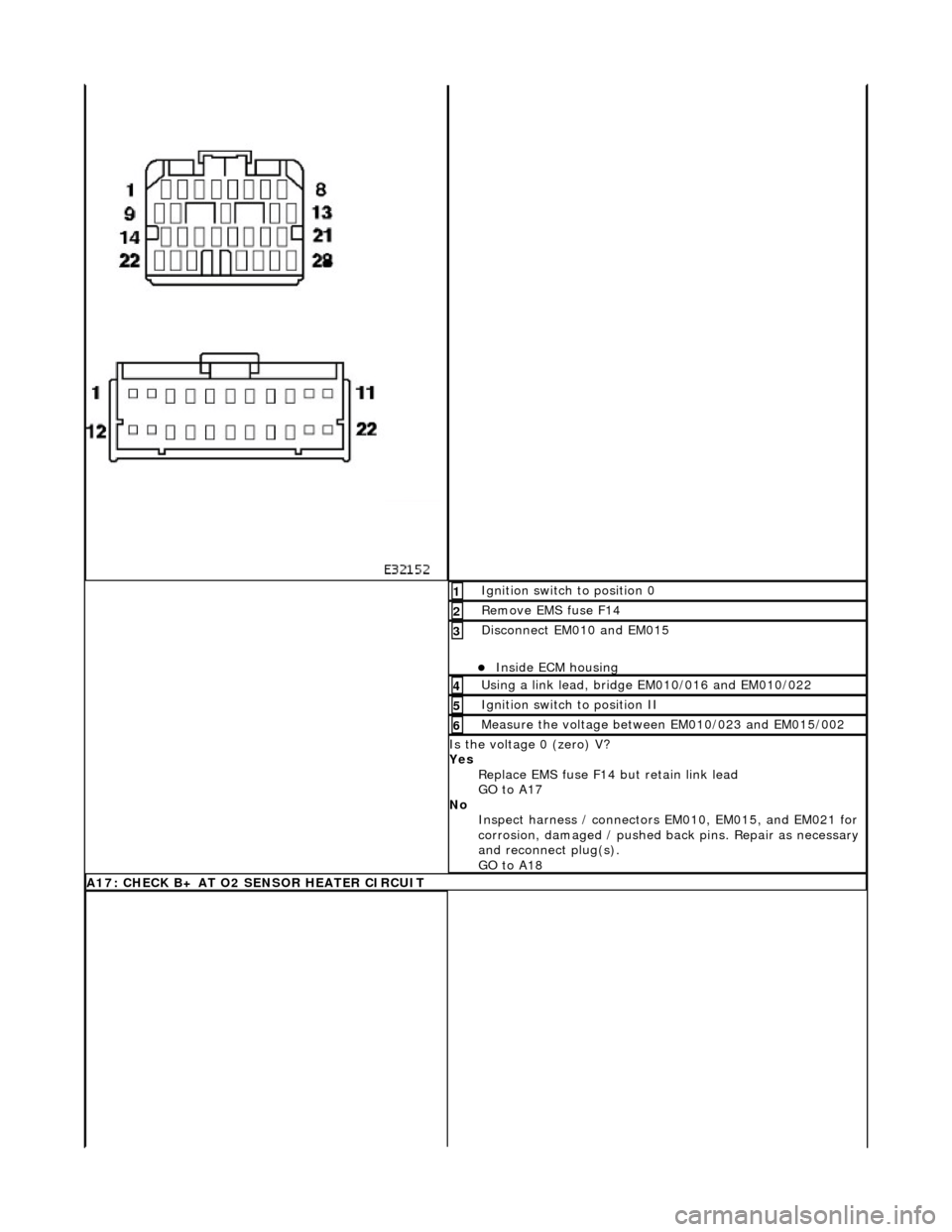
Ignition switch to position 0 1
Remove EMS fuse F14 2
Disconnect EM010 and EM015
Inside ECM housing
3
Using a link lead, bridge EM010/016 and EM010/022 4
Ignition switch to position II 5
Measure the voltage between EM010/023 and EM015/002 6
Is the voltage 0 (zero) V?
Yes Replace EMS fuse F14 but retain link lead
GO to A17
No Inspect harness / connectors EM010, EM015, and EM021 for
corrosion, damaged / pushed back pins. Repair as necessary
and reconnect plug(s).
GO to A18
A17: CHECK B+ AT O2 SENSOR HEATER CIRCUIT
Page 1545 of 2490
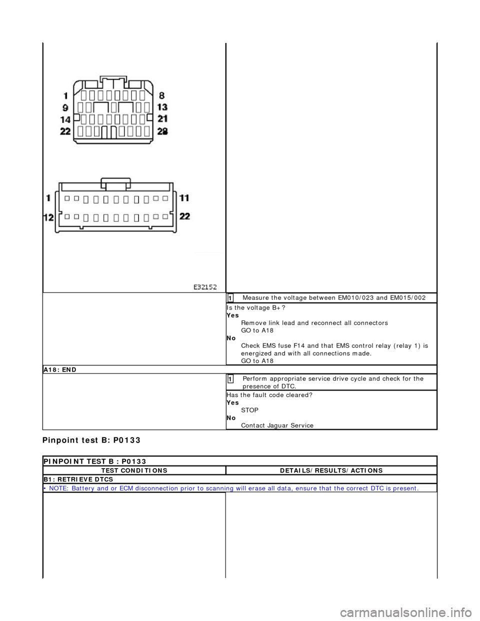
Pinpoint test B: P0133
Measure the voltage between EM010/023 and EM015/002 1
Is the voltage B+?
Yes Remove link lead and reconnect all connectors
GO to A18
No Check EMS fuse F14 and that EMS control relay (relay 1) is
energized and with all connections made.
GO to A18
A18: END
Perform appropriate service drive cycle and check for the
presence of DTC. 1
Has the fault code cleared?
Yes STOP
No Contact Jaguar Service
PINPOINT TEST B : P0133
TEST CONDITIONSDETAILS/RESULTS/ACTIONS
B1: RETRIEVE DTCS
• NOTE: Battery and or ECM disconnection prior to scanning wi ll erase all data, ensure that the correct DTC is present.
Page 1556 of 2490
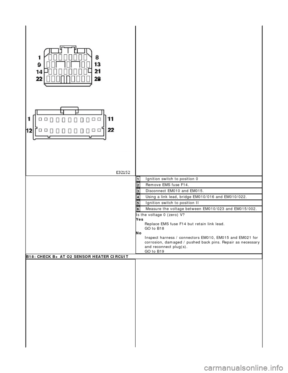
Ignition switch to position 0 1
Remove EMS fuse F14. 2
Disconnect EM010 and EM015. 3
Using a link lead, bridge EM010/016 and EM010/022. 4
Ignition switch to position II 5
Measure the voltage between EM010/023 and EM015/002. 6
Is the voltage 0 (zero) V?
Yes Replace EMS fuse F14 but retain link lead.
GO to B18
No Inspect harness / connectors EM010, EM015 and EM021 for
corrosion, damaged / pushed back pins. Repair as necessary
and reconnect plug(s).
GO to B19
B18: CHECK B+ AT O2 SENSOR HEATER CIRCUIT