relay JAGUAR X308 1998 2.G Repair Manual
[x] Cancel search | Manufacturer: JAGUAR, Model Year: 1998, Model line: X308, Model: JAGUAR X308 1998 2.GPages: 2490, PDF Size: 69.81 MB
Page 1222 of 2490
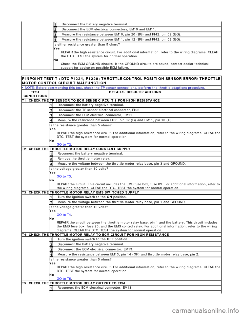
Disc
onnect the battery negative terminal.
1
D
i
sconnect the ECM electrical connectors, EM10 and EM11.
2
Meas
ure t
he resistance between EM10,
pin 20 (BG) and PI42, pin 02 (BG).
3
Measure t
he resistance between EM11,
pin 12 (BG) and PI42, pin 02 (BG).
4
Is either resistance greater
than 5 ohms?
Yes REPAIR the high resistance circui t. For additional information, refer to the wiring diagrams. CLEAR
the DTC. TEST the system for normal operation.
No Check the ECM GROUND circuits. If the GROUND circuits are sound, contact dealer technical
support for advice on possible ECM failure.
PINPOINT TES
T T : DTC P1224, P1229; THROTTLE
CONTROL POSITION SENSOR ERROR/THROTTLE
MOTOR CONTROL CIRCUIT MALFUNCTION
•
NOTE: Before commencing this test, check the TP sensor
connections, perform the throttle adaptions procedure.
TES
T
CONDITIONS
D E
TAILS/RESULTS/ACTIONS
T
1: CH
ECK THE TP SENSOR TO ECM SE
NSE CIRCUIT 1 FOR HIGH RESISTANCE
Disc
onnect the battery negative terminal.
1
Disc
onne
ct the TP sensor electrical connector, PI06.
2
D
i
sconnect the ECM electrical connector, EM11.
3
Me
asure
the resistance between PI06, pin 02 (G) and EM11, pin 10 (G).
4
Is th
e res
istance greater than 5 ohms?
Yes REPAIR the high resistance circuit. For additional information, refer to the wiring diagrams. CLEAR the
DTC. TEST the system for normal operation.
No GO to T2
.
T2
: CHECK THE THROTTLE MOTOR RELAY CONSTANT SUPPLY
R
e
connect the battery negative terminal.
1
R
e
move the thrott
le motor relay.
2
Measure t
he voltage between the throttle
motor relay base, pin 3 and GROUND.
3
Is the volt
age greater than 10 volts?
Yes GO to T3
.
No
R
EPAIR the circuit. This ci
rcuit includes the EMS fuse box, fuse 09. For addi tional information, refer to
the wiring diagrams. CLEAR the DTC. TE ST the system for normal operation.
T3
: CHECK THE THROTTLE MOTOR
RELAY EMS SWITCHED SUPPLY
Turn the ignition swit
ch to the
ON position.
1
Meas ure t
he voltage between the throttle
motor relay base, pin 1 and GROUND.
2
Is the volt
age greater than 10 volts?
Yes GO to T4
.
No
REP
AIR the circuit between the throttle motor relay
base, pin 1 and the battery. This circuit includes
the EMS fuse box, fuse 20, and the EMS control relay. For addition al information, refer to the wiring
diagrams. CLEAR the DTC. TEST th e system for normal operation.
T4
: CHECK THE THROTTLE MOTOR RELAY TO
ECM CIRCUIT FOR HIGH RESISTANCE
Turn the ignition swit
ch to the
OFF position.
1
Disc
onnect the battery negative terminal.
2
Di
sconnect the ECM electrical connector, EM13.
3
Measure t
he resistance between EM13, pin 14 (G
R) and throttle motor relay base, pin 2.
4
Is the res
istance greater than 5 ohms?
Yes REPAIR the high resistance circuit. For additional information, refer to the wiring diagrams. CLEAR the
DTC. TEST the system for normal operation.
No GO to T5
.
T5
: CHECK THE THROTTLE MOTOR RELAY OUTPUT TO ECM
Re
conn
ect the ECM electrical connector, EM13.
1
Page 1223 of 2490
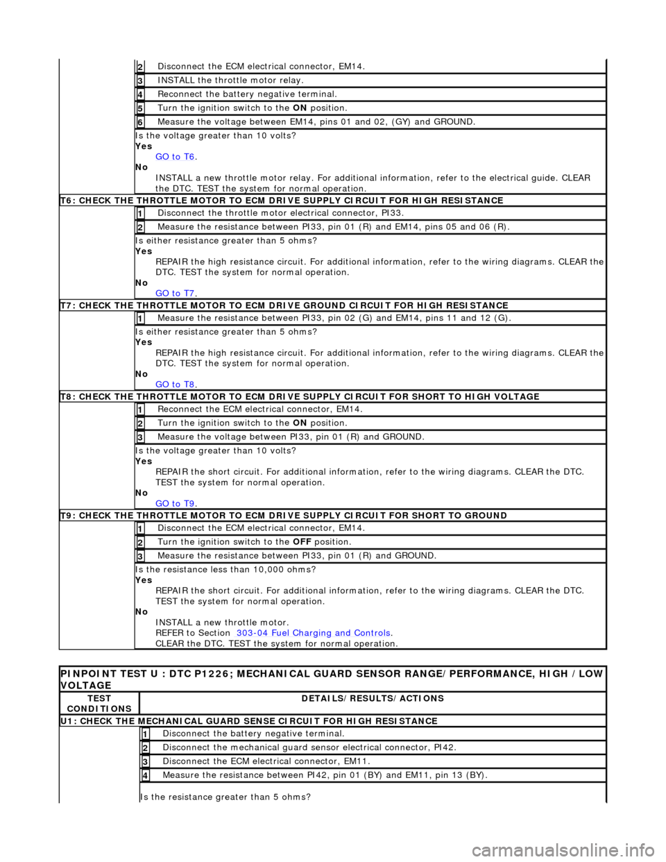
D
isconnect the ECM electrical connector, EM14.
2
IN
STALL the throttle motor relay.
3
R
econnect the battery negative terminal.
4
Turn the ignition swi
tch to the
ON position.
5
Measure the
voltage between EM14, pi
ns 01 and 02, (GY) and GROUND.
6
Is the vol
tage greater than 10 volts?
Yes GO to T6
.
No
INSTALL a new throttle motor relay. For additional information, refer to the electrical guide. CLEAR
the DTC. TEST the system for normal operation.
T
6: CHECK THE THROTTLE MOTOR TO ECM DRIVE SUPPLY CIRCUIT FOR HIGH RESISTANCE
Di
sconnect the throttle motor electrical connector, PI33.
1
Meas
ure the resistance between PI33, pi
n 01 (R) and EM14, pins 05 and 06 (R).
2
Is either resi
stance
greater than 5 ohms?
Yes REPAIR the high resistance circuit. For additional information, refer to the wiring diagrams. CLEAR the
DTC. TEST the system for normal operation.
No GO to T7
.
T
7: CHECK THE THROTTLE MOTOR TO ECM DRIVE GROUND CIRCUIT FOR HIGH RESISTANCE
Meas
ure the resistance between PI33, pin
02 (G) and EM14, pins 11 and 12 (G).
1
Is either resi
stance
greater than 5 ohms?
Yes REPAIR the high resistance circuit. For additional information, refer to the wiring diagrams. CLEAR the
DTC. TEST the system for normal operation.
No GO to T8
.
T
8: CHECK THE THROTTLE MOTOR TO ECM DRIVE SU
PPLY CIRCUIT FOR SHORT TO HIGH VOLTAGE
Re
connect the ECM electrical connector, EM14.
1
Turn the ignition swi
tch to the
ON position.
2
M
easure the voltage between PI33, pin 01 (R) and GROUND.
3
Is the vol
tage greater than 10 volts?
Yes REPAIR the short circuit. For addi tional information, refer to the wiring diagrams. CLEAR the DTC.
TEST the system for normal operation.
No GO to T9
.
T
9: CHECK THE THROTTLE MOTOR TO ECM DRIVE SUPPLY CIRCUIT FOR SHORT TO GROUND
D
isconnect the ECM electrical connector, EM14.
1
Turn the ignition swi
tch to the
OFF position.
2
Meas
ure the resistance between PI33, pin 01 (R) and GROUND.
3
Is
the resistance less than 10,000 ohms?
Yes REPAIR the short circuit. For addi tional information, refer to the wiring diagrams. CLEAR the DTC.
TEST the system for normal operation.
No INSTALL a new throttle motor.
REFER to Section 303
-0
4 Fuel Charging and Controls
.
CLEAR t
he DTC. TEST the system for normal operation.
P
INPOINT TEST U : DTC P1226; MECHANICAL
GUARD SENSOR RANGE/PERFORMANCE, HIGH /LOW
VOLTAGE
TE
ST
CONDITIONS
D
ETAILS/RESULTS/ACTIONS
U1: CHECK T
HE MECHANICAL GUARD SENSE CIRCUIT FOR HIGH RESISTANCE
Di
sconnect the battery negative terminal.
1
Di
sconnect the mechanical guard sensor electrical connector, PI42.
2
D
isconnect the ECM electrical connector, EM11.
3
Me
asure the resistance between PI42, pin 01 (BY) and EM11, pin 13 (BY).
4
Is th
e resistance greater than 5 ohms?
Page 1228 of 2490
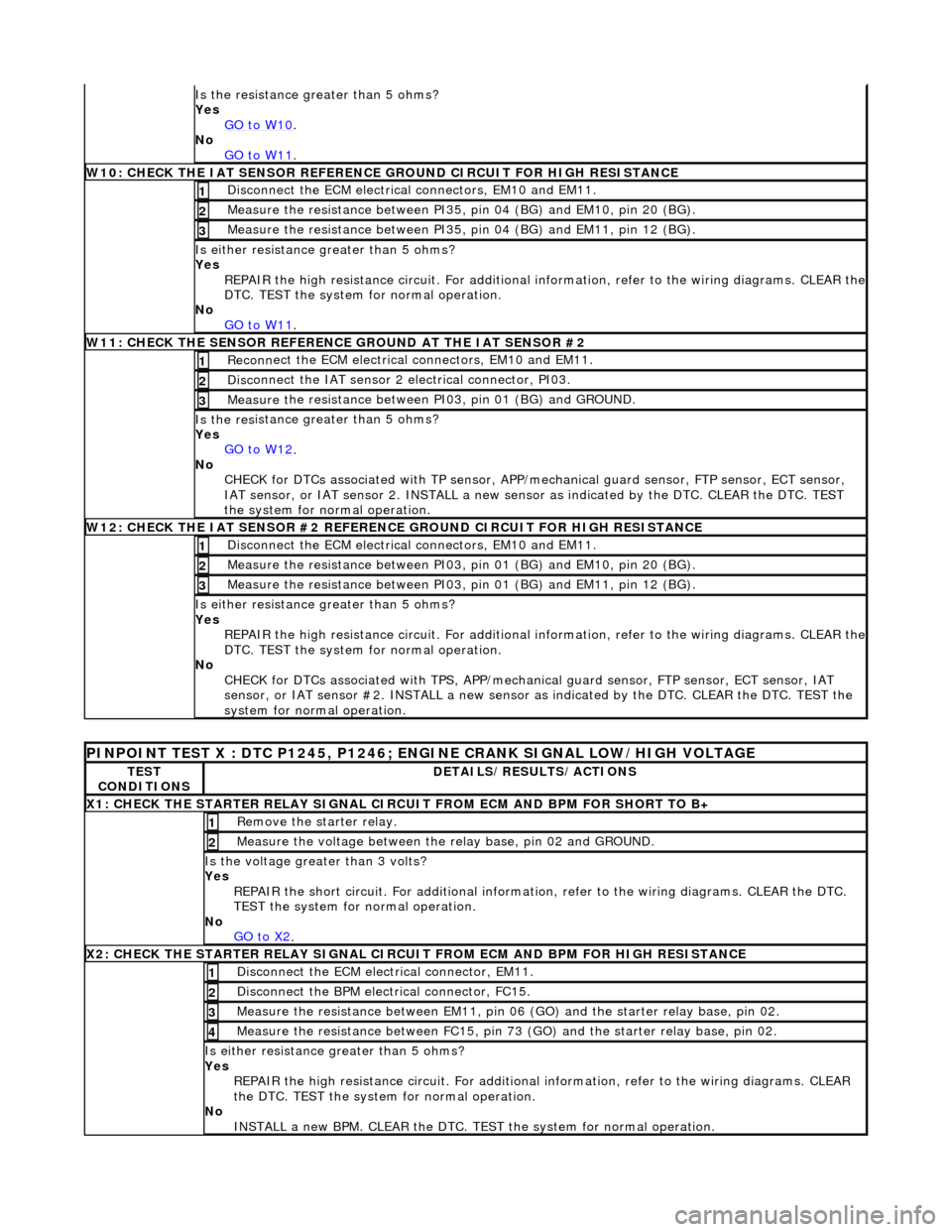
Is the res
istance greater than 5 ohms?
Yes GO to W10
.
No
GO to W11
.
W10 :
CHECK THE IAT SENSOR REFERENCE
GROUND CIRCUIT FOR HIGH RESISTANCE
Di
sconnect the ECM electrical connectors, EM10 and EM11.
1
Meas
ure t
he resistance between PI35,
pin 04 (BG) and EM10, pin 20 (BG).
2
Measure t
he resistance between PI35,
pin 04 (BG) and EM11, pin 12 (BG).
3
Is either resistance greater
than 5 ohms?
Yes REPAIR the high resistance circuit. For additional information, refer to the wiring diagrams. CLEAR the
DTC. TEST the system for normal operation.
No GO to W11
.
W11 :
CHECK THE SENSOR REFERENCE GROUND AT THE IAT SENSOR #2
Re
conn
ect the ECM electrical connectors, EM10 and EM11.
1
Di
sc
onnect the IAT sensor 2 electrical connector, PI03.
2
Meas
ure t
he resistance between PI03, pin 01 (BG) and GROUND.
3
Is th
e res
istance greater than 5 ohms?
Yes GO to W12
.
No
CHECK
for DTCs associated with TP sensor, APP/
mechanical guard sensor, FTP sensor, ECT sensor,
IAT sensor, or IAT sensor 2. INST ALL a new sensor as indicated by the DTC. CLEAR the DTC. TEST
the system for normal operation.
W12 :
CHECK THE IAT SENSOR #2 REFERENC
E GROUND CIRCUIT FOR HIGH RESISTANCE
Di
sconnect the ECM electrical connectors, EM10 and EM11.
1
Meas
ure t
he resistance between PI03,
pin 01 (BG) and EM10, pin 20 (BG).
2
Measure t
he resistance between PI03,
pin 01 (BG) and EM11, pin 12 (BG).
3
Is either resistance greater
than 5 ohms?
Yes REPAIR the high resistance circuit. For additional information, refer to the wiring diagrams. CLEAR the
DTC. TEST the system for normal operation.
No CHECK for DTCs associated with TPS, APP/mechanical guard sensor, FTP sensor, ECT sensor, IAT
sensor, or IAT sensor #2. INSTALL a new sensor as indicated by the DTC. CLEAR the DTC. TEST the
system for normal operation.
PINPO
INT TEST X : DTC P1245, P1246; ENGINE CRANK SIGNAL LOW/HIGH VOLTAGE
TE
S
T
CONDITIONS
D E
TAILS/RESULTS/ACTIONS
X
1
: CHECK THE STARTER RELAY SIGNAL CIRC
UIT FROM ECM AND BPM FOR SHORT TO B+
Re
move the starter relay.
1
Meas
ure t
he voltage between the
relay base, pin 02 and GROUND.
2
Is the volt
age greater than 3 volts?
Yes REPAIR the short circuit. For addi tional information, refer to the wiring diagrams. CLEAR the DTC.
TEST the system for normal operation.
No GO to X2
.
X2
: CHECK THE STARTER RELAY SIGNAL CIRCUI
T FROM ECM AND BPM FOR HIGH RESISTANCE
Di
sconnect the ECM electrical connector, EM11.
1
Disc
onne
ct the BPM electrical connector, FC15.
2
Meas
ure t
he resistance between EM11, pin 06
(GO) and the starter relay base, pin 02.
3
Measure t
he resistance between FC15, pin 73
(GO) and the starter relay base, pin 02.
4
Is either resistance greater
than 5 ohms?
Yes REPAIR the high resistance circui t. For additional information, refer to the wiring diagrams. CLEAR
the DTC. TEST the system for normal operation.
No INSTALL a new BPM. CLEAR the DTC. TEST the system for normal operation.
Page 1229 of 2490

P
INPOINT TEST Y : DTC P1260; SECURITY INPUT MALFUNCTION
TE
ST
CONDITIONS
D
ETAILS/RESULTS/ACTIONS
Y1
: CHECK THE KTM TO ECM CIRCUIT FOR HIGH RESISTANCE
D
isconnect the ECM electrical connector, EM10.
1
D
isconnect the KTM electrical connector, FC22.
2
Me
asure the resistance between EM10, pin 06 (O) and FC22, pin 16 (O).
3
Is th
e resistance greater than 5 ohms?
Yes REPAIR the high resistance circui t. For additional information, refer to the wiring diagrams. CLEAR
the DTC. TEST the system for normal operation.
No INSTALL a new KTM. CLEAR the DTC. TEST the system for normal operation.
PINPO
INT TEST Z : DTC P1474; INTERCOOLER COOLANT PUMP RELAY MALFUNCTION
•
NOTE: Early production vehicl
es have connector pin numbers that differ fro m the volume production pin numbers shown.
Use the wire color code for pin identifi cation on early production vehicles.
TE
ST
CONDITIONS
D
ETAILS/RESULTS/ACTIONS
Z1
: CHECK THE INTERCOOLER PUMP RELAY TO ECM DRIVE CIRCUIT FOR HIGH RESISTANCE
Di
sconnect the battery negative terminal.
1
R
emove the intercooler pump relay.
2
D
isconnect the ECM electrical connector, EM13.
3
Meas
ure the resistance between the rela
y base, pin 01 and EM13, pin 10 (RY).
4
Is th
e resistance greater than 5 ohms?
Yes REPAIR the high resistance circui t. For additional information, refer to the wiring diagrams. CLEAR
the DTC. TEST the system for normal operation.
No GO to Z2
.
Z2
: CHECK THE INTERCOOLER PUMP RELAY TO EC
M DRIVE CIRCUIT FOR SHORT TO HIGH VOLTAGE
R
econnect the battery negative terminal.
1
Turn the ignition swi
tch to the ON
position.
2
Meas
ure the voltage between the
relay base, pin 01 and GROUND.
3
Is th
e voltage greater than 3 volts?
Yes REPAIR the short circuit. For addi tional information, refer to the wiring diagrams. CLEAR the DTC.
TEST the system for normal operation.
No GO to Z3
.
Z3
: CHECK THE INTERCOOLER PUMP RELAY TO
ECM DRIVE CIRCUIT FOR SHORT TO GROUND
Turn the ignition swi
tch to the OFF
position.
1
Meas
ure the resistance between th
e relay base, pin 01 and GROUND.
2
Is
the resistance less than 10,000 ohms?
Yes
REPAIR the short circuit. For addi tional information, refer to the wiring diagrams. CLEAR the DTC.
TEST the system for normal operation.
No GO to Z4
.
Z4: CHECK THE INTER
COOLER PUMP RELAY GROUND CIRCUIT
Meas
ure the resistance between th
e relay base, pin 02 and GROUND.
1
Is th
e resistance greater than 5 ohms?
Yes REPAIR the high resistance circui t. For additional information, refer to the wiring diagrams. CLEAR
the DTC. TEST the system for normal operation.
No INSTALL a new intercooler pump re lay. CLEAR the DTC. TEST the system for normal operation.
P
INPOINT TEST AA : DTC P1475; RADIATOR
FANS SLOW (SERIES) CIRCUIT MALFUNCTION
TE
ST
CONDITIONS
D
ETAILS/RESULTS/ACTIONS
Page 1230 of 2490
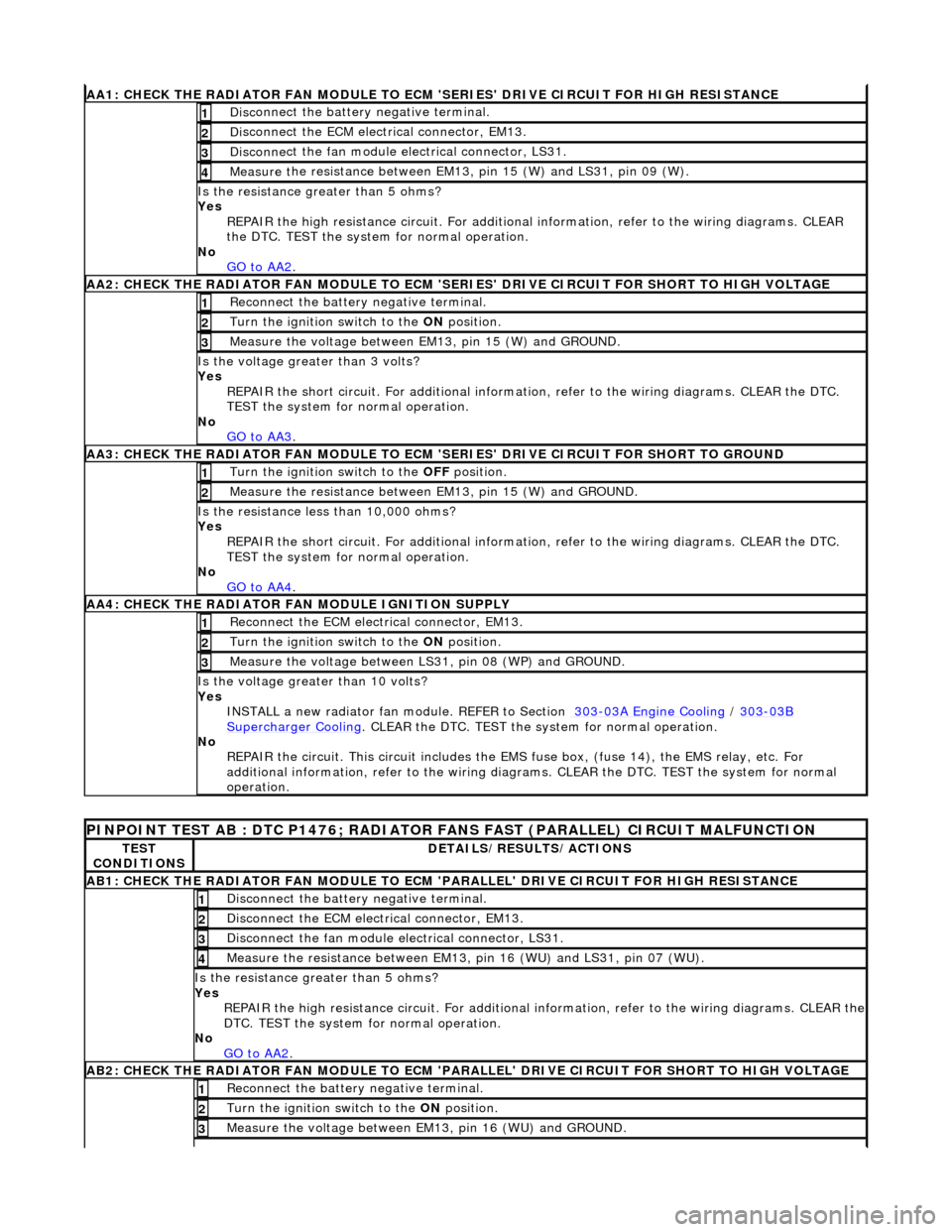
AA1: CHECK THE RA
DIATOR FAN MODULE TO ECM
'SERIES' DRIVE CIRCUIT FOR HIGH RESISTANCE
Disc
onnect the battery negative terminal.
1
D
i
sconnect the ECM electrical connector, EM13.
2
Disc
onne
ct the fan module electrical connector, LS31.
3
Meas
ure t
he resistance between EM13, pin 15 (W) and LS31, pin 09 (W).
4
Is th
e res
istance greater than 5 ohms?
Yes REPAIR the high resistance circui t. For additional information, refer to the wiring diagrams. CLEAR
the DTC. TEST the system for normal operation.
No GO to AA2
.
AA2: CHECK THE RA
DIATOR FAN MODULE TO ECM 'SER
IES' DRIVE CIRCUIT FOR SHORT TO HIGH VOLTAGE
Re
connect the battery negative terminal.
1
Turn the ignition swit
ch to the
ON position.
2
Measure t
he voltage between EM13, pin 15 (W) and GROUND.
3
Is the volt
age greater than 3 volts?
Yes REPAIR the short circuit. For addi tional information, refer to the wiring diagrams. CLEAR the DTC.
TEST the system for normal operation.
No GO to AA3
.
AA3: CHECK THE R A
DIATOR FAN MODULE TO ECM
'SERIES' DRIVE CIRCUIT FOR SHORT TO GROUND
Turn the ignition swit
ch to the
OFF position.
1
Meas ure t
he resistance between EM13, pin 15 (W) and GROUND.
2
Is
t
he resistance less than 10,000 ohms?
Yes
REPAIR the short circuit. For addi tional information, refer to the wiring diagrams. CLEAR the DTC.
TEST the system for normal operation.
No GO to AA4
.
AA4:
CHECK THE RADIATOR FAN MODULE IGNITION SUPPLY
Reconn
ect the ECM electrical connector, EM13.
1
Turn the ignition swit
ch to the
ON position.
2
Measure the voltage between LS 31,
pin 08 (WP) and GROUND.
3
Is the vol
t
age greater than 10 volts?
Yes INSTALL a new radiator fan module. REFER to Section 303
-03
A Engine Cooling
/
303-03B Supercharger Cooli
ng
. CLEA
R the DTC. TEST the sy stem f
or normal operation.
No REPAIR the circuit. This circui t includes the EMS fuse box, (f use 14), the EMS relay, etc. For
additional information, refer to the wiring diagrams. CLEAR the DT C. TEST the system for normal
operation.
PINPOINT TE ST
AB : DTC P1476; RADIATOR
FANS FAST (PARALLEL) CIRCUIT MALFUNCTION
TES
T
CONDITIONS
D E
TAILS/RESULTS/ACTIONS
AB1
:
CHECK THE RADIATOR FAN MODULE TO ECM
'PARALLEL' DRIVE CIRCUIT FOR HIGH RESISTANCE
Disc
onnect the battery negative terminal.
1
D
i
sconnect the ECM electrical connector, EM13.
2
Disc
onne
ct the fan module electrical connector, LS31.
3
Meas
ure t
he resistance between EM13, pin 16 (WU) and LS31, pin 07 (WU).
4
Is th
e res
istance greater than 5 ohms?
Yes REPAIR the high resistance circuit. For additional information, refer to the wiring diagrams. CLEAR the
DTC. TEST the system for normal operation.
No GO to AA2
.
AB2:
CHECK THE RADIATOR FAN MODULE TO ECM 'PARALLEL' DRIVE CIRCUIT FOR SHORT TO HIGH VOLTAGE
R
e
connect the battery negative terminal.
1
Turn the ignition swi
t
ch to the ON
position.
2
Measure t
he voltage between EM13, pin 16 (WU) and GROUND.
3
Page 1231 of 2490
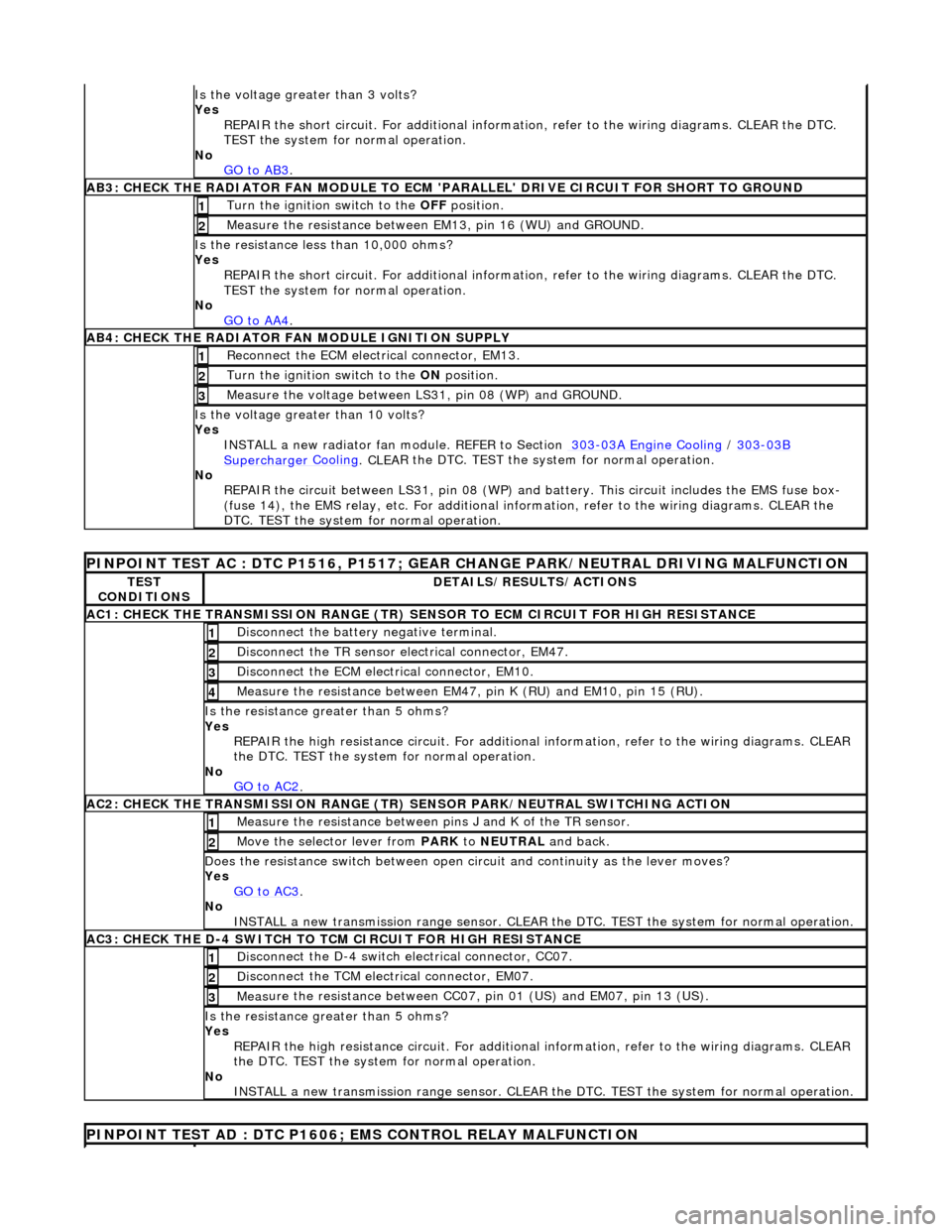
Is th
e voltage greater than 3 volts?
Yes REPAIR the short circuit. For addi tional information, refer to the wiring diagrams. CLEAR the DTC.
TEST the system for normal operation.
No GO to AB3
.
AB3
: CHECK THE RADIATOR FAN MODULE TO ECM
'PARALLEL' DRIVE CIRCUIT FOR SHORT TO GROUND
Turn the ignition swi
tch to the OFF
position.
1
Meas
ure the resistance between EM13, pin 16 (WU) and GROUND.
2
Is
the resistance less than 10,000 ohms?
Yes
REPAIR the short circuit. For addi tional information, refer to the wiring diagrams. CLEAR the DTC.
TEST the system for normal operation.
No GO to AA4
.
AB4
: CHECK THE RADIATOR FAN MODULE IGNITION SUPPLY
Re
connect the ECM electrical connector, EM13.
1
Turn the ignition swi
tch to the ON
position.
2
Measure the
voltage between LS
31, pin 08 (WP) and GROUND.
3
Is the vol
tage greater than 10 volts?
Yes INSTALL a new radiator fan module. REFER to Section 303
-0
3A Engine Cooling
/
30
3
-03
B
Supercharger
Cooling
. CLEA
R the DTC. TEST the sy
stem for normal operation.
No REPAIR the circuit between LS31, pin 08 (WP) and battery. This circuit includes the EMS fuse box-
(fuse 14), the EMS relay, etc. For additional information, refer to the wiring diagrams. CLEAR the
DTC. TEST the system for normal operation.
P
INPOINT TEST AC : DTC P1516, P1517; GEAR
CHANGE PARK/NEUTRAL DRIVING MALFUNCTION
TE
ST
CONDITIONS
D
ETAILS/RESULTS/ACTIONS
AC1: CH
ECK THE TRANSMISSION RANGE (TR) SE
NSOR TO ECM CIRCUIT FOR HIGH RESISTANCE
Di
sconnect the battery negative terminal.
1
Di
sconnect the TR sensor el
ectrical connector, EM47.
2
D
isconnect the ECM electrical connector, EM10.
3
Meas
ure the resistance between EM47, pin K (RU) and EM10, pin 15 (RU).
4
Is th
e resistance greater than 5 ohms?
Yes REPAIR the high resistance circui t. For additional information, refer to the wiring diagrams. CLEAR
the DTC. TEST the system for normal operation.
No GO to AC2
.
AC2: CH
ECK THE TRANSMISSION RANGE (TR)
SENSOR PARK/NEUTRAL SWITCHING ACTION
Meas
ure the resistance between pi
ns J and K of the TR sensor.
1
Mo
ve the selector lever from
PARK to NEUTRAL and back.
2
D
oes the resistance switch between open ci
rcuit and continuity as the lever moves?
Yes GO to AC3
.
No
INSTALL a new transmission range sensor. CLEAR th e DTC. TEST the system for normal operation.
AC3: CH
ECK THE D-4 SWITCH TO
TCM CIRCUIT FOR HIGH RESISTANCE
Di
sconnect the D-4 switch electrical connector, CC07.
1
Di
sconnect the TCM electrical connector, EM07.
2
Meas
ure the resistance between CC07,
pin 01 (US) and EM07, pin 13 (US).
3
Is th
e resistance greater than 5 ohms?
Yes REPAIR the high resistance circui t. For additional information, refer to the wiring diagrams. CLEAR
the DTC. TEST the system for normal operation.
No INSTALL a new transmission range sensor. CLEAR th e DTC. TEST the system for normal operation.
P
INPOINT TEST AD : DTC P1606;
EMS CONTROL RELAY MALFUNCTION
Page 1232 of 2490

TES
T
CONDITIONS
D E
TAILS/RESULTS/ACTIONS
AD1
:
CHECK THE EMS RELAY PERMANENT B+ SUPPLY
R
e
move the EMS relay.
1
Meas
ure t
he voltage between the rela
y base, pins 02 and 03 and GROUND.
2
Are both vol
tages greater than 10 volts?
Yes GO to AD2
.
No
R
EPAIR the circuit between the rela
y base and battery. This circuit includes the high power protection
module. For additional information, refer to the wiring diagrams. CLEAR the DTC. TEST the system
for normal operation.
AD2 :
CHECK THE EMS RELAY TO ECM CIRCUIT FOR HIGH RESISTANCE
Di
sc
onnect the battery negative terminal.
1
D
i
sconnect the ECM electrical connector, EM10.
2
Meas
ure t
he resistance between the rela
y base, pin 01 and EM10, pin 16 (PK).
3
Is the res
istance greater than 5 ohms?
Yes REPAIR the high resistance circui t. For additional information, refer to the wiring diagrams. CLEAR
the DTC. TEST the system for normal operation.
No INSTALL a new EMS relay. CLEAR the DTC. TEST the system for normal operation.
PINPOINT TEST AE : CHECK
ROCHESTER VALVE FUNCTION
T
E
ST CONDITIONS
D
E
TAILS/RESULTS/ACTIONS
AE1: CHEC
K VAC
UUM INTEGRITY OF ROCHESTER VALVE
Di
sc
onnect hoses from the Rochester valve.
1
Bl
a
nk off outlet side of valve.
2
Con
n
ect a hand-held vacuum pump to the vacuum inlet of the valve.
3
Appl
y a vacuum t
o the valve and mo
nitor the reading for 2 minutes.
4
Do
es the valve hold vacuum?
Yes Inspect the pipes at either side of the valve for leaks/damage. Rectify as necessary.
No INSTALL a new Rochester valve. TEST the system for normal operation.
Page 1265 of 2490
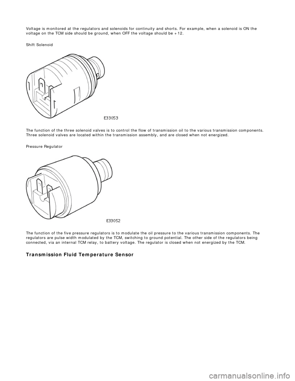
Voltage is monitored at the regulators and solenoids for continuity and shorts. For example, when a solenoid is ON the
voltage on the TCM side should be ground , when OFF the voltage should be +12.
Shift Solenoid
The function of the three soleno id valves is to control the flow of transmissi on oil to the various transmission components.
Three solenoid valves are located wi thin the transmission assembly, and are closed when not energized.
Pressure Regulator
The function of the five pressu re regulators is to modulate the oil pressure to the various transmission components. The
regulators are pulse width modulated by the TCM, switching to ground potential. The other side of the regulators being
connected, via an internal TCM relay, to battery voltage. The regulator is closed when not energized by the TCM.
Transmission Fluid Temperature Sensor
Page 1545 of 2490
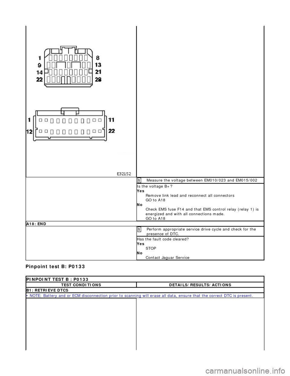
Pinpoint test B: P0133
Measure the voltage between EM010/023 and EM015/002 1
Is the voltage B+?
Yes Remove link lead and reconnect all connectors
GO to A18
No Check EMS fuse F14 and that EMS control relay (relay 1) is
energized and with all connections made.
GO to A18
A18: END
Perform appropriate service drive cycle and check for the
presence of DTC. 1
Has the fault code cleared?
Yes STOP
No Contact Jaguar Service
PINPOINT TEST B : P0133
TEST CONDITIONSDETAILS/RESULTS/ACTIONS
B1: RETRIEVE DTCS
• NOTE: Battery and or ECM disconnection prior to scanning wi ll erase all data, ensure that the correct DTC is present.
Page 1557 of 2490

Pinpoint test C: P0137, P0138
Measure the voltage between EM010/023 and EM015/002. 1
Is the voltage B+?
Yes Remove link lead and reconnect all connectors.
GO to B19
No Check EMS fuse F14 and that EMS control relay (relay 1) is
energized and with all connections made.
GO to B19
B19: END
Perform appropriate service drive cycle and check for the
presence of DTC 1
Has the fault code cleared?
Yes STOP
No Contact Jaguar Service
PINPOINT TEST C : P0137, P0138
TEST CONDITIONSDETAILS/RESULTS/ACTIONS
C1: RETRIEVE DTCS
• NOTE: Battery and or ECM disconnection prior to scanning wi ll erase all data, ensure that the correct DTC is present.