Crankshaft sensor JAGUAR X308 1998 2.G Manual PDF
[x] Cancel search | Manufacturer: JAGUAR, Model Year: 1998, Model line: X308, Model: JAGUAR X308 1998 2.GPages: 2490, PDF Size: 69.81 MB
Page 1179 of 2490

generates a signal when th
e dr
ive plate passes the sensor
sen
ds the ECM signals indicating crankshaft position and engine speed
is e
ssential for calculating spark timing
En
gine Coolant Temperature (ECT) Sensor
sen
ds the ECM a signal indicating the temperature of the engine coolant
is a t
emperature dependent resistor with a negative temperature coefficient (resistance changes inversely with
respect to temperature) and is constantly monitored by the ECM
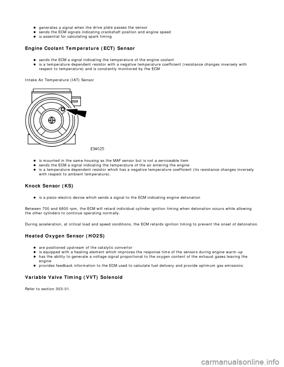
Intake Air Temperature (IAT) Sensor
is m
ounted in the same housing as the MA
F sensor but is not a serviceable item
sen
ds the ECM a signal indicating the temperature of the air entering the engine
is a t
emperature dependent resistor which has a negative
temperature coefficient (its resistance changes inversely
with respect to ambient temperature).
Knock S
ensor (KS)
is a pi
ezo-electric device which sends a signal
to the ECM indicating engine detonation
Between 700 and 6800 rpm, the ECM will retard individual cylinder ignition timing when detonation occurs while allowing
the other cylinders to continue operating normally.
During acceleration, at critical load and speed conditions, the ECM retards ignition timing to prevent the onset of detonation.
H
eated Oxygen Sensor (HO2S)
are
positioned upstream of the catalytic convertor
is equipped with
a heating element wh
ich improves the response time of the sensors during engine warm-up
h
as the ability to generate a voltage signal proportional to the oxygen content of the exhaust gases leaving the
engine
pr
ovides feedback information to the ECM used to calc
ulate fuel delivery and provide optimum gas emissions
Variable V
alve Timing (VVT) Solenoid
R
efer to section 303-01.
Page 1185 of 2490

It
em
Par
t Number
De
scription
1—Cranksh
aft position sensor
2—Engine
control module (ECM)
Crankshaft Posi
tion sensor
Page 1216 of 2490

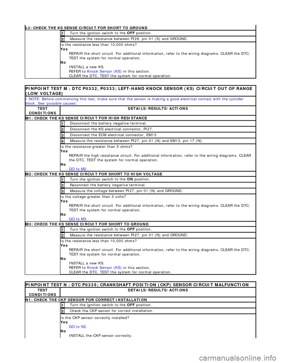
L3
: CHECK THE KS SENSE CIRCUIT FOR SHORT TO GROUND
Turn the ignition swi
t
ch to the OFF
position.
1
Me
asure the resistance between PI26, pin 01 (S) and GROUND.
2
Is
t
he resistance less than 10,000 ohms?
Yes REPAIR the short circuit. For addi tional information, refer to the wiring diagrams. CLEAR the DTC.
TEST the system for normal operation.
No INSTALL a new KS.
REFER to Knock Sensor (KS)
in this
section.
CLEAR the DTC. TEST the system for normal operation.
P INPOINT TES
T M : DTC P0332, P0333; LEFT-H
AND KNOCK SENSOR (KS) CIRCUIT OUT OF RANGE
(LOW VOLTAGE)
•
NOTE: Before commencing this
test, make sure that the sensor is making a good electrical contact with the cylinder
block. See 'possible causes'.
TE S
T
CONDITIONS
D E
TAILS/RESULTS/ACTIONS
M1: CHECK THE KS SEN
S
E CI
RCUIT FOR HIGH RESISTANCE
Di
sc
onnect the battery negative terminal.
1
Di
sc
onnect the KS electrical connector, PI27.
2
D
i
sconnect the ECM electrical connector, EM13.
3
M
e
asure the resistance between PI27, pin 01 (N) and EM13, pin 17 (N).
4
Is th
e res
istance greater than 5 ohms?
Yes REPAIR the high resistance circui t. For additional information, refer to the wiring diagrams. CLEAR
the DTC. TEST the system for normal operation.
No GO to M2
.
M2: CHECK TH
E KS SENSE CIRCUIT FOR SHORT TO HIGH VOLTAGE
Turn the ignition swi
t
ch to the ON
position.
1
Re
connect the battery negative terminal.
2
Meas
ure t
he voltage between PI27, pin 01 (N) and GROUND.
3
Is th
e volt
age greater than 3 volts?
Yes REPAIR the short circuit. For addi tional information, refer to the wiring diagrams. CLEAR the DTC.
TEST the system for normal operation.
No GO to M3
.
M3: CHECK TH
E KS SENSE CIRCUIT FOR SHORT TO GROUND
Turn the ignition swi
t
ch to the OFF
position.
1
Measure t
he resistance between PI27, pin 01 (N) and GROUND.
2
Is
t
he resistance less than 10,000 ohms?
Yes REPAIR the short circuit. For addi tional information, refer to the wiring diagrams. CLEAR the DTC.
TEST the system for normal operation.
No INSTALL a new KS.
REFER to Knock Sensor (KS)
in this
section.
CLEAR the DTC. TEST the system for normal operation.
PINPOINT TEST N : DTC P0335;
CRANKSHAFT POSITION (CKP) SENSOR CIRCUIT MALFUNCTION
TE
S
T
CONDITIONS
D E
TAILS/RESULTS/ACTIONS
N
1: CH
ECK THE CKP SENSOR FOR CORRECT INSTALLATION
Turn the ignition swi
t
ch to the OFF
position.
1
Check the CKP sen
sor fo
r correct installation.
2
Is the CK
P sensor correctly installed?
Yes GO to N2
.
No
INST
ALL the CKP sensor correctly.
Page 1217 of 2490

REF
ER to
Crankshaft Position (CKP) Sensor
in this section.
Reconnect the sensor. CLEAR the DTCs. TE ST the system for normal operation.
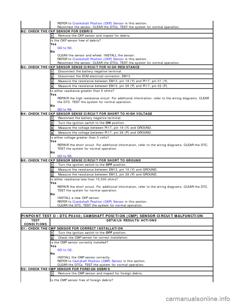
N
2: CHECK THE CKP SENSOR FOR DEBRIS
Re
move the CKP sensor
and inspect for debris.
1
Is the CKP sensor free of
debris?
Yes GO to N3
.
No
CLEAN the sensor and whee l. INSTALL the sensor.
REFER to Crankshaft Position (CKP) Sensor
in this section.
Reconnect the sensor. CLEAR the DTCs. TE ST the system for normal operation.
N
3: CHECK THE CKP SENSOR SENSE CIRCUIT FOR HIGH RESISTANCE
Di
sconnect the battery negative terminal.
1
D
isconnect the ECM electrical connector, EM13.
2
Me
asure the resistance between EM13, pin 19 (Y) and PI17, pin 01 (Y).
3
Meas
ure the resistance between EM13, pin 28 (P) and PI17, pin 02 (P).
4
Is either resi
stance
greater than 5 ohms?
Yes REPAIR the high resistance circui t. For additional information, refer to the wiring diagrams. CLEAR
the DTC. TEST the system for normal operation.
No GO to N4
.
N
4: CHECK THE CKP SENSOR SENSE CI
RCUIT FOR SHORT TO HIGH VOLTAGE
R
econnect the battery negative terminal.
1
Turn the ignition swi
tch to the ON
position.
2
Meas
ure the voltage between PI17, pin 19 (Y) and GROUND.
3
M
easure the voltage between PI17, pin 28 (P) and GROUND.
4
Is ei
ther voltage greater than 3 volts?
Yes REPAIR the short circuit. For addi tional information, refer to the wiring diagrams. CLEAR the DTC.
TEST the system for normal operation.
No GO to N5
.
N
5: CHECK THE CKP SENSOR SENSE CIRCUIT FOR SHORT TO GROUND
Turn the ignition swi
tch to the OFF
position.
1
Meas
ure the resistance between EM13, pin 19 (Y) and GROUND.
2
Meas
ure the resistance between EM13, pin 28 (P) and GROUND.
3
Is either resi
stance
less than 10,000 ohms?
Yes REPAIR the short circuit. For addi tional information, refer to the wiring diagrams. CLEAR the DTC.
TEST the system for normal operation.
No INSTALL a new CKP sensor.
REFER to Crankshaft Position (CKP) Sensor
in this section.
CLEAR the DTC. TEST the system for normal operation.
P
INPOINT TEST O : DTC P0340;
CAMSHAFT POSITION (CMP) SENSOR CIRCUIT MALFUNCTION
TE
ST
CONDITIONS
D
ETAILS/RESULTS/ACTIONS
O1: CHECK THE CM
P SENSOR FOR CORRECT INSTALLATION
Turn the ignition swi
tch to the OFF
position.
1
Check the CMP
sensor fo
r correct installation.
2
Is th
e CMP sensor correctly installed?
Yes GO to O2
.
No
INSTALL the CMP sensor correctly.
REFER to Camshaft Position (CMP) Sensor
in this section.
CLEAR the DTCs. TEST the system for normal operation.
O2: CHECK THE CM
P SENSOR FOR FOREIGN DEBRIS
Re
move the CMP sensor and
inspect for foreign debris.
1
Is the CMP sensor free of
foreign debris?
Page 1240 of 2490

In
stallation
7.
Re
move crankshaft position sensor.
R
e
move fixing.
Re
mo
ve sensor.
R
e
tain harness clips
1. Installation
is a reversal
of the removal procedure.