Crankshaft sensor JAGUAR X308 1998 2.G Workshop Manual
[x] Cancel search | Manufacturer: JAGUAR, Model Year: 1998, Model line: X308, Model: JAGUAR X308 1998 2.GPages: 2490, PDF Size: 69.81 MB
Page 15 of 2490

Superchar
ger
Outlet Pipe (18.50.16)
Supercharger Outlet Pipe Gasket (18.50.17)
Throttle Body Elbow (19.70.28)
Throttle Body Elbow Gasket (19.70.29)
303‐13: Evaporative Emissions
Diagnosis and Testing
Evaporative Emissions
Preliminary
Inspection
Diagnostic
Drive Cycles
Diagnostic
Trouble Code (DTC) index/Symptom Chart
Pinpoint
Tests
Removal
and Installation
Evaporative
Emission Canister (17.15.13)
Evaporative
Emission Canister Purge Valve (17.15.30)
Fuel
Tank Press
ure Sensor (19.55.31)
Fuel
Vapor Vent Valve Housing (19.55.24)
Fuel
Vapor Vent Valve Housing Seal (19.55.25)
303
‐14: Electronic Engine Controls
Description
and
Diagnosis
and Testing
Electronic
Engine Con
trols
Inspection
and Verification
Driver
Information Chart
Default
mode Definitions
Diagnostic
Trouble Code (DTC) Index
Pinpoint
Tests
Removal
and Installation
Catalyst
Monitor Sensor LH (18.30.81)
Catalyst
Monitor Sensor RH (18.30.80)
Heated Oxygen Sensor (HO2S) LH (18.30.79)
Heated Oxygen Sensor (HO2S) RH (18.30.78)
Camshaft
Position
Sen s
or
ECM
Position
Sensor
Crankshaft
Removal
Engine
Coolant Temperature
Sensor
Operation
Intake Air Temperature (IAT) Sensor (18.
30.52)
Page 43 of 2490
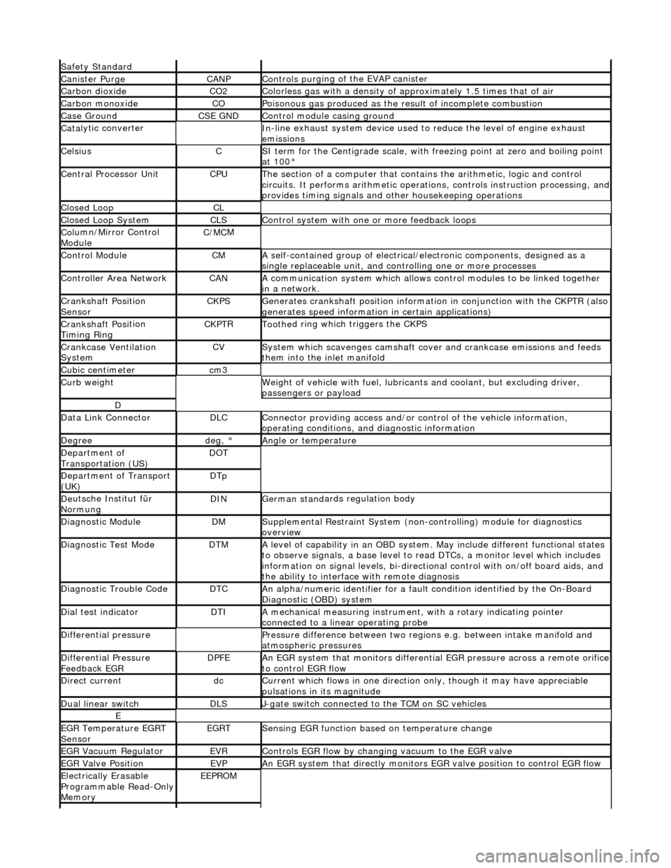
Safety Standard
Canister PurgeCANPControls pu
rging of the EVAP canister
Carbon dioxideCO2Colorless gas with
a density of a
pproximately 1.5 ti mes that of air
Carbon mon
oxide
COPoi
sonous gas produced as the re
sult of incomplete combustion
Case G
round
CSE GNDControl modu
le casing ground
Catal
ytic converter
In
-line exhaust system device used to reduce the level of engine exhaust
emissions
Ce
lsius
CSI ter
m for the Centigrade scale, with
freezing point at zero and boiling point
at 100°
Central
Processor Unit
CPUTh
e section of a computer that contai
ns the arithmetic, logic and control
circuits. It performs arithm etic operations, controls instruction processing, and
provides timing signals and other housekeeping operations
Cl
osed Loop
CL
Cl
osed Loop System
CLSControl
system with one
or more feedback loops
Col
umn/Mirror Control
Module
C/MC
M
Control ModuleCMA
self-contained group of electrical/electronic components, designed as a
single replaceable un it, and controlling one or more processes
Controll
er Area Network
CANA
communication system which allows control modules to be linked together
in a network.
Crankshaft Posi
tion
Sensor
CKPSGenerates crankshaft positi on informa
tion in conjunct
ion with the CKPTR (also
generates speed information in certain applications)
Crankshaft Posi
tion
Timing Ring
CKPT
R
Toothe
d ring which
triggers the CKPS
Crankcase Ventila
tion
System
CVSys
tem which scavenges camshaft cover and crankcase emissions and feeds
them into the inlet manifold
Cubic ce nt
imeter
cm
3
Curb weightWe
ight of vehicle with fuel, lubrican
ts and coolant, but excluding driver,
passengers or payload
D
Dat
a Link Connector
DLCConne
ctor providing access and/or control of the vehicle information,
operating conditions, and diagnostic information
De
gree
deg, °Angle or tempe
rature
D
epartment of
Transportation (US)
DO
T
D
epartment of Transport
(UK)
DTp
De
utsche In
stitut für
Normung
DINGerman stand
ards regulation body
Di
agnostic Module
DMSuppl
emental Restraint System (non-c
ontrolling) module for diagnostics
overview
Di
agnostic Test Mode
DTMA le
vel of capability in an OBD system.
May include different functional states
to observe signals, a base level to re ad DTCs, a monitor level which includes
information on signal levels, bi-directional control with on /off board aids, and
the ability to interface with remote diagnosis
Diagnostic Trouble CodeDTCAn al
pha/numeric identifier for a fault
condition identified by the On-Board
Diagnostic (OBD) system
D
ial test indicator
DTIA mechan
ical measuring
instrument, with a rotary indicating pointer
connected to a linear operating probe
D
ifferential pressure
Pressure di
fference betwee
n two regions e.g. between intake manifold and
atmospheric pressures
D
ifferential Pressure
Feedback EGR
DP
FE
An
EGR system that monito
rs differential EGR pressure across a remote orifice
to control EGR flow
D
irect current
dcCurrent which f
lows in on
e direction only, though it may have appreciable
pulsations in its magnitude
Du
al linear switch
DLSJ
-gate switch connected to the TCM on SC vehicles
E
EGR
Temperature EGRT
Sensor
EGRTSens
ing EGR function based on temperature change
EGR Vacu
um Regulator
EVRControls EGR
flow by changi
ng vacuum to the EGR valve
EGR Valve
Position
EVPAn EGR
system that direct
ly monitors EGR valve position to control EGR flow
Electrically E
rasable
Programmable Read-Only
Memory
EEP
ROM
Page 48 of 2490
Tacho
meter
TACHA
ci
rcuit that provides input for
an electronic tachometer display
Thermal Vacuu
m Valve
TVVControls vacuum l
e
vels or
routing based on temperature
Throttle
Body
TBDe
vi
ce containing the throttle
Throttl
e
Position
TP
Throttl
e
Position Sensor
TPSInterprets throttl
e
position and movement to iden tify idle, acceleration and
full-power demands
Top Dead CenterTDC
Torque Converter C
lutch
TCC
To
tal
indicator reading
TIRThe t
o
tal indicated movement on a DTI with the test piece rotated through
360°
Transm
ission Control
Module
TCMControls
the shifting pattern
of the (automatic) transmission
Transm
ission Control
Switch
TCSModifi es
the operation of electronically controlled transmissions
Transmission Oil
TemperatureTOTIndi
cat
es temperature of transmission fluid
Transmission RangeTRThe ran
g
e in which the transmission is operating
Transmission Spe
e
d
Sensor
TSSIndi cat
es rotational speed of transmission output shaft or turbine shaft
V
Vacuu
m
Solenoid Valve
VSVVacuu
m
operated valve used in the speed control system
Vacuu
m
Solenoid Valve
(atm)
VSV VAVacuu m
atmospheric valve used in the speed control system
Vacuu
m
Solenoid Valve
(rel)
VSV VRVacuu m
release valve used in the speed control system
Vacuu
m
Solenoid Valve
(vac)
VSV VVVacuu m
valve used in the speed control system
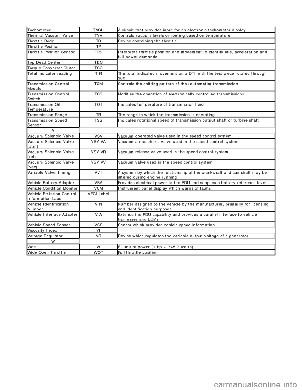
Variable Valve TimingVVTA
s
ystem by which the relationship of the crankshaft and camshaft may be
altered during engine running
Vehi cl
e Battery Adapter
VBAProvide
s
electrical power to the PDU
and supplies a battery reference level
Vehicl
e Condition Monitor
VCMInst
rum
ent panel display which warns of faults
Ve
hic
le Emission Control
Information Label
VECI Label
Vehi cl
e Identification
Number
VINN u
mber assigned to the vehicle by the manufacturer, primarily for licensing
and identification purposes
Vehi cl
e Interface Adapter
VIAExtends the
PDU ca
pability and provid
es a parallel interface to vehicle
harnesses and ECMs
Vehicle Spe e
d Sensor
VSSSens
or which provides ve
hicle speed information
Viscosity In
dexVI
Voltage RegulatorVRDe
vice which regulates the variable output voltage of a generator
W
Wat
tWSI unit of power (1 hp = 7
45.7 watts)
W
i
de Open Throttle
WO
TFu
ll throttle position
Page 528 of 2490
Speed an
d load
Coo
l
ant temperature
Ti
me el
apsed from start up
Cl
osed l
oop fuelling
Determination of the vapour concentration is made by stepped opening of the EVAP valve and subsequent monitoring of the
fuelling correction. This function is performed prior to purging, so that at the onse t of purging the EVAP valve can be set to
the optimum position. Should the ECM be unable to determine the concentration before purging, a default value is
employed, which is then modified whilst purging is in progress.
When the purging process is operational th e ECM modifies the basic fuelling calculation to maintain the correct air / fuel
ratio.
Purging is inhibited during fuel cut-off and stability / traction control intervention.
Coolant Temperature Sen
sor
Th
e
sensor outputs a voltage to the ECM which decreases as temperature increases.
Cooling Fans
In response to engi
ne coolant temperat
u
re and climate control system demand, the ECM will energize the cooling fans.
Climate Control Compressor
The E
C
M will allow the compressor clutch to be engaged if th
e engine temperature and load demand are normal. Should the
driver require maximum engine powe r or the coolant temperature be high, the request will be denied.
Cranking Signal
The ECM reacts to a signal fr
om th
e Body Processor Module (BPM) when the starter motor relay is energi
zed. This signal is
used to trigger starting, fu el and ignition strategies.
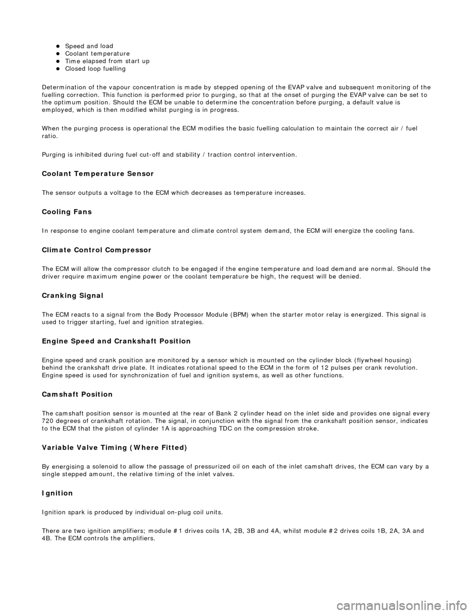
Engine Speed and Cranksh
aft Position
Engine
speed and cran
k position are moni
tored by a sensor which is mounted on the cylinder block (flywheel housing)
behind the crankshaft drive plat e. It indicates rotational speed to the ECM in the form of 12 pulses per crank revolution.
Engine speed is used for synchronization of fuel an d ignition systems, as well as other functions.
Camshaft Position
The ca
mshaft position sensor is mounted at
the rear of Bank 2 cylinder head on the inlet side and provides one signal every
720 degrees of crankshaft rotation. The signal, in conjunction with the signal from the crankshaft position sensor, indicates
to the ECM that the piston of cylinder 1A is approaching TDC on the compression stroke.
Variable Valve
Timing (Where Fitted)
By energi
si
ng a solenoid to allow the pass
age of pressurized oil on each of the inle t camshaft drives, the ECM can vary by a
single stepped amount, the relati ve timing of the inlet valves.
Ign
ition
Ignit
i
on spark is produced by
individual on-plug coil units.
There are two ignition amplifiers; module #1 drives coils 1A, 2B, 3B and 4A, whilst module #2 drives coils 1B, 2A, 3A and
4B. The ECM controls the amplifiers.
Page 531 of 2490
En
gine - Engine
D
iagnosis and Testing
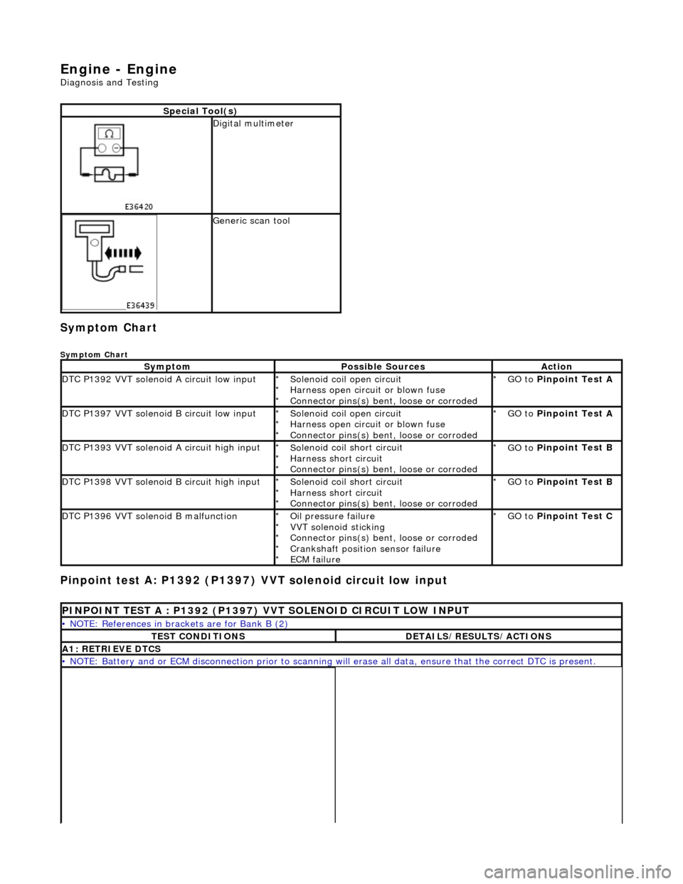
Sym
ptom Chart
Sy
mptom Chart
Pinp
oint test A: P1392 (P1397)
VVT solenoid circuit low input
S
pecial Tool(s)
D
igital multimeter
Generi
c scan tool
Sy
mptom
Possib
le Sources
Acti
on
D
TC P1392 VVT solenoid A circuit low input
So
lenoid coil open circuit
Harness open circuit or blown fuse
Connector pins(s) bent , loose or corroded
*
*
*
GO to
P
inpoint Test A
*
D
TC P1397 VVT solenoid B circuit low input
So
lenoid coil open circuit
Harness open circuit or blown fuse
Connector pins(s) bent , loose or corroded
*
*
*
GO to
P
inpoint Test A
*
D
TC P1393 VVT solenoid A circuit high input
So
lenoid coil short circuit
Harness short circuit
Connector pins(s) bent , loose or corroded
*
*
*
GO to
P
inpoint Test B
*
D
TC P1398 VVT solenoid B circuit high input
So
lenoid coil short circuit
Harness short circuit
Connector pins(s) bent , loose or corroded
*
*
*
GO to
P
inpoint Test B
*
D
TC P1396 VVT solenoid B malfunction
O
il pressure failure
VVT solenoid sticking
Connector pins(s) bent , loose or corroded
Crankshaft position sensor failure
ECM failure
*
*
*
*
*
GO to
P
inpoint Test C
*
P
INPOINT TEST A : P1392 (P1397) VVT SOLENOID CIRCUIT LOW INPUT
•
NOTE: References in brac
kets are for Bank B (2)
T
EST CONDITIONS
D
ETAILS/RESULTS/ACTIONS
A1
: RETRIEVE DTCS
•
NOTE: Battery and or ECM disconnection prior to scanning wi
ll erase all data, ensure that the correct DTC is present.
Page 566 of 2490
2.
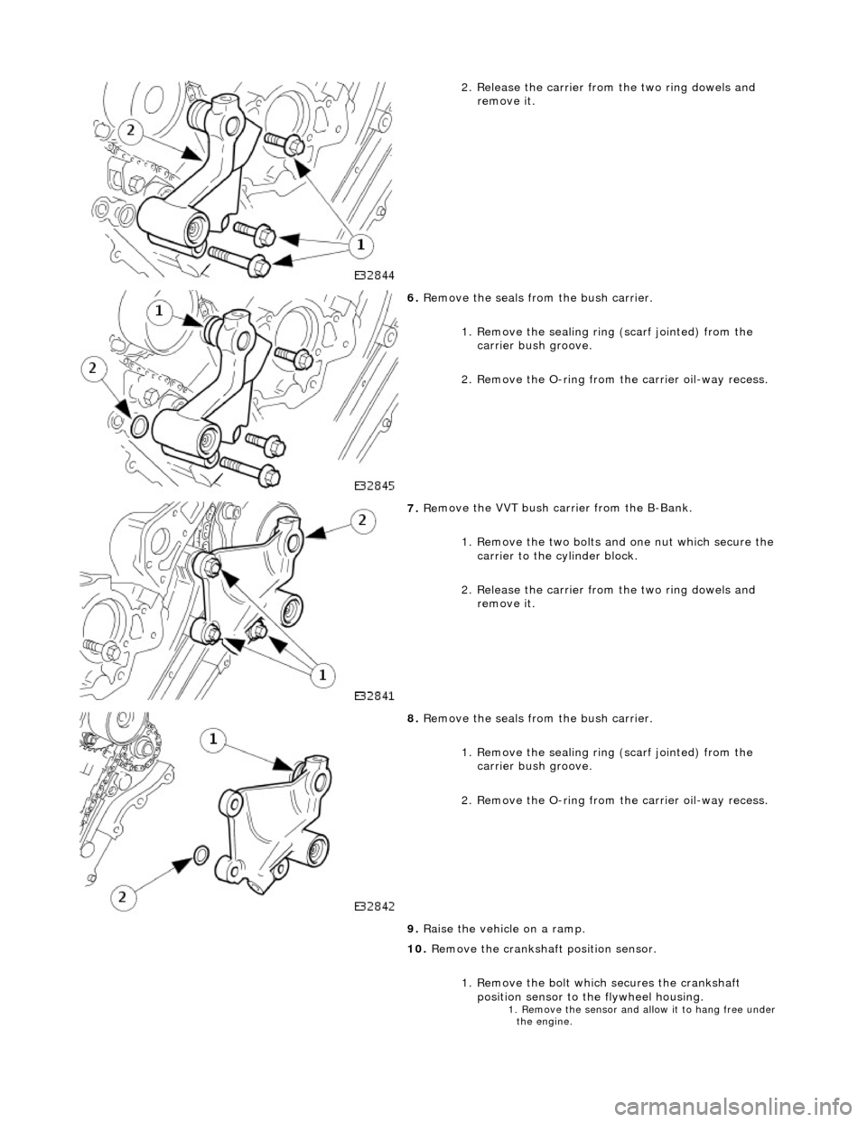
Release the carrier from
the two ring dowels and
remove it.
6. Re
move the seals from the bush carrier.
1. Remove the sealing ring (scarf jointed) from the
carrier bush groove.
2. Remove the O-ring from the carrier oil-way recess.
7. Re
move the VVT bush carrier from the B-Bank.
1. Remove the two bolts and one nut which secure the carrier to the cylinder block.
2. Release the carrier from the two ring dowels and
remove it.
8. Re
move the seals from the bush carrier.
1. Remove the sealing ring (scarf jointed) from the
carrier bush groove.
2. Remove the O-ring from the carrier oil-way recess.
9. Raise the vehicle on a ramp.
10. Remove the crankshaft position sensor.
1. Remove the bolt which secures the crankshaft position sensor to the flywheel housing.
1. Re move
the sensor and allow it to hang free under
the engine.
Page 567 of 2490
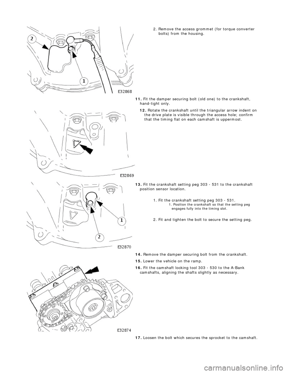
2
. Remove the access grommet (for torque converter
bolts) from the housing.
11. Fit the damper securing bolt (old one) to the crankshaft,
hand-tight only.
12
.
Rotate the crankshaft until the triangular arrow indent on
the drive plate is visible thro ugh the access hole; confirm
that the timing flat on ea ch camshaft is uppermost.
13
.
Fit the crankshaft setting peg 303 - 531 to the crankshaft
position sensor location.
1. Fit the crankshaft setting peg 303 - 531.
1. P
osition the crankshaft so that the setting peg
engages fully into the timing slot.
2
. Fit and tighten the bolt to secure the setting peg.
14. Remove the damper securing bolt from the crankshaft.
15. Lower the vehicle on the ramp.
16
.
Fit the camshaft locking tool 303 - 530 to the A-Bank
camshafts, aligning the shafts slightly as necessary.
17. Loosen the bolt which secures the sprocket to the camshaft.
Page 574 of 2490
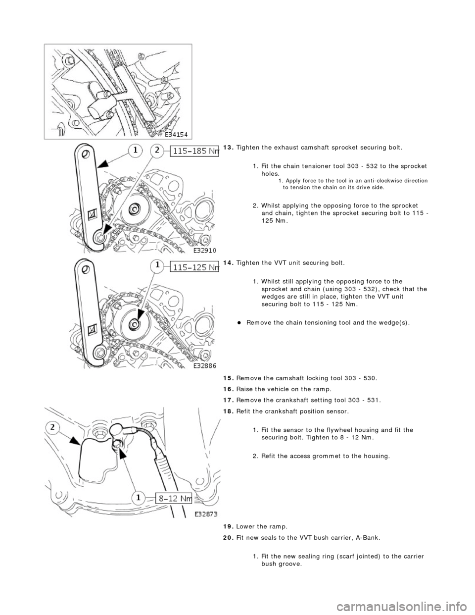
13. Tigh
ten the exhaust camshaft
sprocket securing bolt.
1. Fit the chain tensioner tool 303 - 532 to the sprocket holes.
1. Apply force to the to
ol in
an anti-clockwise direction
to tension the chain on its drive side.
2 .
Whilst applying the opposing force to the sprocket
and chain, tighten the sprock et securing bolt to 115 -
125 Nm.
14 . Tigh
ten the VVT unit securing bolt.
1. Whilst still applying the opposing force to the
sprocket and chain (using 303 - 532), check that the
wedges are still in place, tighten the VVT unit
securing bolt to 115 - 125 Nm.
R e
move the chain tensioning
tool and the wedge(s).
15. Remove the camshaft locking tool 303 - 530.
16. Raise the vehicle on the ramp.
17. Remove the crankshaft setting tool 303 - 531.
18 . R
efit the crankshaft position sensor.
1. Fit the sensor to the fl ywheel housing and fit the
securing bolt. Tighten to 8 - 12 Nm.
2. Refit the access grommet to the housing.
19. Lower the ramp.
20. Fit new seals to the VVT bush carrier, A-Bank.
1. Fit the new sealing ring ( scarf jointed) to the carrier
bush groove.
Page 576 of 2490
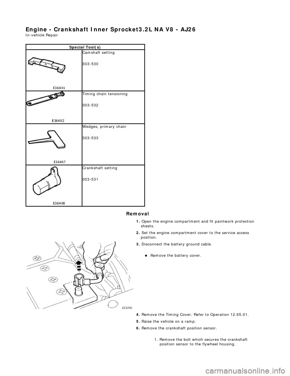
Engine - Crankshaft Inner Sprocket3.2L NA V8 - AJ26
In-vehic
le Repair
Remov
a
l
S
p
ecial Tool(s)
Camshaft setting
3
03-
530
T
i
ming chain tensioning
303-532
Wedges, primary ch ain
303-533
Cranksha
ft setting
303-531
1. Open the engine compartment and fit paintwork protection
sheets.
2. Set the engine compartment cover to the service access
position.
3. Disc
onnect the batt
ery ground cable.
Re
move the battery cover.
4. Remove the Timing Cover. Re fer to Operation 12.65.01.
5. Raise the vehicle on a ramp.
6. Remove the crankshaft position sensor.
1. Remove the bolt which secures the crankshaft position sensor to the flywheel housing.
Page 577 of 2490
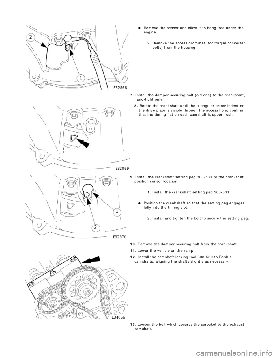
Remove the
sensor and allow
it to hang free under the
engine.
2. Remove the access grommet (for torque converter bolts) from the housing.
7. Install the damper securing bolt (old one) to the crankshaft,
hand-tight only.
8. R
otate the crankshaft until the triangular arrow indent on
the drive plate is visible thro ugh the access hole; confirm
that the timing flat on ea ch camshaft is uppermost.
9. Inst
all the crankshaft setting peg 303-531 to the crankshaft
position sensor location.
1. Install the crankshaft setting peg 303-531.
Position the crankshaft so that the settin
g peg engages
fully into the timing slot.
2. Install and tighten the bolt to secure the setting peg.
10. Remove the damper securing bolt from the crankshaft.
11. Lower the vehicle on the ramp.
12
.
Install the camshaft locking tool 303-530 to Bank 1
camshafts, aligning the shafts slightly as necessary.
13. Loosen the bolt which secures the sprocket to the exhaust
camshaft.