Connector JAGUAR X308 1998 2.G Manual Online
[x] Cancel search | Manufacturer: JAGUAR, Model Year: 1998, Model line: X308, Model: JAGUAR X308 1998 2.GPages: 2490, PDF Size: 69.81 MB
Page 547 of 2490
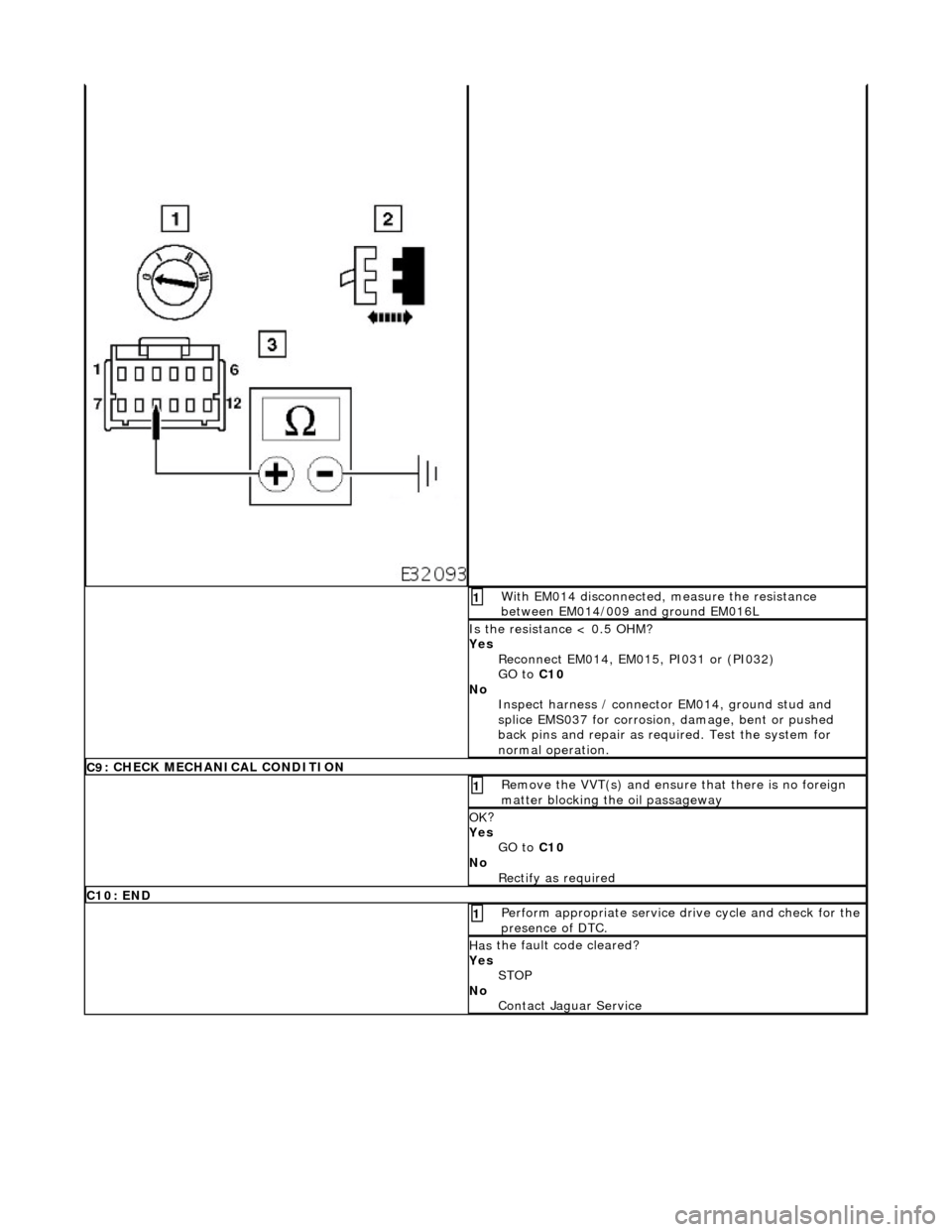
W
ith EM014 disconnected, measure the resistance
between EM014/009 and ground EM016L
1
I
s the resistance < 0.5 OHM?
Yes Reconnect EM014, EM015, PI031 or (PI032)
GO to C10
No Inspect harness / connector EM014, ground stud and
splice EMS037 for corrosion, damage, bent or pushed
back pins and repair as required. Test the system for
normal operation.
C9
: CHECK MECHANICAL CONDITION
R
emove the VVT(s) and ensure
that there is no foreign
matter blocking the oil passageway
1
OK
?
Yes GO to C10
No Rectify as required
C
10: END
Perform
appropriate service drive cycle and check for the
presence of DTC.
1
Has
the fault code cleared?
Yes STOP
No Contact Jaguar Service
Page 704 of 2490
Engine - Intake Manifol
d
In-v
ehic
le Repair
Remov
a
l
W
A
RNING: BEFORE PROCEEDING, IT IS ESSENTIAL THAT
THE WARNINGS GIVEN IN SECTION 100-00 (UNDER THE
HEADING 'SAFETY PRECAUTIONS') ARE READ AND UNDERSTOOD.
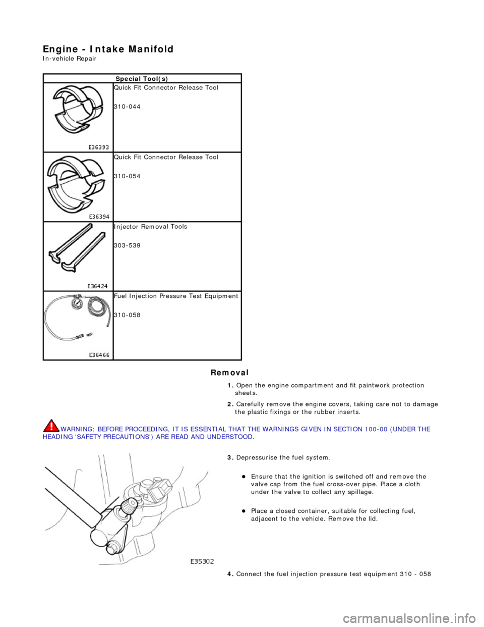
S p
ecial Tool(s)
Qu
ic
k Fit Connector Release Tool
310-044
Qu ic
k Fit Connector Release Tool
310-054
Inject or Remov
al Tools
303-539
F u
el Injection Pressu
re Test Equipment
310-058
1. Open the engine compartment and fit paintwork protection
sheets.
2. Carefully remove the en gine covers, taking care not to damage
the plastic fixings or the rubber inserts.
3. Depress
urise the fuel system.
пЃ¬E
n
sure that the ignition is
switched off and remove the
valve cap from the fuel cross-over pipe. Place a cloth
under the valve to collect any spillage.
пЃ¬Pla c
e a closed container, su
itable for collecting fuel,
adjacent to the vehicle. Remove the lid.
4. Connect the fuel injection pres sure test equipment 310 - 058
Page 708 of 2490
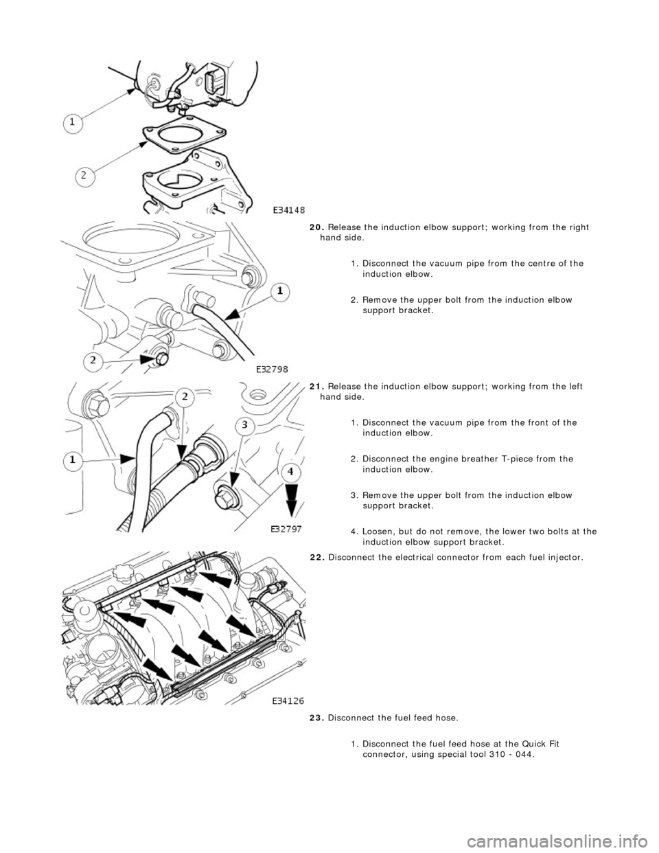
20. Release the induction elbow su pport; working from the right
hand side.
1. Disconnect the vacuum pi pe from the centre of the
induction elbow.
2. Remove the upper bolt from the induction elbow support bracket.
21. Release the induction elbow su pport; working from the left
hand side.
1. Disconnect the vacuum pipe from the front of the
induction elbow.
2. Disconnect the engine breather T-piece from the induction elbow.
3. Remove the upper bolt from the induction elbow support bracket.
4. Loosen, but do not remove , the lower two bolts at the
induction elbow support bracket.
22. Disconnect the electrical conne ctor from each fuel injector.
23. Disconnect the fuel feed hose.
1. Disconnect the fuel f eed hose at the Quick Fit
connector, using special tool 310 - 044.
Page 709 of 2490

24. Disconnect the fuel return hose.
1. Disconnect the fuel retu rn hose at the Quick Fit
connector, using special tool 310 - 054.
25. Remove the inlet manifold.
1. Remove the ten bolts which secure the inlet manifold.
2. Remove the inlet manifold
26. Remove and discard the eight se als from the inlet manifold
ports.
27. Remove the fuel pressure regulator from the manifold.
1. Remove the two bolts which secure the pressure regulator.
2. Remove the pressure regulator.
Page 713 of 2490

elbow.
8. Refit the Manifold Assembly to the Engine, as follows.
9. Fit eight new seals to the inlet manifold ports.
10. Fit the inlet manifold to the engine.
1. Fit the inlet manifold.
2. Fit the ten bolts which secure the inlet manifold.
11. Connect the fuel feed hose.
1. Connect the fuel feed hose at the Quick Fit connector. Ensure that the hose is fully seated to the feed pipe.
12. Connect the fuel return hose.
1. Connect the fuel return hose at the Quick Fit
connector. Ensure th at the hose is fully seated to the
feed pipe.
Page 714 of 2490
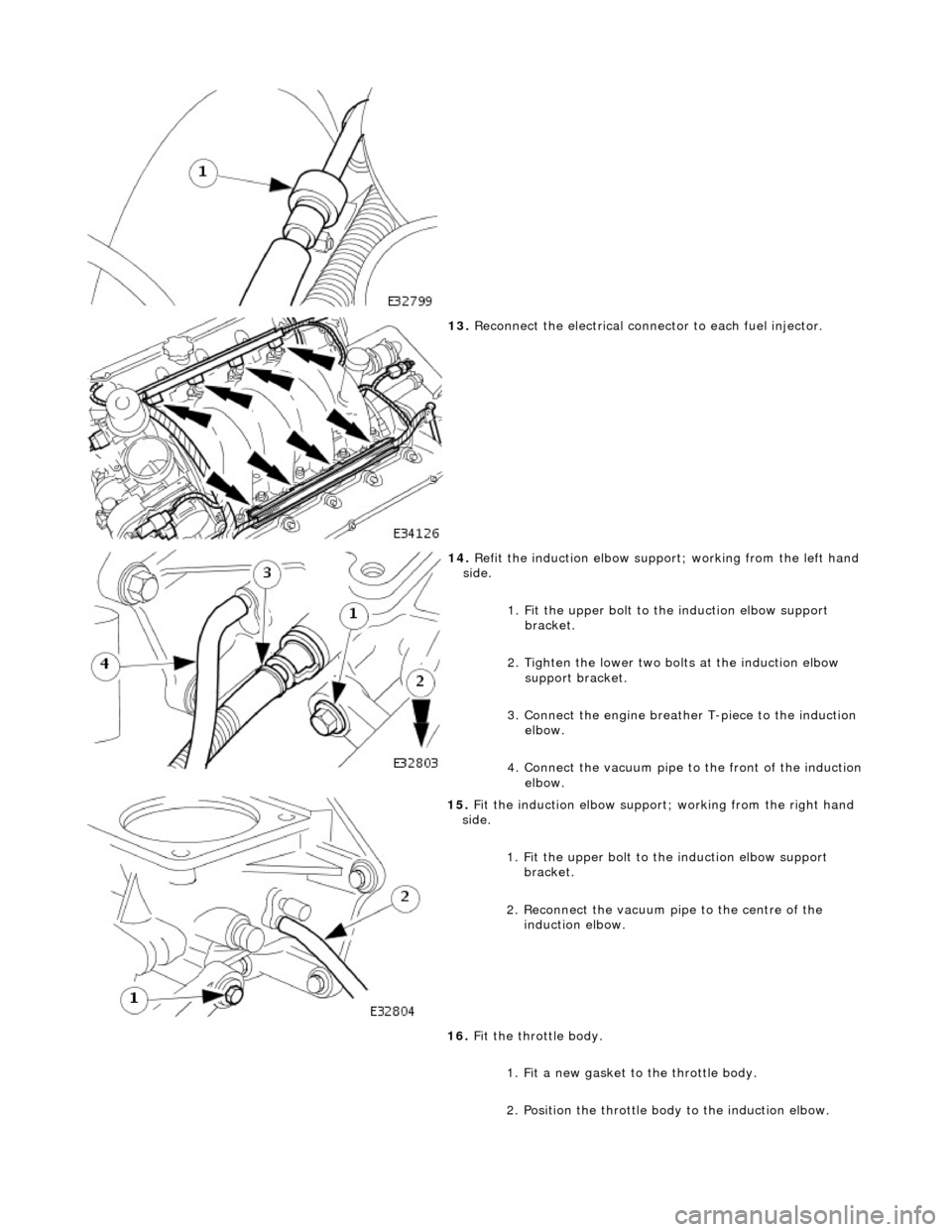
13. Reconnect the electrical connector to each fuel injector.
14. Refit the induction elbow support ; working from the left hand
side.
1. Fit the upper bolt to the induction elbow support
bracket.
2. Tighten the lower two bolts at the induction elbow support bracket.
3. Connect the engine breather T-piece to the induction elbow.
4. Connect the vacuum pipe to the front of the induction
elbow.
15. Fit the induction elbow support; working from the right hand
side.
1. Fit the upper bolt to the induction elbow support
bracket.
2. Reconnect the vacuum pi pe to the centre of the
induction elbow.
16. Fit the throttle body.
1. Fit a new gasket to the throttle body.
2. Position the throttle body to the induction elbow.
Page 718 of 2490
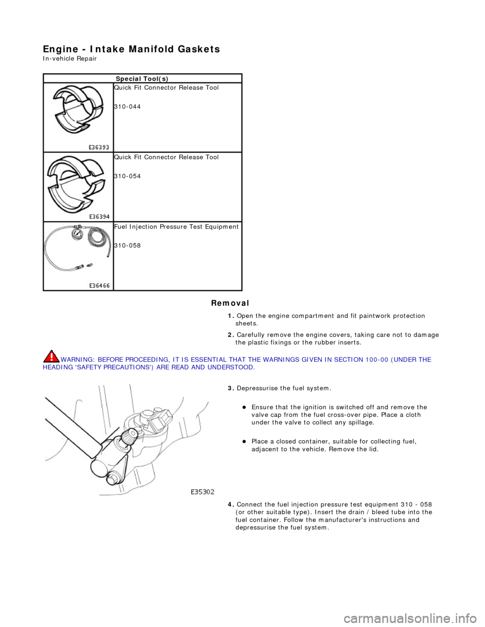
Engine - Intake Manifold Gaskets
In-vehicle Repair
Removal
WARNING: BEFORE PROCEEDING, IT IS ESSENTIAL THAT THE WARNINGS GIVEN IN SECTION 100-00 (UNDER THE
HEADING 'SAFETY PRECAUTIONS') ARE READ AND UNDERSTOOD.
Special Tool(s)
Quick Fit Connector Release Tool
310-044
Quick Fit Connector Release Tool
310-054
Fuel Injection Pressu re Test Equipment
310-058
1. Open the engine compartment and fit paintwork protection
sheets.
2. Carefully remove the en gine covers, taking care not to damage
the plastic fixings or the rubber inserts.
3. Depressurise the fuel system.
пЃ¬Ensure that the ignition is switched off and remove the
valve cap from the fuel cross-over pipe. Place a cloth
under the valve to collect any spillage.
пЃ¬Place a closed container, su itable for collecting fuel,
adjacent to the vehicle. Remove the lid.
4. Connect the fuel injection pres sure test equipment 310 - 058
(or other suitable type). Insert the drain / bleed tube into the
fuel container. Follow the ma nufacturer's instructions and
depressurise the fuel system.
Page 722 of 2490
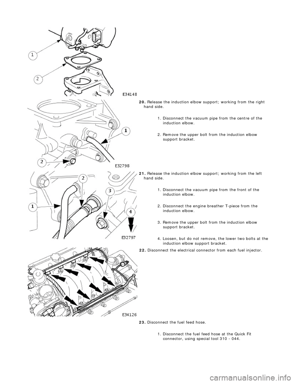
20. Release the induction elbow su pport; working from the right
hand side.
1. Disconnect the vacuum pi pe from the centre of the
induction elbow.
2. Remove the upper bolt from the induction elbow support bracket.
21. Release the induction elbow su pport; working from the left
hand side.
1. Disconnect the vacuum pipe from the front of the
induction elbow.
2. Disconnect the engine breather T-piece from the induction elbow.
3. Remove the upper bolt from the induction elbow support bracket.
4. Loosen, but do not remove , the lower two bolts at the
induction elbow support bracket.
22. Disconnect the electrical conne ctor from each fuel injector.
23. Disconnect the fuel feed hose.
1. Disconnect the fuel f eed hose at the Quick Fit
connector, using special tool 310 - 044.
Page 723 of 2490

Installation
24. Disconnect the fuel return hose.
1. Disconnect the fuel retu rn hose at the Quick Fit
connector, using special tool 310 - 054.
25. Remove the inlet manifold.
1. Remove the ten bolts which secure the inlet manifold.
2. Remove the inlet manifold
26. Remove and discard the eight se als from the inlet manifold
ports.
1. Clean all parts and relevant mating faces.
2. Fit eight new seals to the inlet manifold ports.
Page 724 of 2490
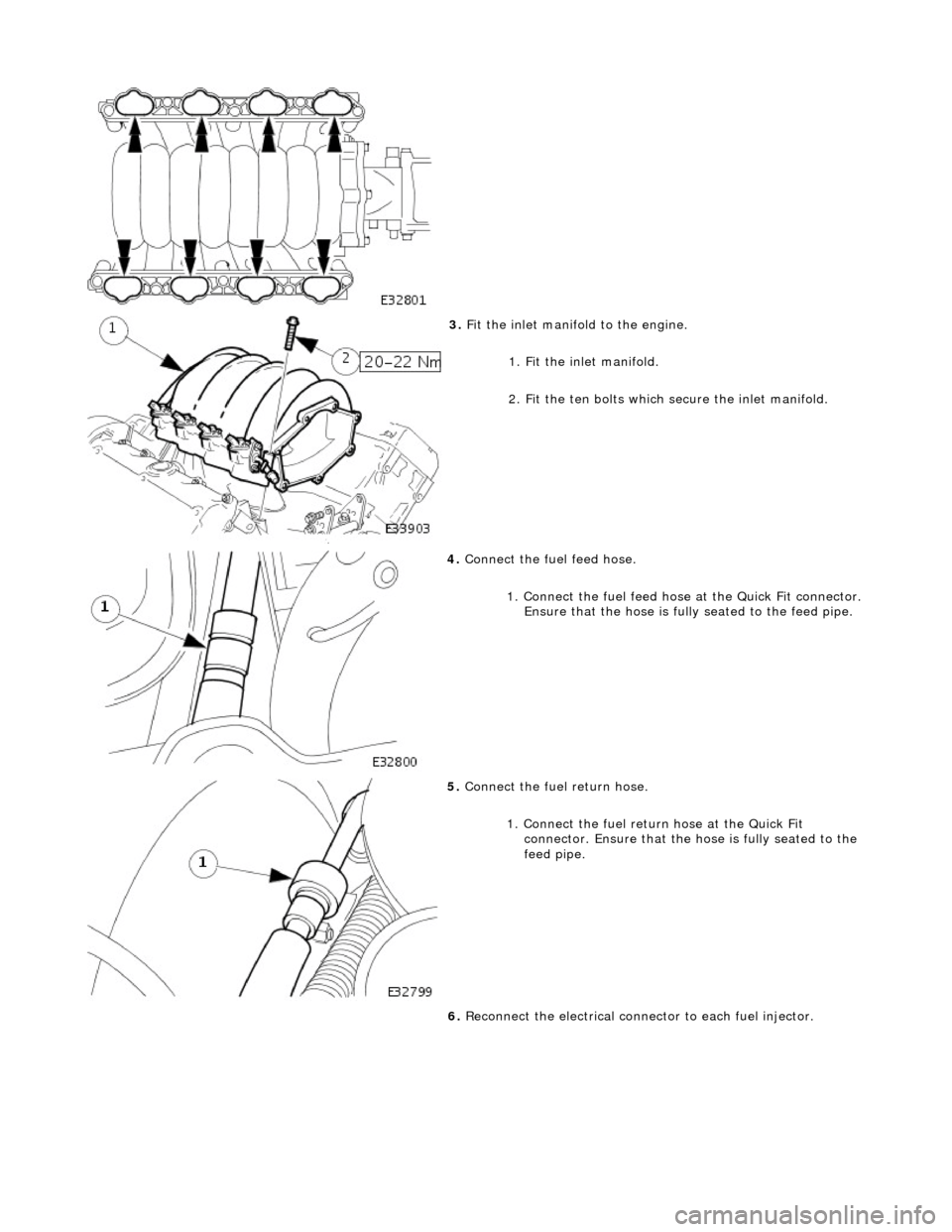
3. Fit the inlet manifold to the engine.
1. Fit the inlet manifold.
2. Fit the ten bolts which secure the inlet manifold.
4. Connect the fuel feed hose.
1. Connect the fuel feed hose at the Quick Fit connector. Ensure that the hose is fully seated to the feed pipe.
5. Connect the fuel return hose.
1. Connect the fuel return hose at the Quick Fit
connector. Ensure th at the hose is fully seated to the
feed pipe.
6. Reconnect the electrical connector to each fuel injector.