Connector JAGUAR X308 1998 2.G Repair Manual
[x] Cancel search | Manufacturer: JAGUAR, Model Year: 1998, Model line: X308, Model: JAGUAR X308 1998 2.GPages: 2490, PDF Size: 69.81 MB
Page 487 of 2490

m
ember. The quick-fit connector O-rings are not serviceable.
Special tool JD 182 is required to disconnect the quick-fit connector.
Hydraulic System
P
arts List
Hydraulic System
Op
erating Principle
The rot
ary motion of the steering wheel is converted, via the st
eering rack pinion, to the lateral motion of the rack. Steering
assistance is provided by pressurized fluid being directed against a piston operating within the rack cylinder. Rack
movement is achieved by diffe rential pressures being applied on either si de of the rack piston, caused by unequal
restrictions within the hydraulic control valve.
The main components of the hydraulic control valve are the rota ry distributor, control sleeve and hydraulic reaction piston.
It
em
Par
t Number
De
scription
1—F
luid reservoir
2—Pum
p
3—Pressure and fl
ow limiting valve
4—Supply line
5—R
eturn line
6—Steeri
ng rack
7—Pin
ion
8—O
perating cylinder and piston
9—Hydrau
lic control valve
10—Hydraulic reaction
piston
11—Control
sleeve
12—R
otary distributor
13—F
luid cooler
A
quick-fit connector with double O-ring se
als is incorporated in the return line and is clipped to the right-hand chassis side
Page 490 of 2490
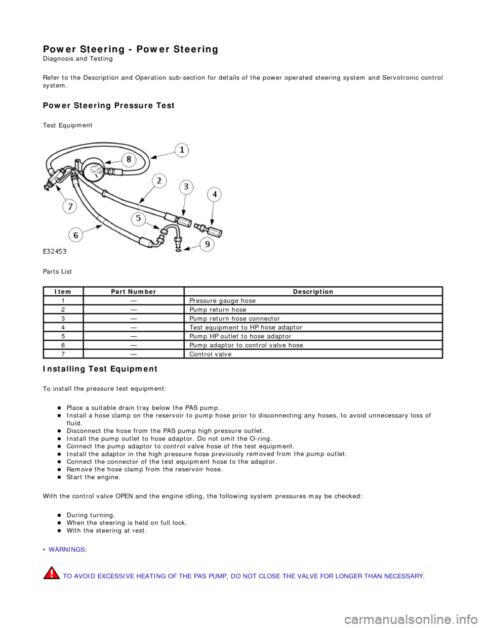
Power Steering - Power Steering
Diagn
osis and Testing
Refer to the Description and Operation sub-section for details of the power operated steering system and Servotronic control
system.
Power Steer ing Pressure Test
Test Equ
i
pment
Parts List
In
stalling Test Equipment
To
in
stall the pressure test equipment:
пЃ¬Pla
c
e a suitable drain tray below the PAS pump.
пЃ¬Install a hose clamp
on
the re
servoir to pump hose prior to disconnecting any hoses, to avoid unnecessary loss of
fluid.
пЃ¬Di sc
onnect the hose from the PAS pump high pres
sure outlet.
пЃ¬Ins
tall the pump outlet to hose ad
aptor. Do not omit the O-ring.
пЃ¬Conn
ect the pump adaptor to control valve hose of the test equipment.
пЃ¬Install th
e adaptor in the high pressure hose previ
ously re
moved from the pump outlet.
пЃ¬Conne
ct the connector of the test equipment hose to the adaptor.
пЃ¬R
e
move the hose clamp fro
m the reservoir hose.
пЃ¬Start th
e engine.
With the control valve OPEN and the engine idling , the following system pressures may be checked:
пЃ¬Du
ring turning.
пЃ¬W
h
en the steering is
held on full lock.
пЃ¬With
the steeri
ng at rest.
• WARNINGS:
TO AVOID EXCESSIVE HEATING OF THE PAS PUMP, DO NOT CLOSE THE VALVE FOR LONGER THAN NECESSARY.
Ite
m
Par
t
Number
De
scr
iption
1—Pressure
gauge hose
2—Pump return hose
3—Pump return hose connector
4—Test equi
pment to
HP hose adaptor
5—Pump HP outlet to hose adaptor
6—Pump adaptor
to control valve hose
7—Control valve
Page 493 of 2490

Righ
t-hand drive vehicles
All vehicles
7. De
tach the steering
column lower shaft.
1. Loosen the steering column lower shaft retaining bolt.
2. Remove and discard the st eering column lower shaft
retaining bolt.
3. Detach the steering column lower shaft.
8. Di
sconnect the steering gear transducer electrical connector.
9. Cut an
d discard the stee
ring gear transducer harness tie-strap.
10
.
Cut and discard the power steeri ng return pipe tie-strap.
11. Detach the power steering re turn pipe from the mounting
rubber.
Page 494 of 2490
In
stallation
All vehicles
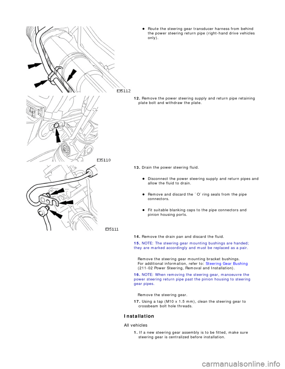
пЃ¬Route t
he steering gear transducer harness from behind
the power steering return pipe (right-hand drive vehicles
only).
12 . Remove the
power steering supply and return pipe retaining
plate bolt and with draw the plate.
13 . D
rain the power steering fluid.
пЃ¬Di
sc
onnect the power steering
supply and return pipes and
allow the fluid to drain.
пЃ¬Remove an d discard the ВґOВґring seals from the
pipe
connectors.
пЃ¬Fi t su
itable blanking caps
to the pipe connectors and
pinion housing ports.
14. Remove the drain pan and discard the fluid.
15. NOTE: The steering gear mounting bushings are handed;
they are marked accordingly and must be replaced as a pair.
Remove the steering gear mo unting bracket bushings.
For additional information, refer to: Steering Gear Bushing
( 21
1-02 Power Steering, Removal and Installation).
16. NOTE: When removing the steering gear, manoeuvre the
power steering return pipe past the pinion housing to steering
gear pipes.
Remove the steering gear.
17. Using a tap (M10 x 1.5 mm), clean the steering gear to
crossbeam bolt hole threads.
1. If a new steering gear assembly is to be fitted, make sure
steering gear is centrali zed before installation.
Page 495 of 2490
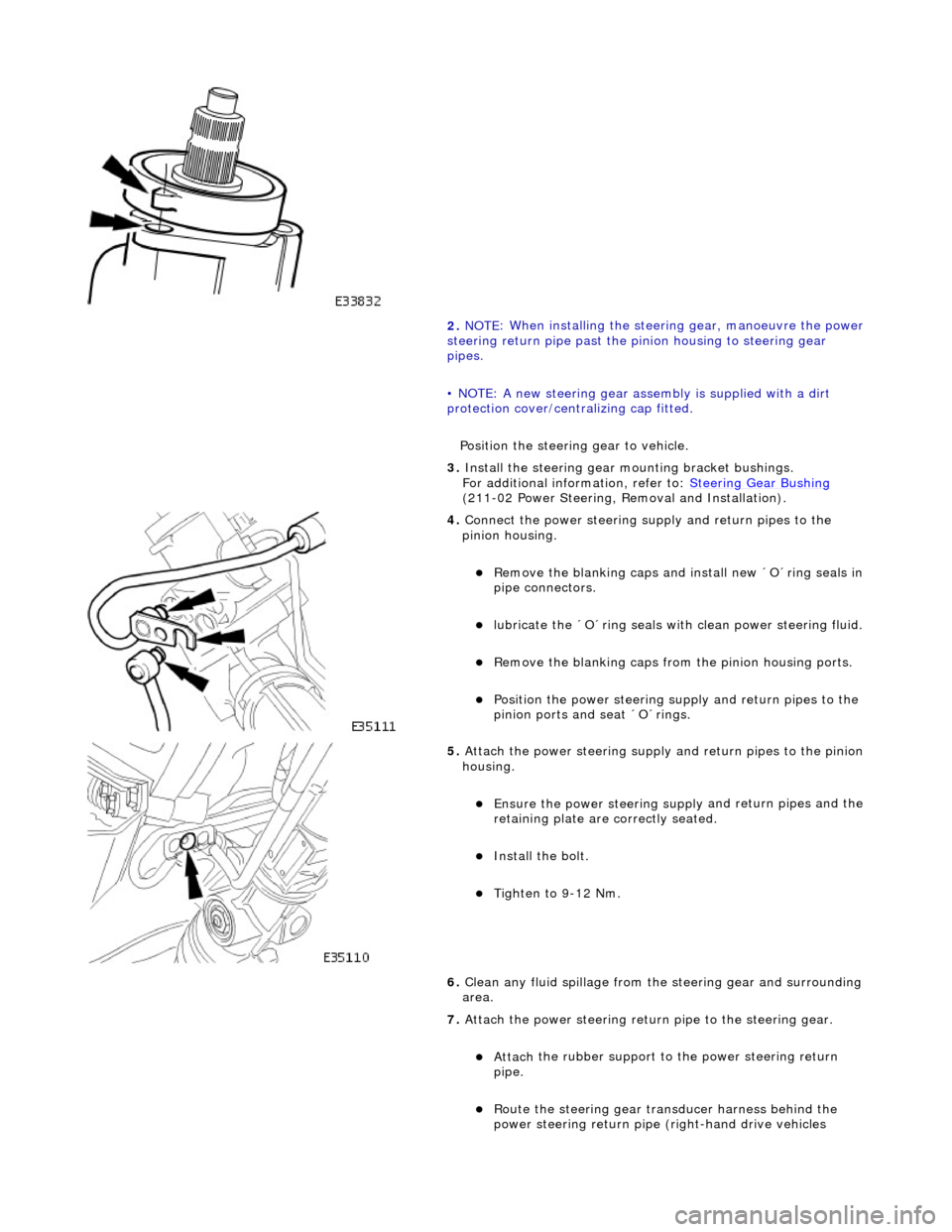
2. NOTE
: When installing the steering gear, manoeuvre the power
steering return pipe past the pinion housin g to steering gear
pipes.
• NOTE: A new steering gear assembly is supplied with a dirt
protection cover/cent ralizing cap fitted.
Position the steering gear to vehicle.
3. Install the steering gear mo unting bracket bushings.
For additional information, refer to: Steering Gear Bushing
(
211-02 Power Steering, Removal and Installation).
4. Conne
ct the power steering su
pply and return pipes to the
pinion housing.
пЃ¬R
emove the blanking caps an
d install new ВґOВґring seals in
pipe connectors.
пЃ¬lubri
cate the ВґOВґring seals wi
th clean power steering fluid.
пЃ¬R
emove the blanking caps from
the pinion housing ports.
пЃ¬Position the power
steering su
pply and return pipes to the
pinion ports and seat ВґOВґrings.
5. Attach
the power steering supply
and return pipes to the pinion
housing.
пЃ¬Ensure the power steering su pply
and return pipes and the
retaining plate are correctly seated.
пЃ¬Install th
e bolt.
пЃ¬Tigh
ten to 9-12 Nm.
6. Clean any fluid spillage from the steering gear and surrounding
area.
7. Attach the power steering return pipe to the steering gear.
пЃ¬Attach
the rubber support to
the power steering return
pipe.
пЃ¬Rout
e the steering gear transducer harness behind the
power steering return pipe (right-hand drive vehicles
Page 496 of 2490

Right
-hand drive vehicles
All vehicles
only
).
8. Install a new power st ee
ring return
pipe tie-strap.
9. Install a new steering gear transducer harness tie-strap.
10 . Conne
ct the steering gear transducer electrical connector.
пЃ¬On righ
t-hand drive vehicles
, position the steering gear
transducer harness behind th e power steering return pipe.
11
. NOTE
: Right-hand shown, left-hand similar.
Attach the tie rod end.
Page 509 of 2490
пЃ¬Is adjustable for both til
t and reach.
пЃ¬Has ca
ble operated reach adjustment, using a rack an
d wedge, with approximately 16 latched positions.
пЃ¬Has si
x latched tilt positions steppe
d at approximately 3В° intervals.
пЃ¬Has an u
nlatched top tilt position, allowing the column to be
pulled down to engage the first detent without using the
tilt lever.
пЃ¬Has an instrument li
ghti
ng dimmer switch installed on the left-hand side of the lower cowl.
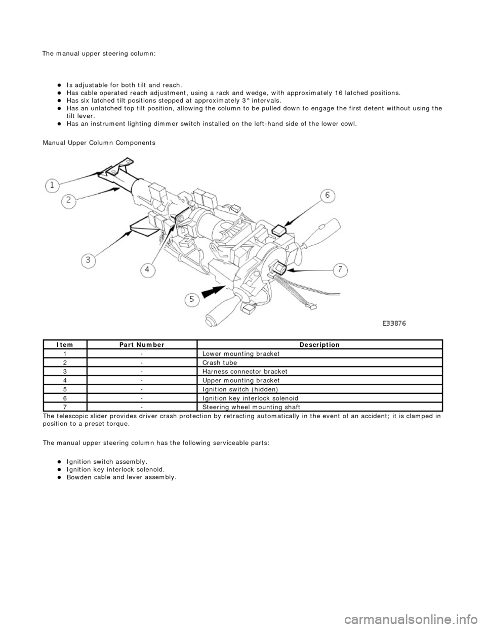
Manual Upper Column Components
The telescopic slider provides driver crash protection by retracting automatically in the event of an accident; it is clamped in
position to a preset torque.
The manual upper steering column has the following serviceable parts:
пЃ¬Igni
tion switch assembly.
пЃ¬Igni
tion key interlock solenoid.
пЃ¬Bowden
cable and lever assembly.
It
em
Par
t Number
De
scription
1-L
ower mounting bracket
2-Crash tube
3-Harnes
s connector bracket
4-Upper
mounting bracket
5-Ignition switc
h (hidden)
6-Igni
tion key interlock solenoid
7-S
teering wheel mounting shaft
The manu
al upper
steering column:
Page 519 of 2490
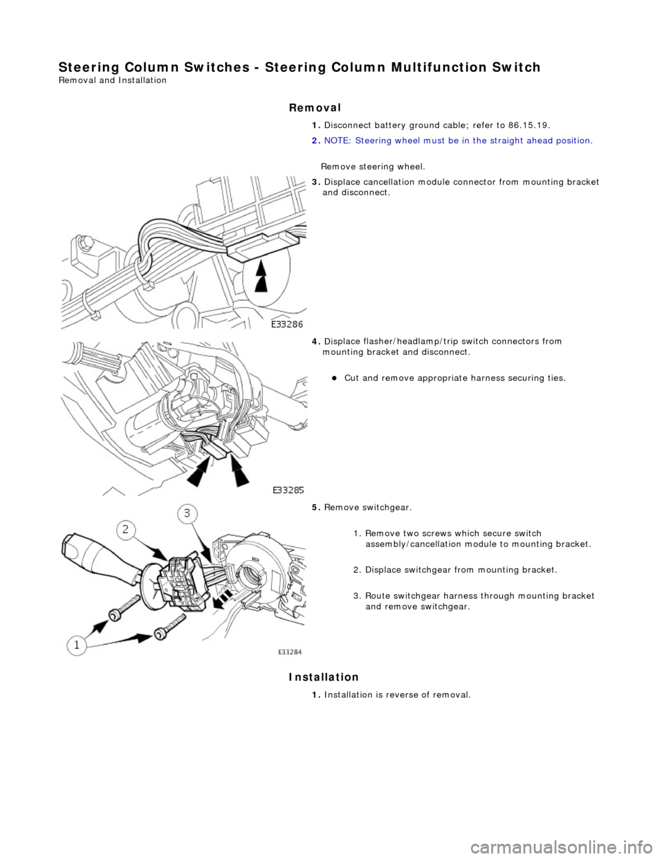
Steering Column Switches - Steering Colu
mn Multifunction Switch
Re
moval and Installation
Remov
al
Installation
1.
D
isconnect battery ground cable; refer to 86.15.19.
2. NOTE: Steering wheel must be in the straight ahead position.
Remove steering wheel.
3. Di
splace cancellation module connector from mounting bracket
and disconnect.
4. Di
splace flasher/headlamp/t
rip switch connectors from
mounting bracket and disconnect.
пЃ¬Cut an
d remove appropriate harness securing ties.
5. Re
move switchgear.
1. Remove two screws which secure switch assembly/cancellation module to mounting bracket.
2. Displace switchgear from mounting bracket.
3. Route switchgear harness through mounting bracket and remove switchgear.
1. Installation is reverse of removal.
Page 531 of 2490
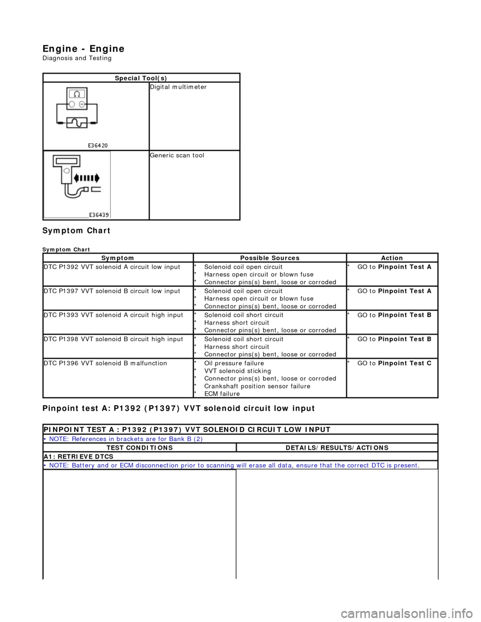
En
gine - Engine
D
iagnosis and Testing
Sym
ptom Chart
Sy
mptom Chart
Pinp
oint test A: P1392 (P1397)
VVT solenoid circuit low input
S
pecial Tool(s)
D
igital multimeter
Generi
c scan tool
Sy
mptom
Possib
le Sources
Acti
on
D
TC P1392 VVT solenoid A circuit low input
So
lenoid coil open circuit
Harness open circuit or blown fuse
Connector pins(s) bent , loose or corroded
*
*
*
GO to
P
inpoint Test A
*
D
TC P1397 VVT solenoid B circuit low input
So
lenoid coil open circuit
Harness open circuit or blown fuse
Connector pins(s) bent , loose or corroded
*
*
*
GO to
P
inpoint Test A
*
D
TC P1393 VVT solenoid A circuit high input
So
lenoid coil short circuit
Harness short circuit
Connector pins(s) bent , loose or corroded
*
*
*
GO to
P
inpoint Test B
*
D
TC P1398 VVT solenoid B circuit high input
So
lenoid coil short circuit
Harness short circuit
Connector pins(s) bent , loose or corroded
*
*
*
GO to
P
inpoint Test B
*
D
TC P1396 VVT solenoid B malfunction
O
il pressure failure
VVT solenoid sticking
Connector pins(s) bent , loose or corroded
Crankshaft position sensor failure
ECM failure
*
*
*
*
*
GO to
P
inpoint Test C
*
P
INPOINT TEST A : P1392 (P1397) VVT SOLENOID CIRCUIT LOW INPUT
•
NOTE: References in brac
kets are for Bank B (2)
T
EST CONDITIONS
D
ETAILS/RESULTS/ACTIONS
A1
: RETRIEVE DTCS
•
NOTE: Battery and or ECM disconnection prior to scanning wi
ll erase all data, ensure that the correct DTC is present.
Page 533 of 2490
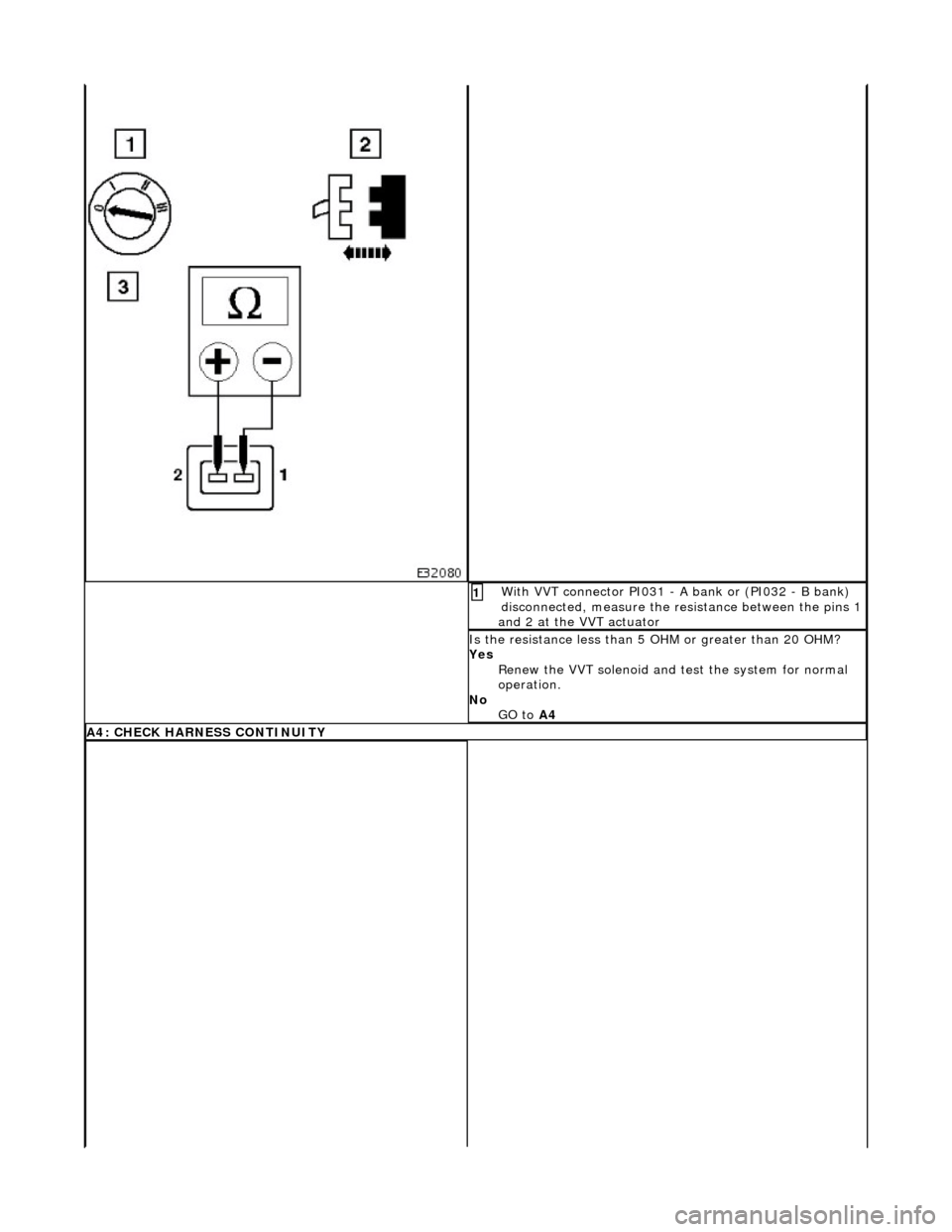
W
ith VVT connector PI031 - A bank or (PI032 - B bank)
disconnected, measure the resistance between the pins 1
and 2 at the VVT actuator
1
I
s the resistance less than 5
OHM or greater than 20 OHM?
Yes Renew the VVT solenoid and te st the system for normal
operation.
No GO to A4
A4: CHECK
HARNESS CONTINUITY