check oil JAGUAR X308 1998 2.G Manual Online
[x] Cancel search | Manufacturer: JAGUAR, Model Year: 1998, Model line: X308, Model: JAGUAR X308 1998 2.GPages: 2490, PDF Size: 69.81 MB
Page 1837 of 2490

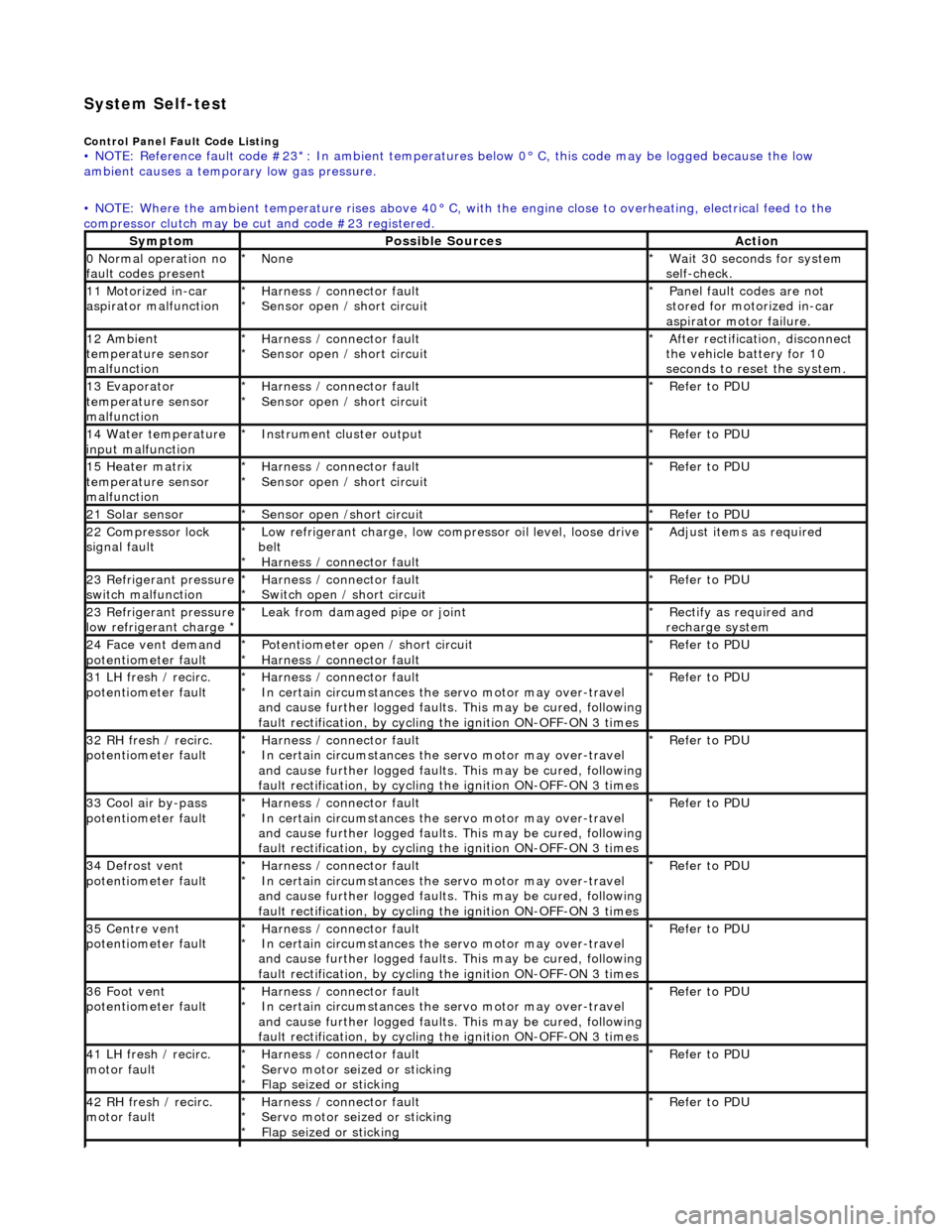
System Self-test
Control Panel Fault Code Listing • NOTE: Reference fault code #23*: In ambient temperatures below 0° C, this code may be logged because the low
ambient causes a tempor ary low gas pressure.
• NOTE: Where the ambient temperature rises above 40° C, with the engine close to overheating, electrical feed to the
compressor clutch may be cut and code #23 registered.
SymptomPossible SourcesAction
0 Normal operation no
fault codes presentNone
*Wait 30 seconds for system
self-check.
*
11 Motorized in-car
aspirator malfunctionHarness / connector fault
Sensor open / short circuit
*
*Panel fault codes are not
stored for motorized in-car
aspirator motor failure.
*
12 Ambient
temperature sensor
malfunctionHarness / connector fault
Sensor open / short circuit
*
*After rectification, disconnect
the vehicle battery for 10
seconds to reset the system.
*
13 Evaporator
temperature sensor
malfunctionHarness / connector fault
Sensor open / short circuit
*
*Refer to PDU
*
14 Water temperature
input malfunctionInstrument cl uster output
*Refer to PDU
*
15 Heater matrix
temperature sensor
malfunctionHarness / connector fault
Sensor open / short circuit
*
*Refer to PDU
*
21 Solar sensorSensor open /short circuit
*Refer to PDU
*
22 Compressor lock
signal faultLow refrigerant charge, low compressor oil level, loose drive
belt Harness / connector fault
*
*Adjust items as required
*
23 Refrigerant pressure
switch malfunctionHarness / connector fault
Switch open / short circuit
*
*Refer to PDU
*
23 Refrigerant pressure
low refrigerant charge * Leak from damaged pipe or joint
*Rectify as required and
recharge system
*
24 Face vent demand
potentiometer faultPotentiometer open / short circuit
Harness / connector fault
*
*Refer to PDU
*
31 LH fresh / recirc.
potentiometer faultHarness / connector fault
In certain circumstances the servo motor may over-travel
and cause further logged faults. This may be cured, following
fault rectification, by cycling the ignition ON-OFF-ON 3 times
*
*Refer to PDU
*
32 RH fresh / recirc.
potentiometer faultHarness / connector fault
In certain circumstances the servo motor may over-travel
and cause further logged faults. This may be cured, following
fault rectification, by cycling the ignition ON-OFF-ON 3 times
*
*Refer to PDU
*
33 Cool air by-pass
potentiometer faultHarness / connector fault
In certain circumstances the servo motor may over-travel
and cause further logged faults. This may be cured, following
fault rectification, by cycling the ignition ON-OFF-ON 3 times
*
*Refer to PDU
*
34 Defrost vent
potentiometer faultHarness / connector fault
In certain circumstances the servo motor may over-travel
and cause further logged faults. This may be cured, following
fault rectification, by cycling the ignition ON-OFF-ON 3 times
*
*Refer to PDU
*
35 Centre vent
potentiometer faultHarness / connector fault
In certain circumstances the servo motor may over-travel
and cause further logged faults. This may be cured, following
fault rectification, by cycling the ignition ON-OFF-ON 3 times
*
*Refer to PDU
*
36 Foot vent
potentiometer faultHarness / connector fault
In certain circumstances the servo motor may over-travel
and cause further logged faults. This may be cured, following
fault rectification, by cycling the ignition ON-OFF-ON 3 times
*
*Refer to PDU
*
41 LH fresh / recirc.
motor faultHarness / connector fault
Servo motor seized or sticking
Flap seized or sticking
*
*
*Refer to PDU
*
42 RH fresh / recirc.
motor faultHarness / connector fault
Servo motor seized or sticking
Flap seized or sticking
*
*
*Refer to PDU
*
Page 1883 of 2490

Belt tension is achieved by an automatic tensioner; neither the belt nor the tensioner require service apart from checking
the belt wear indicators at each normal service interval.
The minimum service life of the drive belt is 100,000 miles.
Never apply oil to the belt or to the belt tensioner.
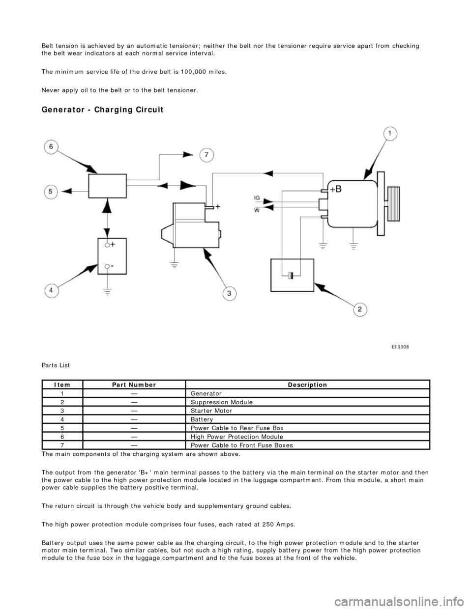
Generator - Charging Circuit
Parts List
The main components of the charging system are shown above.
The output from the generator 'B+' main te rminal passes to the battery via the main terminal on the starter motor and then
the power cable to the high power protection module located in the luggage compartment. From this module, a short main
power cable supplies the ba ttery positive terminal.
The return circuit is through the vehicle body and supplementary ground cables.
The high power protection mo dule comprises four fuses, each rated at 250 Amps.
Battery output uses the same power cable as the charging circ uit, to the high power protection module and to the starter
motor main terminal. Two similar cables, but not such a high rating, supply battery power from the high power protection
module to the fuse box in the luggage compartment an d to the fuse boxes at the front of the vehicle.
ItemPart NumberDescription
1—Generator
2—Suppression Module
3—Starter Motor
4—Battery
5—Power Cable to Rear Fuse Box
6—High Power Protection Module
7—Power Cable to Front Fuse Boxes
Page 1886 of 2490

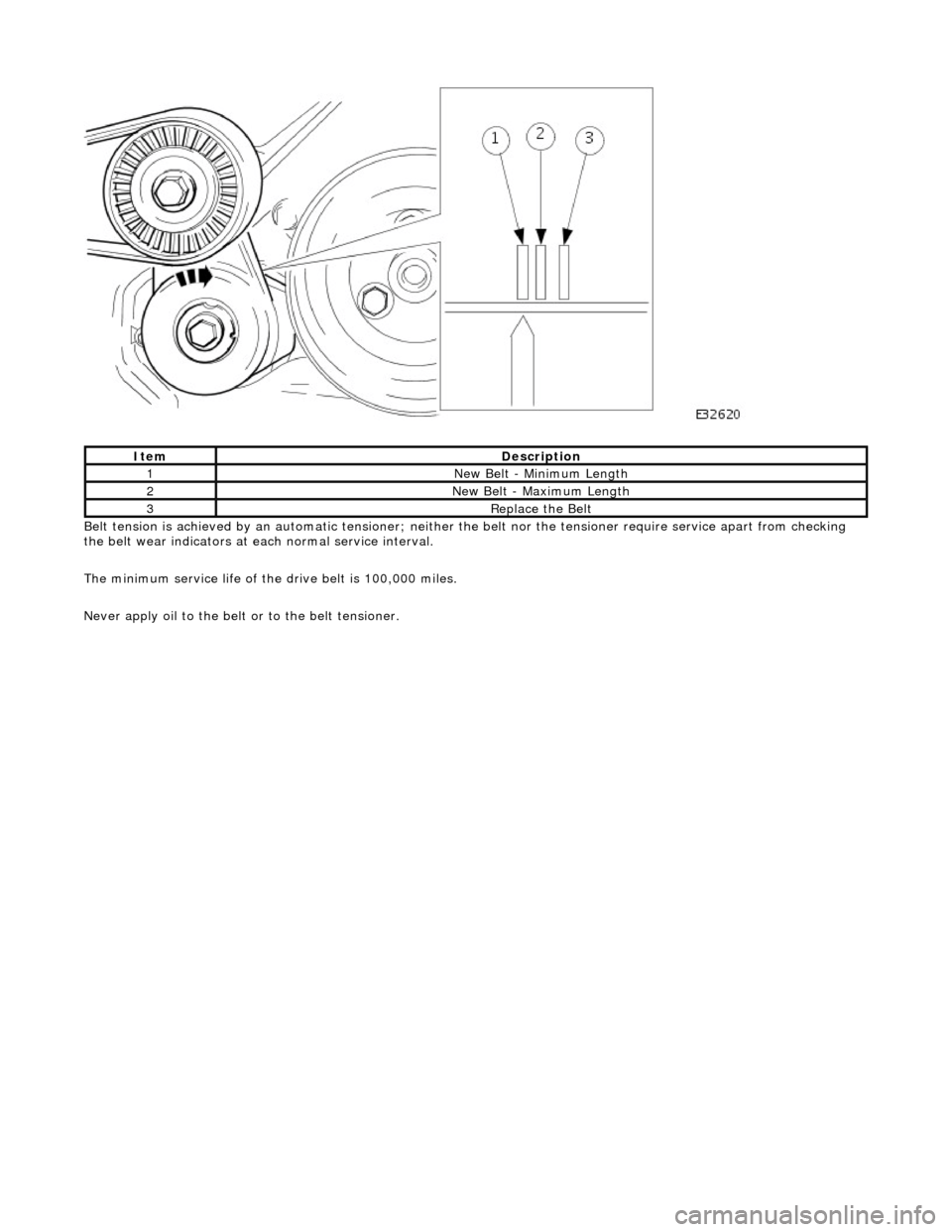
Belt tension is achieved by an automatic tensioner; neither the belt nor the tensioner require service apart from checking
the belt wear indicators at each normal service interval.
The minimum service life of the drive belt is 100,000 miles.
Never apply oil to the belt or to the belt tensioner.
ItemDescription
1New Belt - Minimum Length
2New Belt - Maximum Length
3Replace the Belt
Page 2381 of 2490

The body is pre-treated to ensure high resistance to corrosion and stone chip dama ge. Prior to the first major pre-treatment process, the body shell is high-pressure washed to remove any metal dust and residual oil.
The first major pre-treatment process consists of phosphate and electro-paint deposition, which together with zinc coating,
forms the basis of the corrosion protection. This process includes high pressure knock-off, alkali de-greasing, zinc phosphate
conversion of body steel (dissolving iron and coating with zinc phosphate crystals), trivalent chrome rinsing and
demineralized water rinsing, seal ing all chemicals and impurities.
Both dip and spray techniques are employed and the bodies are submerged to the waistline during the first and third rinses
of the main phosphate clean. Chemical strengths and soluti on temperatures are continuously monitored and accurately
controlled throughout the process.
An 80% water primer is then cathodic elec tro-deposition applied to the thoroughly cleansed bodies in a uniform 'sag-free'
film 18 to 32 micron thick. Optimum durabi lity of the electroprimer is achieved by finally curing in a stoving oven at 165 В°C
for a period of 20 minutes.
All underbody seams of the fully primed bo dies are then manually sealed, to prevent water and dust ingress into the vehicle
and to enhance corrosion protection.
An 800 to 1000 g/m2 PVC coating is semi-automatic airless sp ray applied to the underside of the main floor panels, trunk
floor and rear wheel arches (ref. illustration above).
The upper panels of primed and external ly sealed bodyshells are next lightly scuffed to remove imperfections and a PVC
coating is applied to all internal seams by an airless spray technique. A PVC bead seal is also applied to the doors, hood and
trunk clinch joints.
Following anti-corrosion, sealing and primin g treatment, the bodies enter the first stage of 'cosmetic' painting. This consists
of the application of two coats of a highly chip resistant po lyester surfacer, employing high voltage electrostatic 'spinning
bells', to achieve a final film thickness of 35 to 50 micron. Between surfacer coats, a polyurethane coat is automatically
applied to the sills to impart even greater resistance to stone chipping.
All interior panels are then painted us ing a color keyed sealer, wet-on-wet wi th a surfacer material, after which the
bodyshells are stoved at 160 В°C for a period of 20 minutes. Further protection agai nst corrosion is provided by a medium
solids black pigmented wax which is airless spray applied to vehicle undersides.
Wax Injected Box Sections
Critical body box-sections are si milarly protected by spray injecting a high solids wax. This is then re-flowed at 70 to 90 В°C
to achieve optimum seam/joint penetratio n and form a resilient and durable internal coating (ref. illustration above).
After full wet sanding, rinsing and drying to provide a good su bstrate, a color-keyed semi-matt sealer co at is applied using
electrostatic bells to achieve a film build of 25 to 35 micron . The bodies are then stoved for a further 20 minutes at a
temperature of 145 В°C and subjected to a local 'seek-and-find' de -nib operation prior to the final two coat process. The final
top coat finish is achieved by using poly ester base coat colors and an acrylic sag resistant clear coat. This clear over base
(COB) process produces a high gloss, durabl e paint finish with a film thickness of 50 to 65 micron, which is finally cured at a
temperature of 135В°C for 20 minutes.
The Munsell three dimensional system of color management is em ployed to achieve highly accurate control of vehicle colors.
This system ensures that paint pigmentations are accurately maintained and facilitates vigorous final checking of finished
vehicles for color match. The hu e of individual panels such as trunk lids, doors and hoods is in some instances adjusted to
offset the effects of differing light angles. Where applicable, coachlines are manually applied and radiant heat cured on the
completed and valeted vehicle prior to hand spray applic ation of a protective wax coat.
Introduction
All repairs, whether structural or cosmetic must return the vehicle to the original manufactured condition with regard to
occupant safety, dimensional accuracy, fi nish and corrosion protection, and ensure continuation of the Paint Surface and
Corrosion warranty where applicable.
Similarly, repaired vehicles must be fu lly checked, and where appropriate reset, with regard to steering, suspension,
braking, and occupant restraint systems.