JAGUAR X308 1998 2.G Repair Manual
X308 1998 2.G
JAGUAR
JAGUAR
https://www.carmanualsonline.info/img/21/7640/w960_7640-0.png
JAGUAR X308 1998 2.G Repair Manual
Page 1279 of 2490
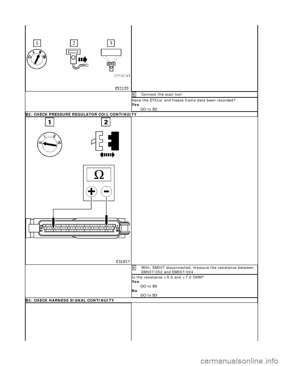
Connect the scan tool 1
Have the DTC(s) and freeze frame data been recorded?
Yes GO to B2
B2: CHECK PRESSURE REGULATOR COIL CONTINUITY
With, EM007 disconnected, measure the resistance between
EM007/052 and EM007/004 1
Is the resistance >5.0 and <7.0 OHM?
Yes
GO to B6
No GO to B3
B3: CHECK HARNESS SIGNAL CONTINUITY
Page 1308 of 2490
With EM007 and EM046 disconnected, measure the
resistance between EM046/010 and EM007/044 1
Is the resistance < 0.5 OHM?
Yes GO to E4
No Inspect harness / connectors EM007 and EM046 for damage,
corrosion, bent / pushed back pins. Repair as necessary and
test the system for normal operation.
E4: CHECK OUTPUT SPEED SENSOR COIL CONTINUITY
Page 1313 of 2490
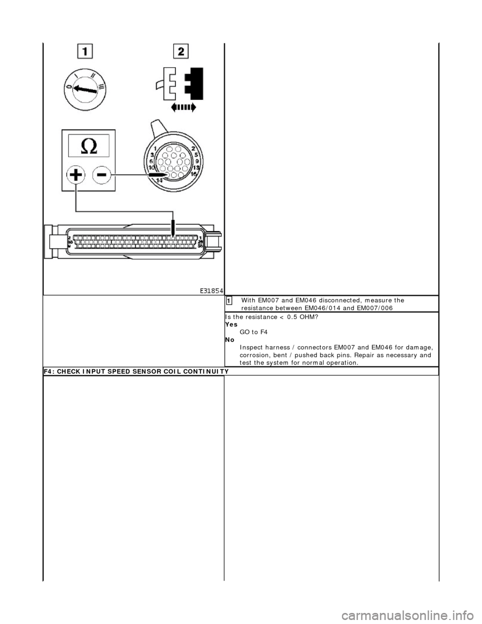
With EM007 and EM046 disconnected, measure the
resistance between EM046/014 and EM007/006 1
Is the resistance < 0.5 OHM?
Yes GO to F4
No Inspect harness / connectors EM007 and EM046 for damage,
corrosion, bent / pushed back pins. Repair as necessary and
test the system for normal operation.
F4: CHECK INPUT SPEED SENSOR COIL CONTINUITY
Page 1318 of 2490
With EM007 and EM046 disconnected, measure the
resistance between EM046/010 and EM007/044 1
Is the resistance < 0.5 OHM?
Yes GO to G4
No Inspect harness / connectors EM007 and EM046 for damage,
corrosion, bent / pushed back pins. Repair as necessary and
test the system for normal operation.
G4: CHECK OUTPUT SPEED SENSOR COIL CONTINUITY
Page 1323 of 2490
With EM007 and EM046 disconnected, measure the resistance between EM046/014 and EM007/006 1
Is the resistance < 0.5 OHM?
Yes GO to I4
No Inspect harness / connectors EM007 and EM046 for damage,
corrosion, bent / pushed back pins. Repair as necessary and
test the system for normal operation.
I4: CHECK INPUT SPEED SENSOR COIL CONTINUITY
Page 1326 of 2490
With EM007 and EM046 disconnected, measure the resistance between EM046/010 and EM007/044 1
Is the resistance < 0.5 OHM?
Yes GO to I7
No Inspect EM007 and EM046 for corrosion, bent / pushed back
pins or locate and repair th e harness Test the system for
normal operation
I7: CHECK OUTPUT SPEED SENSOR COIL CONTINUITY
Page 1336 of 2490
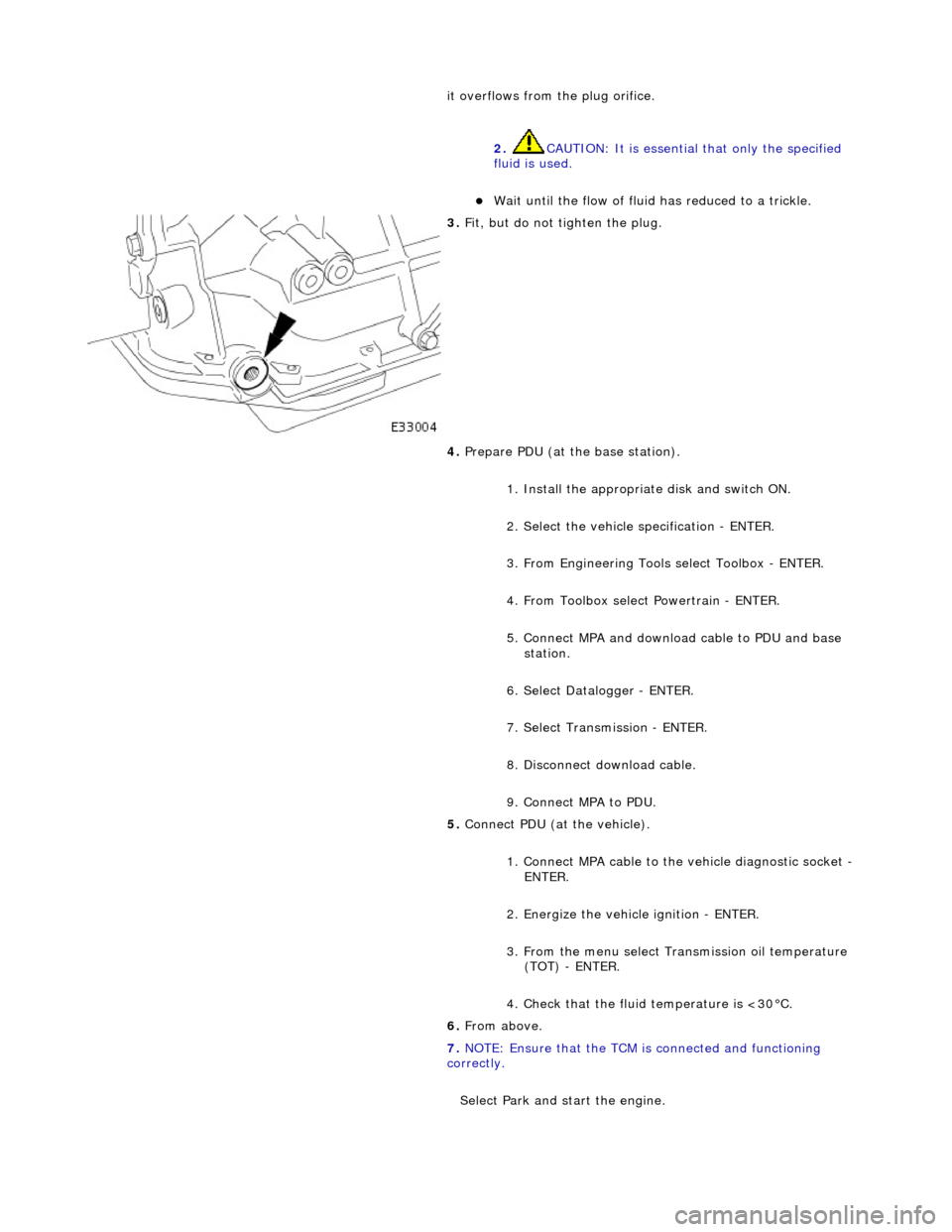
it overflows from the plug orifice. 2. CAUTION: It is essential that only the specified
fluid is used.
пЃ¬Wait until the flow of fluid has reduced to a trickle.
3. Fit, but do not tighten the plug.
4. Prepare PDU (at the base station).
1. Install the appropriat e disk and switch ON.
2. Select the vehicle specification - ENTER.
3. From Engineering Tools select Toolbox - ENTER.
4. From Toolbox select Powertrain - ENTER.
5. Connect MPA and download cable to PDU and base station.
6. Select Datalogger - ENTER.
7. Select Transmission - ENTER.
8. Disconnect download cable.
9. Connect MPA to PDU.
5. Connect PDU (at the vehicle).
1. Connect MPA cable to the vehicle diagnostic socket -
ENTER.
2. Energize the vehicle ignition - ENTER.
3. From the menu select Transmission oil temperature (TOT) - ENTER.
4. Check that the fluid temperature is <30В°C.
6. From above.
7. NOTE: Ensure that the TCM is connected and functioning
correctly.
Select Park and start the engine.
Page 1382 of 2490

Automatic Transmission/Transaxle - 4.0L NA V8 - AJ27/3.2L NA V8 - AJ26
- Torque Converter
Disassembly and Assembly of Subassemblies
Special Tool(s)
Lifting handle
307-139
1. Remove the transmission unit from the vehicle; 44.20.01.
2. Remove the torque converter from the transmission unit.
пЃ¬Install lifting handles 307 - 139.
3. Remove lifting handles 307 - 139 from the torque converter.
4. Clean the torque conver ter and mating faces.
5. CAUTIONS:
Use extreme care NOT to damage the oil seal with the
converter spigot.
Ensure that the conver ter is fully located.
Install the torque converter.
1. Install lifting handles 307 - 139.
2. Lubricate the front pump seal.
пЃ¬To facilitate location, rotate the converter as it is being
fitted and note the engagement of splines and oil pump
drive.
6. Check that the three conver ter fixing boss faces are
approximately 8,0 mm proud of the transmission mounting
face.
7. Remove lifting handles 307 - 139 from the torque converter.
8. Install the transmission unit; refer to Operation 44.20.01,
noting especially the alignment instructions.
Page 1401 of 2490
Pinpoint test A: P0740
DTC P0730 Incorrect gear ratioEngaged gear implausible / transmission
slipping Oil level low
Valve body assembly faulty
Transmission faulty
*
*
*
*GO to Pinpoint Test H *
DTC P0780 Shift malfunctionValve body assembly faulty
Transmission faulty
*
*GO to Pinpoint Test H *
PINPOINT TEST A : P0740
TEST CONDITIONSDETAILS/RESULTS/ACTIONS
A1: RETRIEVE DTCS
• NOTE: Battery and or ECM disconnection prior to scanning wi
ll erase all data, ensure that the correct DTC is present.
Connect the scan tool 1
Have the DTC(s) and freeze frame data been recorded?
Yes GO to A2
A2: CHECK TORQUE CONVERTER CLUTCH SOLENOID RESISTANCE
With, EM062 disconnected, measure the resistance between 1
Page 1434 of 2490
Installation
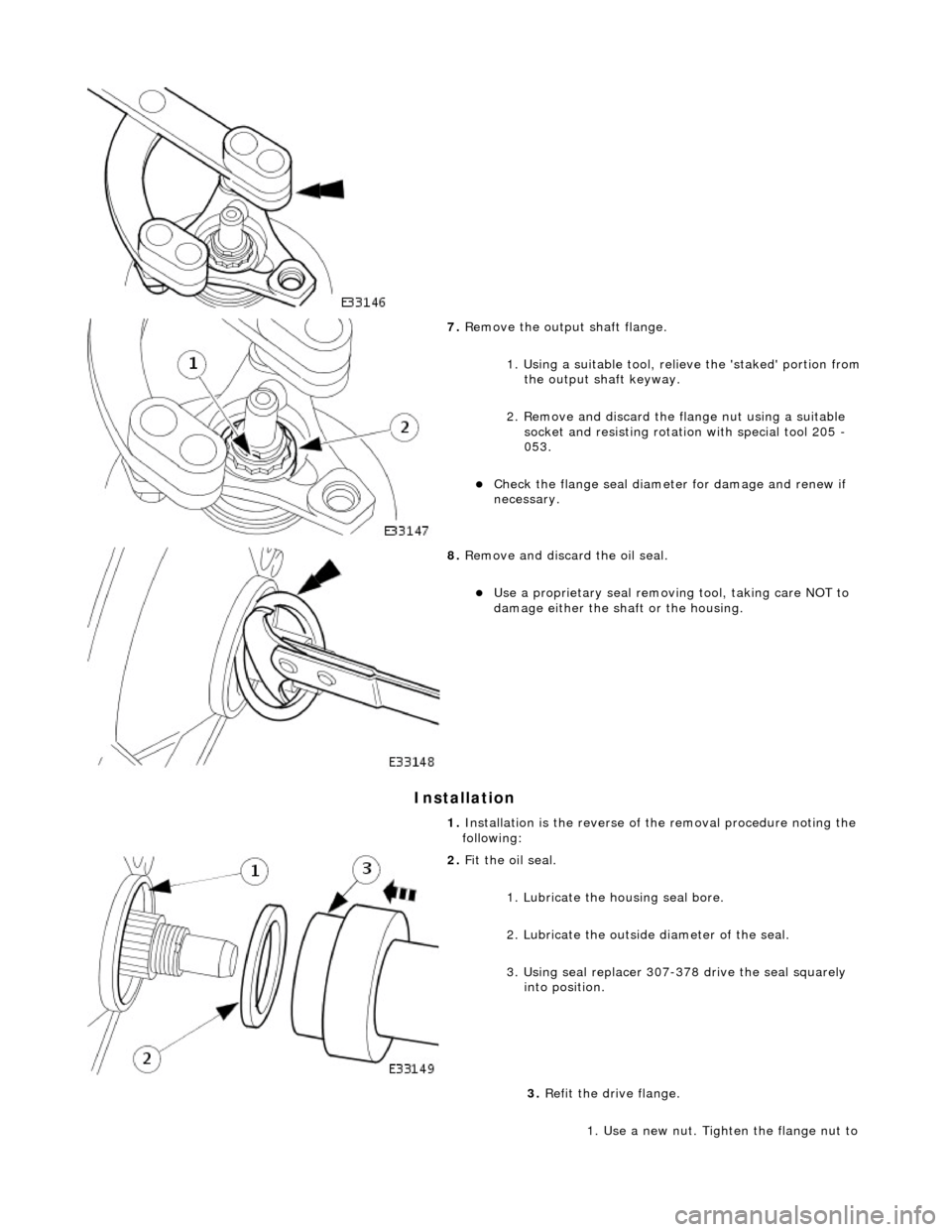
7. Remove the output shaft flange.
1. Using a suitable tool, reli eve the 'staked' portion from
the output shaft keyway.
2. Remove and discard the fl ange nut using a suitable
socket and resisting rotation with special tool 205 -
053.
пЃ¬Check the flange se al diameter for damage and renew if
necessary.
8. Remove and discard the oil seal.
пЃ¬Use a proprietary seal removing tool, taking care NOT to
damage either the shaft or the housing.
1. Installation is the re verse of the removal procedure noting the
following:
2. Fit the oil seal.
1. Lubricate the housing seal bore.
2. Lubricate the outside diameter of the seal.
3. Using seal replacer 307-378 drive the seal squarely into position.
3. Refit the drive flange.
1. Use a new nut. Tighten the flange nut to


