205-2 JAGUAR X308 1998 2.G Workshop Manual
[x] Cancel search | Manufacturer: JAGUAR, Model Year: 1998, Model line: X308, Model: JAGUAR X308 1998 2.GPages: 2490, PDF Size: 69.81 MB
Page 231 of 2490

Re
move bearin
g spacer.
Remove ou
ter bearing.
14. Pack new inner and outer bear ings with Shell Retinax 'A'
grease.
15
.
Install outer bearing and usin g special tool 205-234, fully
seat seal in hub carrier.
16
.
Using a press, install hub in carrier/bearing assembly.
17
.
Install inner bearing assembly.
1. Install bearing spacer.
2. Install bearing shim.
3. Install inner bearing.
18. Determine hub end float.
Measure an
d record end-float as a datum.
Calculating from datum, select
a sh
im that will achieve a
0.076 mm end-float.
19. Install new bearing shim.
Page 232 of 2490

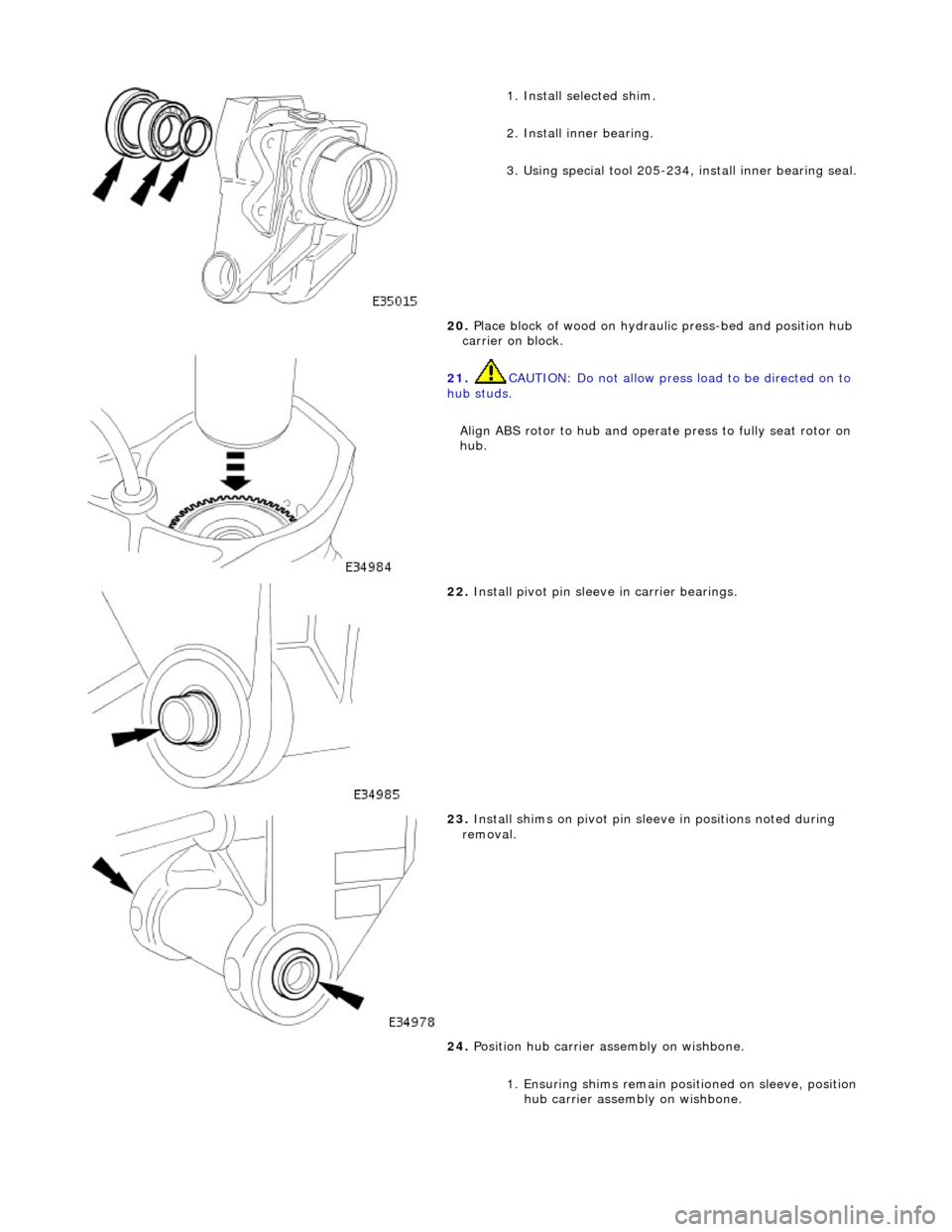
1. Ins
tall selected shim.
2. Install inner bearing.
3. Using special tool 205-234, install inner bearing seal.
20. Place block of wood on hydrau lic press-bed and position hub
carrier on block.
21 . CAUTI
ON: Do not allow press load to be directed on to
hub studs.
Align ABS rotor to hub and operat e press to fully seat rotor on
hub.
22 . Install piv
ot pin sleeve in carrier bearings.
23 . Inst
all shims on pivot pin slee
ve in positions noted during
removal.
24. Position hub carrier as sembly on wishbone.
1. Ensuring shims remain posi tioned on sleeve, position
hub carrier assembly on wishbone.
Page 237 of 2490

Rear Suspension - Wheel Hub
Seal
Re
moval and Installation
Remov
al
S
pecial Tool(s)
Hub Holdin
g Tool
204-195 (JD227)
Hub Pu
ller
204-011 (JD 1D)
R
ear-Hub Remover
204-113 (JD 132)
O
il Seal Remover/Replacer
205-234 (JD 550-1)
1. CAUTION: Replacement of nuts and bolts: Various
thread-locking devices are used on nuts and bolts throughout the
vehicle. These devices restrict the number of times a nut or bolt
can be used. See section 100-00 for information.
Release parking brake.
2. R
aise the vehicle on a four-post lift.
3. Fully
slacken but do not remove parking brake cable adjuster
nut.
4. Release appropriate side parkin g brake cable from connecting
Page 243 of 2490

I
nstallation
33
.
Using approved cleaning agents:
Wash an
d thoroughly dry inner and outer bearings.
Thorough
ly clean hub carrier payi
ng particular attention to
bearing cups.
Thoroughl
y clean hub.
1. Grease bearings.
Pack inner and outer bea
ring races with Shell Retinax 'A'
grease:
Appl
y a film of shell Retinax
'A' grease to bearing cups
2. Install outer bearing in hu
b carrier and fully seat new seal
using special tool 205-234.
3. Apply a th
in film of Shell Retinax 'A' grease to hub shaft and
install hub in carrier /bearing assembly.
4. Install inner bearing assembly and seal.
1. Install bearing spacer.
Page 244 of 2490

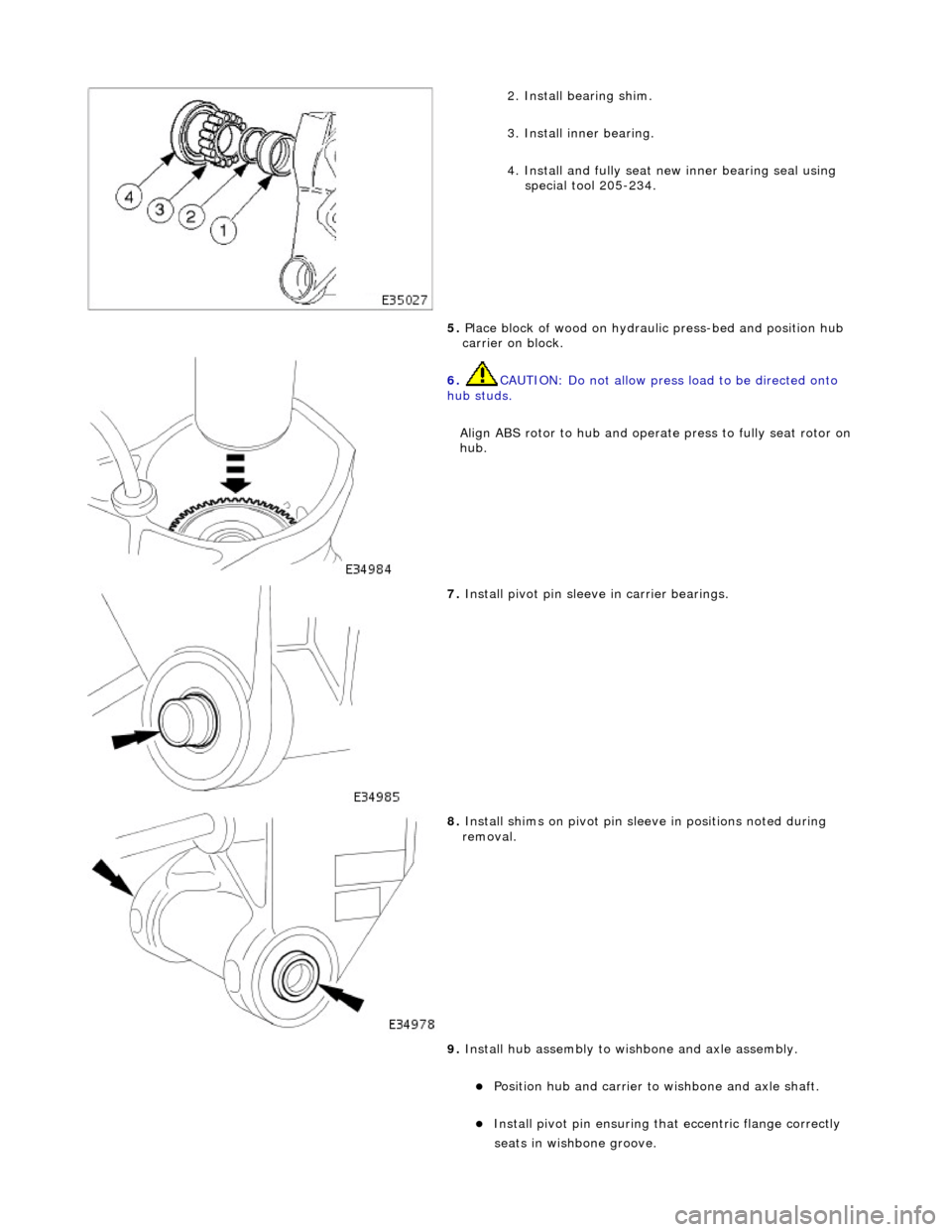
2.
Install bearing shim.
3. Install inner bearing.
4. Install and fully seat new inner bearing seal using special tool 205-234.
5. Place block of wood on hydrau lic press-bed and position hub
carrier on block.
6. CAUTIO
N: Do not allow press
load to be directed onto
hub studs.
Align ABS rotor to hub and operat e press to fully seat rotor on
hub.
7. Install piv o
t pin sleeve in carrier bearings.
8. Inst al
l shims on pivot pin slee
ve in positions noted during
removal.
9. Install hub assembly to wi shbone and axle assembly.
Position hub and carr
ier to wishbone and axle shaft.
Install pivo
t pin ensuring that
eccentric flange correctly
seats i
n wishbone groove.
Page 295 of 2490

R
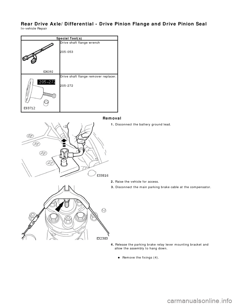
ear Drive Axle/Differential - Drive Pinion Flange and Drive Pinion Seal
In-v
ehicle Repair
Remov
al
S
pecial Tool(s)
Drive sh
aft flange wrench
205-053
D
rive shaft flange remover replacer.
205-272
1. Di
sconnect the battery ground lead.
2. Raise the vehicle for access.
3. Disconnect the main parking br ake c
able at the compensator.
4. Release the parking brake relay lever mounting bracket and
allow the assembly to hang down.
R
emove the fixings (4).
Page 296 of 2490

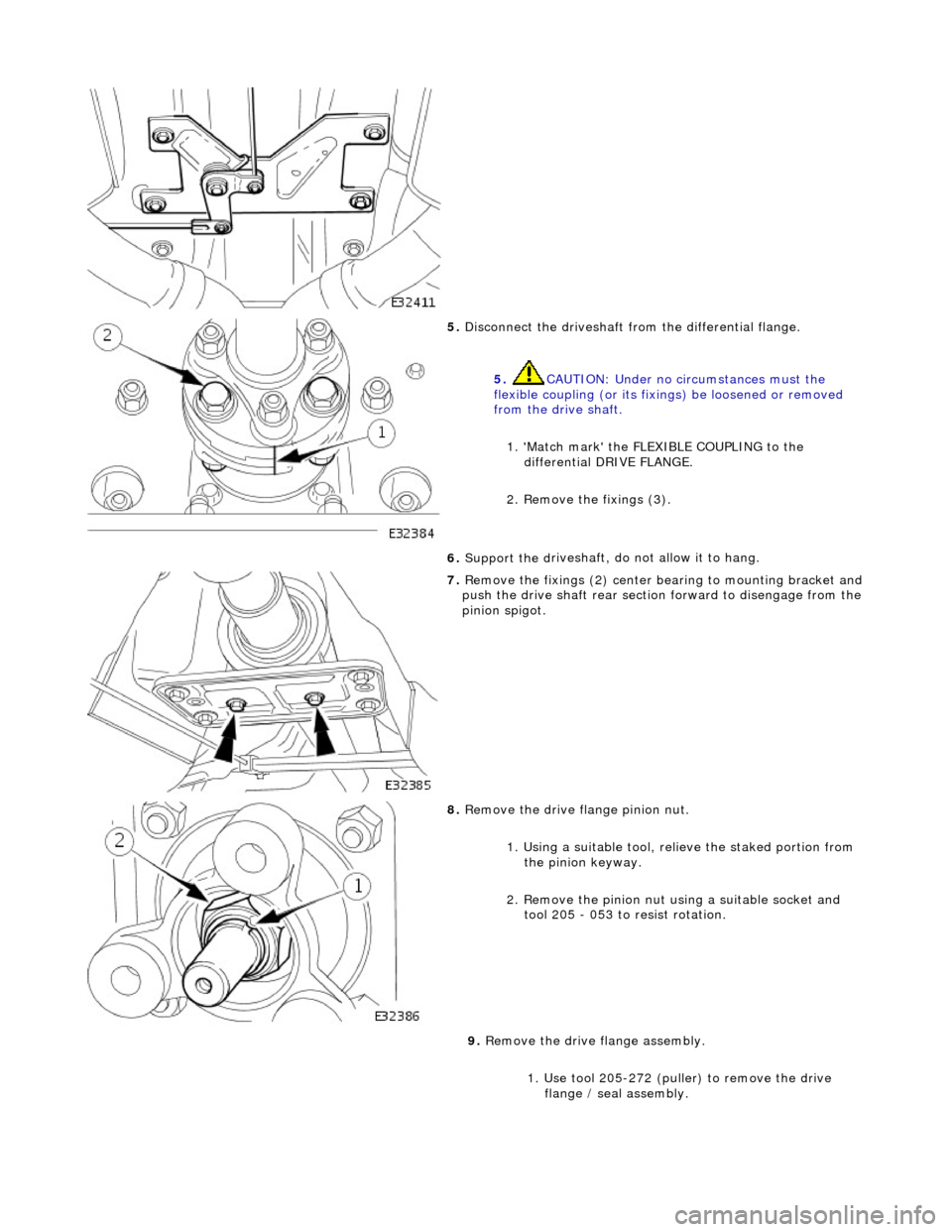
5. Disconne
ct the driveshaft fr
om the differential flange.
5. CAUTION: Under no circumstances must the
flexible coupling (or its fixings) be loosened or removed
from the drive shaft.
1. 'Match mark' the FLEX IBLE COUPLING to the
differential DRIVE FLANGE.
2. Remove the fixings (3).
6. Support the d
riveshaft, do not allow it to hang.
7. Re
move the fixings (2) center
bearing to mounting bracket and
push the drive shaft rear sectio n forward to disengage from the
pinion spigot.
8. Remove the drive flange pinion nu
t.
1. Using a suitable tool, re lieve the staked portion from
the pinion keyway.
2. Remove the pinion nut using a suitable socket and tool 205 - 053 to resist rotation.
9. Remove the drive flange assembly.
1. Use tool 205-272 (puller) to remove the drive flange / seal assembly.