Suspension fault JAGUAR X308 1998 2.G Workshop Manual
[x] Cancel search | Manufacturer: JAGUAR, Model Year: 1998, Model line: X308, Model: JAGUAR X308 1998 2.GPages: 2490, PDF Size: 69.81 MB
Page 36 of 2490
Gener
al specifications (including setting-up information, capacities, lubricants, fluids, sealants and adhesives).
To
r
que specifications.
Description and Operation
A g
eneral illustration and part
s list to identify the components which comp rise a particular system or assembly.
A b
rief description of the system operating characteristics or description of the assembly.
A d
escription of each component and its function.
Diagnosis and Testing
D e
scriptions of how to iden
tify system problems.
Inspection and verifi
cation information.
S
y
mptom charts comprising fault conditions, possible sources and actions.
General Procedures
G e
neral maintenance procedures, including adjustment, alig
nment, bleeding and filling, with illustrated steps and
supporting text.
Tigh te
ning torque specifications, shown in the illustrations.
Removal and Installation
Com p
onent removal and installation maintenance proced
ures, with illustrated steps and supporting text.
Tighte
ning torque specifications, shown in the illustrations.
An i
llustrated tool
chart for each proced
ure requiring the use of special tools.
Disassembly and Assembly
Compon ent disassembly and
assembly
maintenance procedures, with illust rated steps and supporting text.
Tighte
ning torque specifications, shown in the illustrations.
An i
llustrated tool
chart for each proced
ure requiring the use of special tools.
Repairs and Replacem
ents
Wh
en s
ervice parts are required, it is essential that only genuine Jaguar/Daimler replacements are used.
Attention is drawn to the following points concerning repa irs and the fitting of replacement parts and accessories:
Safety feat
ures embodied in the vehicle
may be impaired if other than genuine parts are fitted. In certain territories,
legislation prohibits the fitting of pa rts which are not produced to the vehi cle manufacturer's specification.
Torque wrench setting figures given i
n this manual must be strictly adhered to. Locking devices, where specified,
must be fitted. If the efficiency of a locking device is impaired during removal it must be renewed.
O w
ners purchasing accessories
while travelling abroad should ensure that the accessory and its fitted location on the
vehicle conform to mandatory requirements existing in their country of origin.
The vehicle warranty may be invali
dated by the fitting
of other than genuine Ja guar/Daimler parts. All
Jaguar/Daimler replacements have the fu ll backing of the factory warranty.
Jaguar/Daimler dealers are obliged to
supply only genuine service parts.
Thread Locking Devices
P a
tched Fasteners
Two types
of
patched fastener are essentially used on certai
n suspension, steering and other critical components, where
operational movement of the component necessitates positive thread locking. Standard patched fasteners have part
numbers bearing the suffix le tter M. For identification of special patched fa steners, refer to the list of patched fasteners
below, or the relevant component drawings.
Jaguar Specification JFS 02.01.02 patched fasteners incorporate a micro-encapsulated adhesive which is released into the
mating threads during tightening. Following final tightening, the adhesive in this type of patched fastener must be allowed a
period to cure before the component/vehicle is used. On removal, this type of fastener must be discarded and a new
Page 276 of 2490
Is hard-wi
red to the instrume
nt cluster message center.
Is hard
-wired to the J1962 diagnostic connector.
Op
era
tion
Th
e
system selects the soft or
firm damper setting according to the current ro ad and driving conditions, to optimise vehicle
ride and handling.
With the vehicle stationary, the dampers are in the firm setting, but will normally switch to the soft setting when the vehicle
exceeds 8 km/h (5 mile/h); all dampers are switched simultaneously.
Sudden movement of the vehicle body, in response to road inputs, is detected by the vertical accelerometers, and the ADCM
switches the dampers to the firm setting to give improved damping of the resultant oscillations.
When cornering forces are detected by th e lateral accelerometer, the ADCM switches the dampers to the firm setting to
reduce the roll rate an d improve wheel control.
After the event has passed, the dampers revert to the soft setting.
When the footbrake is applied, the ADCM re ceives a signal and calculates the rate of vehicle deceleration. If the deceleration
rate is greater than a certain threshold, the dampers are switched to the firm setting to reduce the pitch rate and improve
wheel control.
If a system failure occurs, the ADCM grounds the output line to the instrument cluster message center, which displays a
text warning SUSPENSION FAULT and illuminates the amber warning lamp. Under fault conditions the system always fails to
the firm setting, so that the vehicle will be safe to drive un der all road and driving conditions.
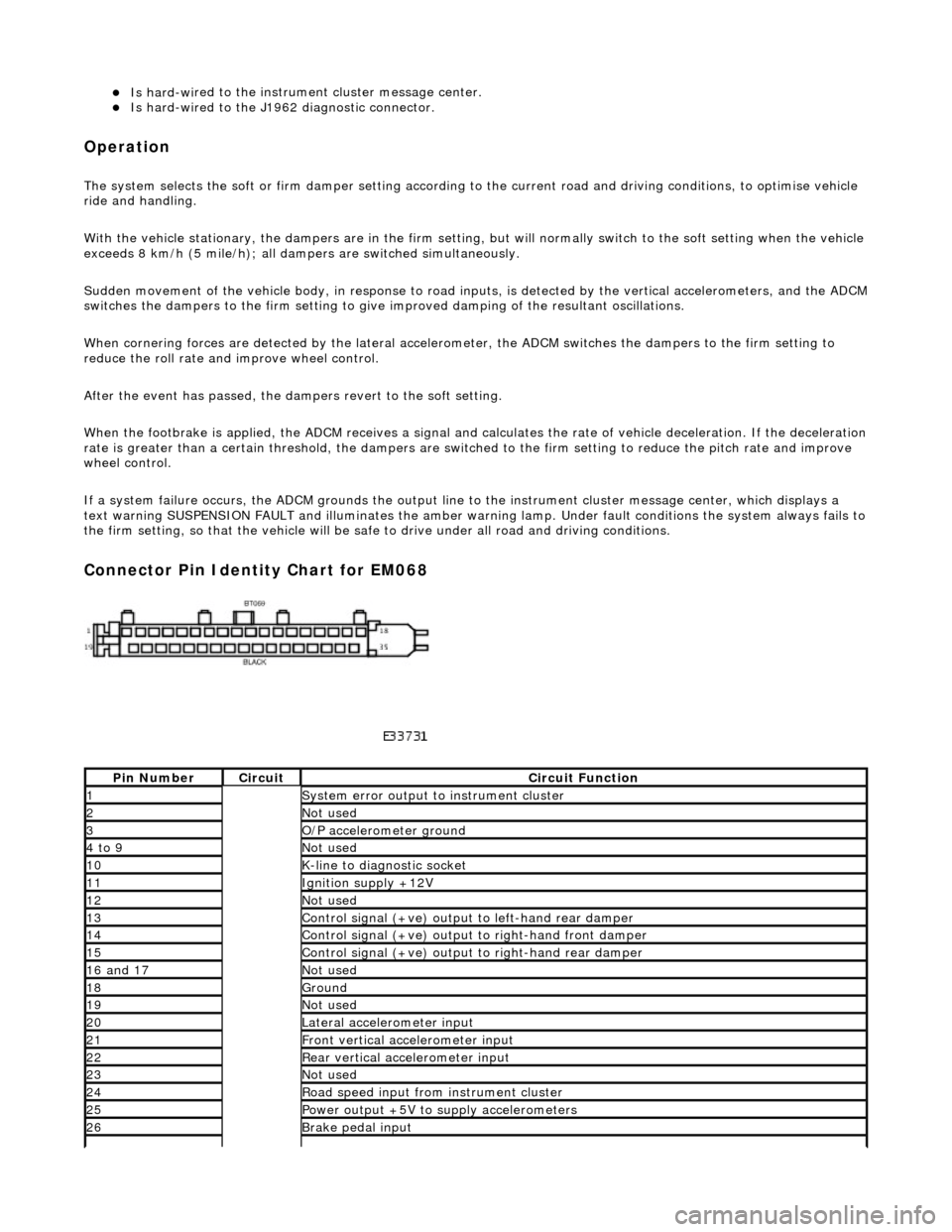
Connector Pin Identity Chart for EM068
Pin
Number
Ci
rcui
t
Circuit Functi
on
1System erro
r output to instrument
cluster
2Not
used
3O/
P a
ccelerometer ground
4 to
9
Not
used
10K-
li
ne to diagnostic socket
11Ignition su
pply +12V
12Not
used
13Control signal (+ve) output
to l
eft-hand rear damper
14Control signal (+ve) output
to right-hand front damp
er
15Control signal (+ve) output
to right-hand rear
damper
16
a
nd 17
No
t
used
18Ground
19No
t
used
20Lateral
accelerometer i
nput
21Front vertical ac
celerometer in
put
22Rear vertical
acce
lerometer input
23No
t
used
24R
o
ad speed input from
instrument cluster
25Power output +5V to suppl y accelerometers
26Brake peda
l input
Page 278 of 2490
Vehicle Dynamic Suspension - Vehicle Dynamic Suspension
Diagn
osis and Testing
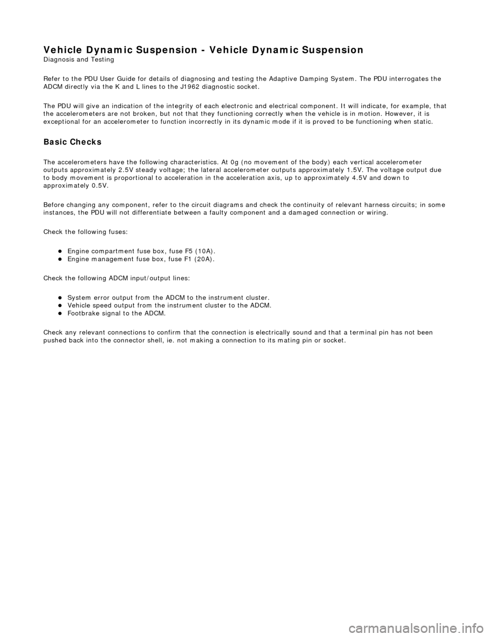
Refer to the PDU User Guide for details of diagnosing and testing the Adaptive Damping System. The PDU interrogates the
ADCM directly via the K and L lines to the J1962 diagnostic socket.
The PDU will give an indication of the integrity of each electron ic and electrical component. It will indicate, for example, that
the accelerometers are not broken, but not that they functionin g correctly when the vehicle is in motion. However, it is
exceptional for an accelero meter to function incorrectly in its dynamic mode if it is proved to be functioning when static.
Basic Checks
The accele
rometers have the following ch
aracteristics. At 0g (no movement of the body) each vertical accelerometer
outputs approximately 2.5V steady voltage; the lateral acce lerometer outputs approximately 1.5V. The voltage output due
to body movement is proportional to acceleration in the acceleration axis, up to approximately 4.5V and down to
approximately 0.5V.
Before changing any component, refer to the circuit diagrams and check the cont inuity of relevant harness circuits; in some
instances, the PDU will not different iate between a faulty component an d a damaged connection or wiring.
Check the following fuses:
En
gine compartment fuse
box, fuse F5 (10A).
Engine m
anagement fuse
box, fuse F1 (20A).
Check the following ADCM input/output lines:
Sy stem erro
r output from the ADCM
to the instrument cluster.
Vehicl
e speed output from the inst
rument cluster to the ADCM.
Foo
tbrake signal to the ADCM.
Check any relevant connections to confirm that the connection is electrically sound and that a terminal pin has not been
pushed back into the connector shell, ie. not ma king a connection to its mating pin or socket.
Page 461 of 2490
sus
pension components
and for damaged coil springs in the front suspension.
as necessary. For addi tional information,
REF
ER to Section 204
-0
2 Rear Suspension
. I
NSTALL new front suspension components
as necessary. For addi tional information,
REFER to Section 204
-01
Front Suspension
.
Chec
k the rear suspension
for loose or worn
suspension components.
TIGHTE
N or INSTALL new components as
necessary. For additi onal information,
REFER to Section 204
-0
2 Rear Suspension
.
Incorre
ct underbody
alignment.
CHECK
underbody alignment. For additional
information,
REFER to Section 502
-00
Uni
-Body, Subframe and M
ounting System
.
Poor r
eturnability of the
steering
Lower steeri
ng column
interference.
CHECK
the steering co
lumn is free from
interference from the en gine harness, sound
proofing or the floor covering.
Incorrect
tire pressure.
CHECK
and ADJUST the tire pressure. For
additional information,
REFER to Section 204
-0
4 Wheels and Tires
.
Incorrect
tire size or type.
IN
STALL a new tire as necessary. For
additional information,
REFER to Section 204
-0
4 Wheels and Tires
.
Steeri
ng column upper
shroud fouling on the steering wheel.
CHECK
steering column upper shroud for
fouling. ADJUST as necessary.
Steeri
ng column universal
joints binding.
IN
STALL a new steering column. For
additional information,
REFER to Section 211
-0
4 Steering Column
.
Steeri
ng column shaft floor
seal binding.
CHE
CK the steering column shaft floor seal
for correct fitm ent and REFIT as necessary.
Steeri
ng column shaft floor
seal may be torn.
IN
STALL a new steering column shaft floor
seal as necessary.
Bin
ding or damaged tie-
rods.
CHECK
tie-rod end for excessive wear or
tightness in ball joint. INSTALL a new tie- rod end. For additional information,
REFER to Section 211
-0
3 Steering Linkage
.
D
amaged or worn front
suspension components.
I
NSTALL new front suspension components
as necessary. For addi tional information,
REFER to Section 204
-01
Front Suspension
.
Incorre
ct toe adjustment.
AD
JUST as necessary. For additional
information,
REFER to Section 204
-00
Suspension
Sy
stem
- General
Information
.
Excessive steeri
ng efforts
required during low speed
manoeuvring and/or during parking manoeuvres
Low power steer
ing fluid.
CHE
CK steering system
for signs of steering
fluid loss.
BLEE
D the power steering system. For
additional information,
REFER to Section 211
-0
0 Steering System
- General Informati
on
.
Damaged accessory driv
e
belt tensioner.
INST
ALL a new accessory drive belt
tensioner.
Hose or cooler li
ne
restriction.
CHECK
hose or cooler lines for correct
routing.
INST
ALL a new hose as necessary.
Fl
uid aeration.
BLEE
D the system. For additional
information,
REFER to Power Steering System Bleeding
in t
his section.
Steeri
ng transducer not
closed - no feed voltage.
CHECK
the steering transducer circuit. For
additional information, REFER to the wiring diagrams.
Carry ou
t the electrical checks and tests.
For additional information, REFER to the
Electrical Checks and Tests in this section.
Steeri
ng transducer not
closed - cable fault.
CHECK
the steering transducer circuit. For
additional information, REFER to the wiring diagrams.
Carry ou
t the electrical checks and tests.
Page 463 of 2490
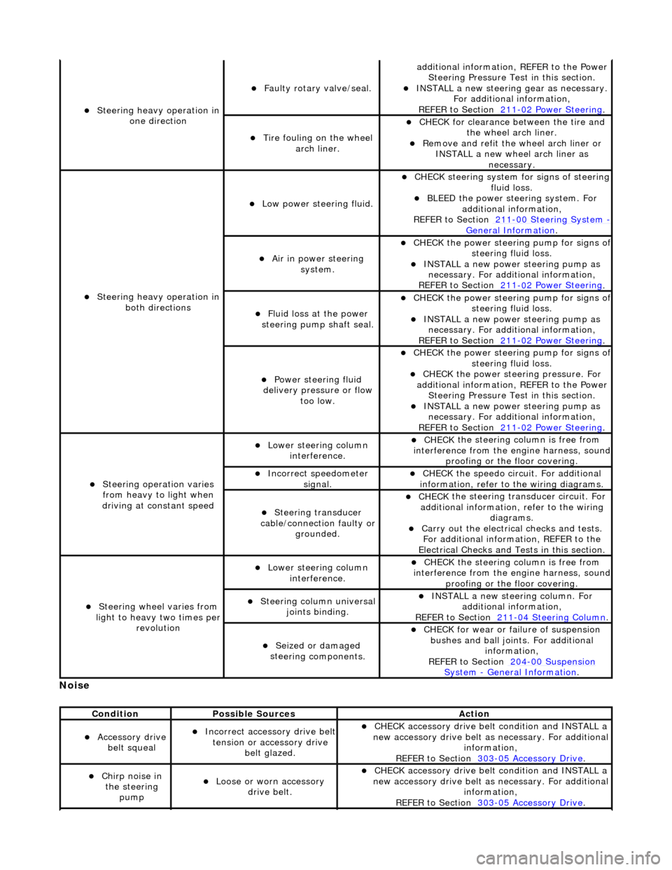
No
ise
S
teering heavy operation in
one direction
F
aulty rotary valve/seal.
addi
tional information, REFER to the Power
Steering Pressure Test in this section.
INST
ALL a new steering
gear as necessary.
For additional information,
REFER to Section 211
-0
2 Power Steering
.
Ti
re fouling on the wheel
arch liner.
CHECK for
clearance be
tween the tire and
the wheel arch liner.
R
emove and refit the wheel arch liner or
INSTALL a new wheel arch liner as necessary.
S
teering heavy operation in
both directions
Low power steer
ing fluid.
CHE
CK steering system
for signs of steering
fluid loss.
BLEE
D the power steering system. For
additional information,
REFER to Section 211
-0
0 Steering System
- General Informati
on
.
Ai
r in power steering
system.
CHECK
the power steering pump for signs o
f steering fl
uid loss.
INST
ALL a new power steering pump as
necessary. For additi onal information,
REFER to Section 211
-0
2 Power Steering
.
Fluid loss at the power
steering pump shaft seal.
CHECK
the power steering pump for signs o
f steering fl
uid loss.
INST
ALL a new power steering pump as
necessary. For additi onal information,
REFER to Section 211
-0
2 Power Steering
.
Power steeri
ng fluid
delivery pressure or flow too low.
CHECK
the power steering pump for signs o
f steering fl
uid loss.
CHECK
the power stee
ring pressure. For
additional information, REFER to the Power Steering Pressure Test in this section.
INST
ALL a new power steering pump as
necessary. For additi onal information,
REFER to Section 211
-0
2 Power Steering
.
Steeri
ng operation varies
from heavy to light when
driving at constant speed
Lower steeri
ng column
interference.
CHECK
the steering co
lumn is free from
interference from the en gine harness, sound
proofing or the floor covering.
Incorre
ct sp
eedometer
signal.
CHECK
the speedo circ
uit. For additional
information, refer to the wiring diagrams.
Steeri
ng transducer
cable/connection faulty or grounded.
CHECK
the steering transducer circuit. For
additional information, refer to the wiring diagrams.
Carry ou
t the electrical checks and tests.
For additional information, REFER to the
Electrical Checks and Tests in this section.
Steeri
ng wheel varies from
light to heavy two times per revolution
Lower steeri
ng column
interference.
CHECK
the steering co
lumn is free from
interference from the en gine harness, sound
proofing or the floor covering.
Steeri
ng column universal
joints binding.
IN
STALL a new steering column. For
additional information,
REFER to Section 211
-0
4 Steering Column
.
Seized or damaged
ste
ering components.
CHECK
for wear or failure of suspension
bushes and ball join ts. For additional
information,
REFER to Section 204
-00
Suspension
Sy
stem
- General
Information
.
Cond
ition
Possib
le Sources
Acti
on
Acce
ssory drive
belt squeal
Incorre
ct accessory drive belt
tension or accessory drive belt glazed.
CHECK
accessory drive belt condition and INSTALL a
new accessory drive belt as necessary. For additional
information,
REFER to Section 303
-0
5 Accessory Drive
.
Chir
p noise in
the steering pump
Loose or worn accessory dr
ive belt.
CHECK
accessory drive belt condition and INSTALL a
new accessory drive belt as necessary. For additional
information,
REFER to Section 303
-0
5 Accessory Drive
.