egr JAGUAR X308 1998 2.G Workshop Manual
[x] Cancel search | Manufacturer: JAGUAR, Model Year: 1998, Model line: X308, Model: JAGUAR X308 1998 2.GPages: 2490, PDF Size: 69.81 MB
Page 14 of 2490

303‐07: En gine Ignition
Specification
Diagnosis and Testing
Engine Ignition
Diagnosis and Testing
Engine Ignition
Inspection and Verification
Driver Information Chart
Default mode Definitions
Diagnostic Trouble Code (DTC) index
Pinpoint Tests
Removal and Installation
Ignition Coil ‐On ‐Plug LH (18.20.44)
Ignition Coil ‐On ‐Plug RH (18.20.43)
Ignition Module (18.20.30)
Spark Plugs (18.20.02)
303‐08: En
gine Emission Control
Specification
Diagnosis and Testing
Engine Emission Control
Inspection and Verification
Diagnostic Trouble Code (DTC) Index
Pinpoint Tests
Removal and Installation
Exhaust Gas Recirculation (EGR) Valve (17.45.01)
Exhaust Manifold to Exhaust Gas Recirculation (E
GR) Valve Tube (17.45.11)
303‐12: Intake Air Distribution and Filtering
Removal and Installation
Air Cleaner (19.10.05)
Air Cleaner Element (19.10.08)
Charge Air Cooler LH (18.50.19)
Charge Air Cooler RH (18.50.18)
Charge Air Cooler Gasket LH (18.50.22)
Charge Air Cooler Gasket RH (18.50.21)
Supercharger (18.50.
15)
Page 35 of 2490
General Infor
mation - Gene
ral Service Information
Description an
d Operation
Safety Notice
Appropri
ate service me
thods and proper repair procedures are essential for the safe, reliable operation of all motor vehicles,
as well as the safety of the person do ing the work. This manual provides genera l directions for accomplishing service and
repair work with tested, effect ive, techniques. Following them will help assure reliability.
There are numerous variations in procedures, techniques, tools, and parts for servicing vehicles, as well as in the skill of the
person doing the work. This manual cannot possibly anticipate all such variations and provide advice or cautions as to each.
Accordingly, anyone who depart s from the instructions provided in the manua l must first establish that neither personal
safety nor vehicle integrity is compromised from choices of methods, tools or parts.
Notes, Ca
utions and Warnings
Throughout
this manual, important inform
ation is highlighted by the use of notes, cautions and warnings. NOTES give
additional information on a topic or proc edure, CAUTIONS are given to prevent da mage to the vehicle, and WARNINGS are
given to prevent personal injury.
Worksh
op Manual Organization
This
manual incorporates descript
ive, diagnostic, and repair information to help trained Jaguar technicians complete service
and rectification procedures. The informat ion can be accessed by choosing the appropriate five digit section number. For
example, Section 412-03 covers air conditioning , which is part of the Climate Control System.
The manual is organized into groups covering generic aspects of the vehicle systems; the first digit of the section
number represents a group se lected from the following:
1. General Information.
2. Chassis.
3. Powertrain.
4. Electrical.
5. Body and Paint.
Each of the groups comprises sections re lating to specific areas of the vehicle.
The second and third digits of the section number indicate the vehicle system.
The last two digits of the se ction number define the system covered, more specifically.
Each section comprises one or more of the following sub-sections:
Specification
Page 39 of 2490
Before inspecting a component for wear or per
forming a dimensional check,
ensure that it is absolutely clean; a slight smear
of grease can conceal an incipient failure. When a component is to be checked dimensionally against figures quoted for it,
use the correct equipment (surface plates, micrometers, dial gauges etc.) in serviceable condition. The use of makeshift
equipment can be dangerous. Reject a component if its dimensio ns are outside the limits quoted, or if damage is apparent.
A part may be refitted if its critical di mension is exactly to the limit size and it is otherwise satisfactory. Use Plastigauge 12
Type PG-1 for checking bearing surface clearance, e.g. big end bearing shell to crank jour nal. Instructions for the use of
Plastigauge and a scale giving bearing clearances in steps of 0.0025 mm (0.0001 in) are supplied with the package.
Safety
Precautions
• WAR
NINGS:
WORKING ON THE FUEL SYSTEM RESULTS IN FUEL AND FUEL VAPOUR BEING PRESENT IN THE ATMOSPHERE. FUEL
VAPOUR IS EXTREMELY FLAMMABLE, HENCE GREAT CARE MUST BE TAKEN WHILST WORKING ON THE FUEL SYSTEM.
ADHERE STRICTLY TO THE FOLLOWING PRECAUTIONS:
DO
NOT SMOKE IN THE WORK AREA.
DISP
LAY 'NO SMOKING' SIGNS AROUND THE AREA.
DISCONNECT TH
E BATTERY BEFORE WORKING ON THE FUEL SYSTEM.
DO NOT CONNEC
T/DISCONNECT ELECTRICAL CIRCUITS
, USE ELECTRICAL EQUIPMENT OR OTHER TOOLS OR
ENGAGE IN WORKING PRACTICES WHICH IN ANY WAY MAY RESULT IN THE PRODUCTION OF SPARKS.
ENS
URE THAT A CO2 FIRE EXTINGUISHER IS CLOSE AT HAND.
ENS
URE THAT DRY SAND IS AVAILABLE TO SOAK UP ANY FUEL SPILLAGE.
EMP
TY FUEL USING SUITABLE FIRE PROOF EQUIPMENT IN
TO AN AUTHORIZED EXPLOSION PROOF CONTAINER.
DO NOT EMP
TY FUEL WHILE WORKING IN A WORKSHOP OR A PIT.
ENS
URE THAT WORKING AREA IS WELL VENTILATED.
ENS
URE THAT ANY WORK ON THE FUEL SYSTEM IS ON
LY CARRIED OUT BY EXPERIENCED AND WELL QUALIFIED
MAINTENANCE PERSONNEL.
ENS
URE THAT FUME EXTRACTION EQUIPMENT IS USED WHERE APPROPRIATE.
FUME EXTRACTION EQUIPMENT MUST BE IN OPERATION WHEN SOLVENTS ARE USED E.G. TRICHLOROETHANE,
WHITE SPIRIT, SBP3, METHYLENE CHLORIDE, PERCHLORETHY LENE. DO NOT SMOKE IN THE VICINITY OF VOLATILE
DEGREASING AGENTS.
General workshop practices:
Disc
onnect the grounded termin
al of the vehicle battery.
D
o not apply heat in an attempt to free seized nuts or fitt
ings; as well as causing damage to protective coatings,
there is a risk of damage from stray heat to electronic equipment and brake lines.
Keep oils and solven
ts away from naked flames and other sour
ces of ignition.
Adhere str
ictly to handling and safety inst
ructions given on containers and labels.
E
nsure that a suitab
le form of fire extinguisher is conveniently located.
Wh
en using electrical tools and equipment, inspect the power
lead for damage and check that it is properly earthed.
D
o not leave tools, equipment, spilt oil etc. around the work area.
Working beneath a vehicle:
Wh
enever possible, use a ramp or
pit in preference to jacking.
Posit
ion chocks at the wheels as we
ll as applying the parking brake.
N
ever rely on a jack alone to support a
vehicle; use axle stands, or blocks care fully placed at the jacking points, to
provide a rigid location.
Ch
eck that any lifting equipment used has adeq
uate capacity and is fully serviceable.
Working on air conditioning systems:
D
o not disconnect any pipes of the refrigeration system
unless you are trained and instructed to do so; a refrigerant
is used which can cause blindness if allowed to come into contact with the eyes.
Health Protection
P
rolonged and repeated contact with mineral oil will result in the removal of natural oils from the skin, leading to dryness,
In
spection
Page 40 of 2490
irri
tation and dermatitis. In addition, used engine oil contains potentially harmful contaminants which may cause skin
cancer. Washing facilities and adequate means of skin protection should be provided.
Observe these recommendations:
Wear pro t
ective clothing and impe
rvious gloves when necessary.
Do not put oily
rags in pockets. Avoid contaminat
ing clothes, particularly underwear, with oil.
Overal
ls must be cleaned re
gularly; discard oil impregna ted clothing and footwear wh ich cannot be washed or
cleaned.
Fi rst
Aid treatment should be obtained
immediately for open cuts or wounds.
Use barrier
creams, applying before each work period, to en
able easier removal of dirty oil and grease from the skin.
Wa
sh with soap and water to ensure th
at all oil is removed (skin cleaner and a nail brush will help). The use of
preparations containing lanolin will help to replace the natural skin oils which have been removed.
Do
not use petrol, kerosene, gas oil, th
inners or solvents for washing skin.
If
skin disorders develop, obtain medical advice immediately.
Wh
ere prac
ticable, degrease components prior to handling.
W
h
ere there is a risk of fluids coming into contact with th
e eyes, suitable eye protection should be worn - goggles or
face shield. An eye wash facility should be provided.
Ensure that a
dequate ventilation is provided when volatile degreasing agents are being used.
E
n
vironmental Protection
In so
m
e countries it is illegal to pour used oil onto the ground
, down sewers or drains, or into water courses. The burning of
used engine oil in small space heaters or boilers is not reco mmended unless emission control equipment is fitted. Dispose of
used oil through authorized waste disposal contractors, to licensed waste disposal sites or to the waste oil reclamation
trade. If in doubt, contact the Local Authority for advice on disposal facilities.
On-Board Diagnostics (OBD)
Ve
hicles use programmed electronic control systems to prov
ide engine management and emission regulation, automatic
transmission operation and anti -lock braking control. These control systems ha ve an integral On-Board Diagnostics (OBD)
facility for use in conjunction with either Jaguar diagnostic equipment or a scan t ool which is capable of retrieving DTCs,
PIDs and performing active commands.
The OBD information in this manual provid es diagnostic and rectification procedures for emission related electrical and
mechanical systems. The informat ion is intended to facilitate fault diagnosis and the subsequent rectification of vehicles
without recourse to the portab le diagnostic unit (PDU).
OBD related information can be fo und in the following sections:
General Information
Engine M
anagement System
Auto
matic Transmission
Anti-lock Br
aking System
Where appropriate a section comprises the following sub-sections:
Description and Operation
A ge
neral illustration and parts list to help the identi
fication of the particular system or component.
A b
rief description of the system operating characteristics and monitoring procedure
accompanied by a component
illustration.
Addi ti
onal information, where appropriat
e, is provided in the form of component calibrations, characteristics and
cross sectional views.
A localized circui
t diagram is included to provide circuit iden
tification and details of connectors, splices, fuses, wire
gauge and colors. See Circuit Diagrams.
Diagnosis and Testing (dedicated to fault analysis and rectification)
Recommended special tools. Symptom chart; a ch
art contai
ning all relevant Diagnostic Trouble Code s (DTC), their possible causes and an
indication of the appropriate test.
Sp
ecific pinpoint test(s), de
signed so that fault diagnosis can be carr ied out in a logical and efficient manner.
Page 43 of 2490
Safety Standard
Canister PurgeCANPControls pu
rging of the EVAP canister
Carbon dioxideCO2Colorless gas with
a density of a
pproximately 1.5 ti mes that of air
Carbon mon
oxide
COPoi
sonous gas produced as the re
sult of incomplete combustion
Case G
round
CSE GNDControl modu
le casing ground
Catal
ytic converter
In
-line exhaust system device used to reduce the level of engine exhaust
emissions
Ce
lsius
CSI ter
m for the Centigrade scale, with
freezing point at zero and boiling point
at 100°
Central
Processor Unit
CPUTh
e section of a computer that contai
ns the arithmetic, logic and control
circuits. It performs arithm etic operations, controls instruction processing, and
provides timing signals and other housekeeping operations
Cl
osed Loop
CL
Cl
osed Loop System
CLSControl
system with one
or more feedback loops
Col
umn/Mirror Control
Module
C/MC
M
Control ModuleCMA
self-contained group of electrical/electronic components, designed as a
single replaceable un it, and controlling one or more processes
Controll
er Area Network
CANA
communication system which allows control modules to be linked together
in a network.
Crankshaft Posi
tion
Sensor
CKPSGenerates crankshaft positi on informa
tion in conjunct
ion with the CKPTR (also
generates speed information in certain applications)
Crankshaft Posi
tion
Timing Ring
CKPT
R
Toothe
d ring which
triggers the CKPS
Crankcase Ventila
tion
System
CVSys
tem which scavenges camshaft cover and crankcase emissions and feeds
them into the inlet manifold
Cubic ce nt
imeter
cm
3
Curb weightWe
ight of vehicle with fuel, lubrican
ts and coolant, but excluding driver,
passengers or payload
D
Dat
a Link Connector
DLCConne
ctor providing access and/or control of the vehicle information,
operating conditions, and diagnostic information
De
gree
deg, °Angle or tempe
rature
D
epartment of
Transportation (US)
DO
T
D
epartment of Transport
(UK)
DTp
De
utsche In
stitut für
Normung
DINGerman stand
ards regulation body
Di
agnostic Module
DMSuppl
emental Restraint System (non-c
ontrolling) module for diagnostics
overview
Di
agnostic Test Mode
DTMA le
vel of capability in an OBD system.
May include different functional states
to observe signals, a base level to re ad DTCs, a monitor level which includes
information on signal levels, bi-directional control with on /off board aids, and
the ability to interface with remote diagnosis
Diagnostic Trouble CodeDTCAn al
pha/numeric identifier for a fault
condition identified by the On-Board
Diagnostic (OBD) system
D
ial test indicator
DTIA mechan
ical measuring
instrument, with a rotary indicating pointer
connected to a linear operating probe
D
ifferential pressure
Pressure di
fference betwee
n two regions e.g. between intake manifold and
atmospheric pressures
D
ifferential Pressure
Feedback EGR
DP
FE
An
EGR system that monito
rs differential EGR pressure across a remote orifice
to control EGR flow
D
irect current
dcCurrent which f
lows in on
e direction only, though it may have appreciable
pulsations in its magnitude
Du
al linear switch
DLSJ
-gate switch connected to the TCM on SC vehicles
E
EGR
Temperature EGRT
Sensor
EGRTSens
ing EGR function based on temperature change
EGR Vacu
um Regulator
EVRControls EGR
flow by changi
ng vacuum to the EGR valve
EGR Valve
Position
EVPAn EGR
system that direct
ly monitors EGR valve position to control EGR flow
Electrically E
rasable
Programmable Read-Only
Memory
EEP
ROM
Page 44 of 2490
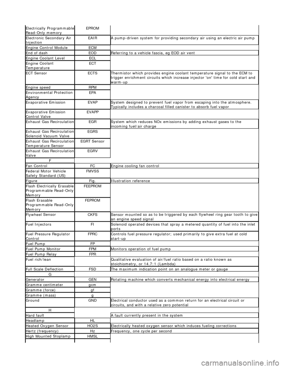
Electrically Programmable
R
ead-Only memory
EPROM
Ele
c
tronic Secondary Air
Injection
EAIRA p
ump-driven system for providing seco
ndary air using an electric air pump
Engine C
ontrol Module
ECM
End of dashEODR
e
ferring to a vehicle fascia, eg EOD air vent
Engine
C
oolant Level
ECL
Engine
C
oolant
Temperature
ECT
ECT Sen s
or
ECTSTherm
i
stor which provides engine coolant temperature signal to the ECM to
trigger enrichment circuits which increase injector 'on' time for cold start and
warm-up
Engine s
peed
RP
M
Environ m
ental Protection
Agency
EPA
Evaporative EmissionEVAPSy stem designed to prevent fu
el vapor from escaping into the atmosphere.
Typically includes a charcoal filled canister to absorb fuel vapor
Evaporative Emission
Control ValveEVAPP
Exhaust G
as Recirculation
EGRSys
t
em which reduces NOx emissions by adding exhaust gases to the
incoming fuel/air charge
Exhaus t G
as Recirculation
Solenoid Vacuum Valve
EGRS
Exhaus t G
as Recirculation
Temperature Sensor
EGRT Sen s
or
Exhaus
t G
as Recirculation
Valve
EGRV
F
F a
n Control
FCEngine
cooling fan control
F
e
deral Motor Vehicle
Safety Standard (US)
FMV S
S
Fi
gur
e
Fi
g.Illustrati
on reference
Flash
E
lectrically Erasable
Programmable Read-Only
Memory
FEE PR
OM
Flash
E
rasable
Programmable Read-Only
Memory
FEP R
OM
Flywhee
l
Sensor
CKFSSens
or moun
ted so as to be
triggered by each flywheel ring gear tooth to give
an engine speed signal
Fue l
Injectors
FISol
e
noid operated devices that spray a metered quantity of fuel into the inlet
ports
F u
el Pressure Regulator
Control
FP RCControls fuel pressure regu l
ator; used primarily to
give extra fuel at cold
start-up
Fue l
Pump
FP
Fue
l
Pump Monitor
FP
MMonitors operation of fuel pump
Fue l
Pump Relay
FP
R
Fu
el rich/lean
Q
u
alitative evaluation
of air/fuel ratio based on a ratio known as
stoichiometry, or 14.7:1 (Lambda)
F u
ll Scale Deflection
FSDTh
e
maximum indication point on
an analogue meter or gauge
G
Gene
rator
GENRot
a
ting machine which converts mechanical energy into electrical energy
G
r
amme centimeter
gcm
Gramm
e
(force)
gf
Gramm
e
(mass)
g
GroundGNDEle
c
trical conductor used
as a common return for an electrical circuit or
circuits, and with a relative zero potential
H
Hard f a
ult
A
fau
lt currently present in the system
HeadlampHL
Heat
ed Oxygen
Sensor
HO2SElectrically
h
eated oxygen sensor which induces fueling corrections
Hertz (frequency)HzFrequ
e
ncy, one cycle per second
High
Moun
ted Stoplamp
HMSL
Page 58 of 2490
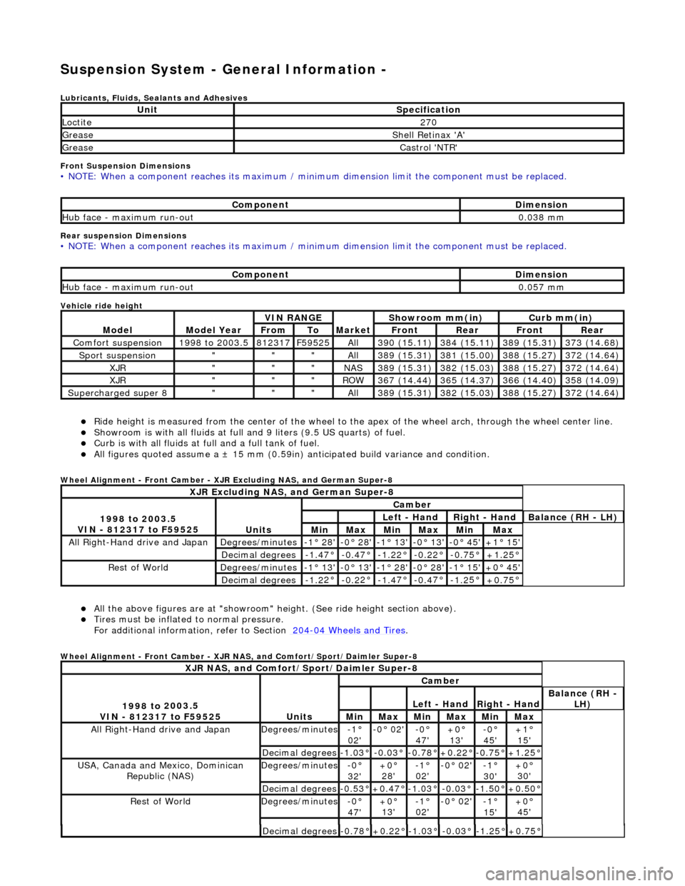
Suspension System - General Informatio
n -
Lubric
ants, Fluids, Sealants and Adhesives
Front Suspension Dimensions
• NO
TE: When a component reaches its maximum / minimum dimension limit the component must be replaced.
Rear sus
p
ension Dimensions
•
NO
TE: When a component reaches its maximum / minimum dimension limit the component must be replaced.
Vehicle ride
height
R i
de height is measured from
the center of the wheel to the apex of the wheel arch, through the wheel center line.
Showroom is with a
ll fluids at full an
d 9 liters (9.5 US quarts) of fuel.
Curb is
with all fluids at full and a full tank of fuel.
All f
i
gures quoted assume a ±
15 mm (0.59in) anticipated bu ild variance and condition.
Whee
l Alignment - Front Camber - XJR Excluding NAS, and German Super-8
Al l the above fi
gures
are at "showroom" height. (See ride height section above).
Tires must be infl
ated
to normal pressure.
For additional informat ion, refer to Section 204
-04
Wheels and Tires
.
Whe
e
l Alignment - Front Camber - XJR NAS, and Comfort/Sport/Daimler Super-8
UnitSp
ecification
Loctite27
0
Greas eShell Retin a
x 'A'
Greas
eCastro l 'NT
R'
Com
p
onent
Di
mensi
on
Hub face
-
maximum run-out
0.
03
8 mm
Com
p
onent
Di
mensi
on
Hub face
-
maximum run-out
0.
05
7 mm
Mod
e
l
Mod
e
l Year
V
I
N RANGE
Mark
et
Sh
owroom mm(in)
Curb mm(i
n)
FromToFron
t
RearFr
on
t
Rear
Com
f
ort suspension
1
998
to 2003.5
8
123
17
F
595
25
All3
90 (
15.11)
3
84 (
15.11)
3
89 (
15.31)
3
73 (
14.68)
Sport su
spe
nsion
"""All3
89 (
15.31)
3
81 (
15.00)
3
88 (
15.27)
3
72 (
14.64)
XJR"""NAS3
89 (
15.31)
3
82 (
15.03)
3
88 (
15.27)
3
72 (
14.64)
XJR"""RO
W367 (
14.44)
3
65 (
14.37)
3
66 (
14.40)
3
58 (
14.09)
Supercharged super 8"""All3
89 (
15.31)
3
82 (
15.03)
3
88 (
15.27)
3
72 (
14.64)
XJR
Excluding NAS, and German Super-8
1998 to
2003.5
VIN - 812317 to F59525
Units
Cambe r
Left
- Hand
Rig
h
t - Hand
Bal
a
nce (RH - LH)
MinMaxMinMaxMinMax
All Right-Hand driv
e and JapanDegrees
/minutes
-
1
° 28'
-0
°
28'
-
1
° 13'
-
0
° 13'
-0
° 45'+1 °
15'
Decimal degrees-1.
4
7°
-0
.4
7°
-1
.2
2°
-0.
2
2°
-0
.7
5°
+1
.25
°
R
e
st of World
De
grees
/minutes
-
1
° 13'
-0
°
13'
-
1
° 28'
-
0
° 28'
-1
° 15'+0 °
45'
Decimal degrees-1.
2
2°
-0
.2
2°
-1
.4
7°
-0.
4
7°
-1
.2
5°
+0
.75
°
XJR
NAS, and Comfort/Sport/Daimler Super-8
1
998 to
2003.5
VIN - 812317 to F59525
Units
Cambe r
Left
- Hand
Rig
h
t - Hand
Bal
a
nce (RH -
LH)
MinMaxMinMaxMinMax
All Right-Hand drive and JapanDegrees
/minutes
-1°
02'-0
° 02'
-0°
47'
+0°
13'
-0° 45'+1°
15'
Decimal degrees-1.0
3°
-0.0
3°
-0.7
8°
+0.22
°
-0.7
5°
+1.25
°
USA, Canada an
d Mexico,
Dominican
Republic (NAS)
De grees
/minutes
-0°
32 '+0 °
28'
-1 °
02'
-0 °
02'
-1°
30 '+0 °
30'
Decimal degrees-0. 5
3°
+0
.47
°
-1
.0
3°
-0
.0
3°
-1.
5
0°
+0
.50
°
R
e
st of World
De
grees
/minutes
-0°
47 '+0 °
13'
-1 °
02'
-0 °
02'
-1°
15 '+0 °
45'
Decimal degrees-0. 7
8°
+0
.22
°
-1
.0
3°
-0
.0
3°
-1.
2
5°
+0
.75
°
Page 59 of 2490
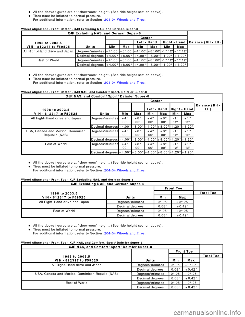
Al
l the above figures
are at "showroom" height. (See ride height section above).
Ti
res must be inflated
to normal pressure.
For additional informat ion, refer to Section 204
-0
4 Wheels and Tires
.
Whe
el Alignment - Front Castor - XJR Excluding NAS, and German Super-8
Al
l the above figures
are at "showroom" height. (See ride height section above).
Ti
res must be inflated
to normal pressure.
For additional informat ion, refer to Section 204
-0
4 Wheels and Tires
.
Whe
el Alignment - Front Castor - XJR NAS, and Comfort/Sport/Daimler Super-8
Al
l the above figures
are at "showroom" height. (See ride height section above).
Ti
res must be inflated
to normal pressure.
For additional informat ion, refer to Section 204
-0
4 Wheels and Tires
.
Whe
el Alignment - Front Toe - XJR Excluding NAS, and German Super-8
Al
l the above figures
are at "showroom" height. (See ride height section above).
Ti
res must be inflated
to normal pressure.
For additional informat ion, refer to Section 204
-0
4 Wheels and Tires
.
Whe
el Alignment - Front Toe - XJR NAS, and Comfort/Sport/Daimler Super-8
XJR
Excluding NAS, and German Super-8
1
998 to 2003.5
VIN - 812317 to F59525
Units
Castor
Le
ft - Hand
Rig
ht - Hand
Bal
ance (RH - LH)
MinMaxMinMaxMinMax
All Right
-Hand drive and Japan
De
grees/minutes
+4
° 00'
+8
° 00'
+4
° 00'
+8
° 00'
-1
° 12'
+1
° 12'
Decimal degrees+4
.00°
+8
.00°
+4
.00°
+8
.00°
-1.
20°
+1
.20°
R
est of World
De
grees/minutes
+4
° 00'
+8
° 00'
+4
° 00'
+8
° 00'
-1
° 12'
+1
° 12'
Decimal degrees+4
.00°
+8
.00°
+4
.00°
+8
.00°
-1.
20°
+1
.20°
XJR
NAS, and Comfort/Sport/Daimler Super-8
1
998 to 2003.5
VIN - 812317 to F59525
Units
Castor
Le
ft - Hand
Rig
ht - Hand
Bal
ance (RH -
LH)
MinMaxMinMaxMinMax
All Right
-Hand drive and Japan
De
grees/minutes
+4
°
00'
+8
°
00'
+4
°
00'
+8
°
00'
-1
°
12'
+1
°
12'
Decimal degrees+4
.00°
+8
.00°
+4
.00°
+8
.00°
-1.
20°
+1
.20°
USA, Canada an
d Mexico, Dominican
Republic (NAS)
De
grees/minutes
+4
°
00'
+8
°
00'
+4
°
00'
+8
°
00'
-1
°
12'
+1
°
12'
Decimal degrees+4
.00°
+8
.00°
+4
.00°
+8
.00°
-1.
20°
+1
.20°
R
est of World
De
grees/minutes
+4
°
00'
+8
°
00'
+4
°
00'
+8
°
00'
-1
°
12'
+1
°
12'
Decimal degrees+4
.00°
+8
.00°
+4
.00°
+8
.00°
-1.
20°
+1
.20°
XJR
Excluding NAS, and German Super-8
1
998 to 2003.5
VIN - 812317 to F59525
Units
Fr
ont Toe
To
tal Toe
MinMax
All Right-Hand driv
e and Japan
De
grees/minutes
0
° 05'
+0
° 25'
Decimal degrees0.
08°
+0
.42°
R
est of World
De
grees/minutes
0
° 05'
+0
° 25'
Decimal degrees0.
08°
+0
.42°
XJR
NAS, and Comfort/Sport/Daimler Super-8
1
998 to 2003.5
VIN - 812317 to F59525
Units
Fr
ont Toe
To
tal Toe
MinMax
All Right-Hand driv
e and Japan
De
grees/minutes
0
° 05'
+0
° 25'
Decimal degrees0.
08°
+0
.42°
USA, Canada an
d Mexico
, Dominican Repulic (NAS)
De
grees/minutes
0
° 05'
+0
° 25'
Decimal degrees0.
08°
+0
.42°
R
est of World
De
grees/minutes
0
° 05'
+0
° 25'
Decimal degrees0.
08°
+0
.42°
Page 60 of 2490
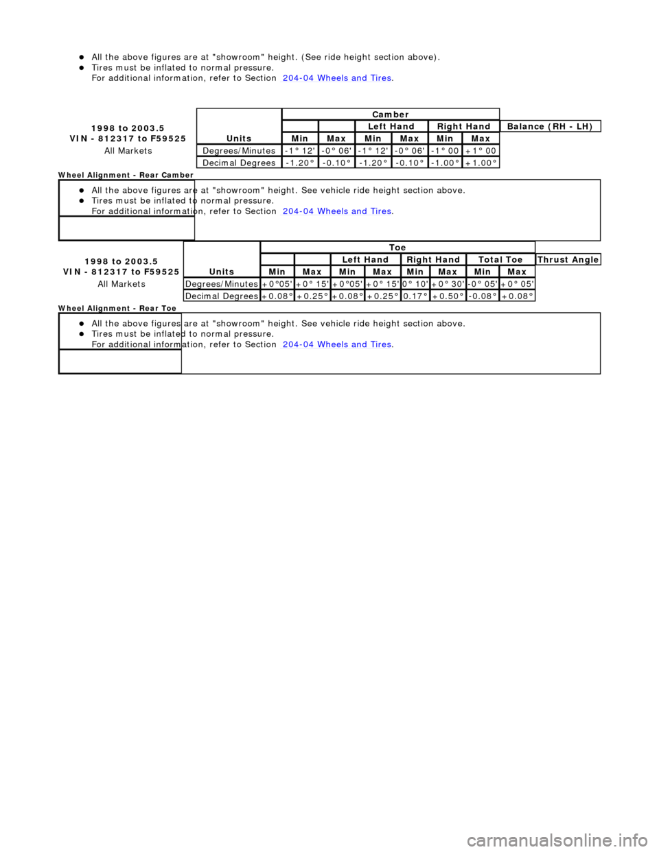
All the above fi
gures
are at "showroom" height. (See ride height section above).
Tires must be infl
ated
to normal pressure.
For additional informat ion, refer to Section 204
-04
Wheels and Tires
.
Wh
eel Alignment - Rear Camber
All the above figu res
are at "s
howroom" height. See vehicle ride height section above.
Tires must be infl
ated
to normal pressure.
For additional informat ion, refer to Section 204
-04
Wheels and Tires
.
W
h
eel Alignment - Rear Toe
All the above figu res
are at "s
howroom" height. See vehicle ride height section above.
Tires must be infl
ated
to normal pressure.
For additional informat ion, refer to Section 204
-04
Wheels and Tires
.
1 998 to
2003.5
VIN - 812317 to F59525
Units
Cambe r
Left
Hand
Rig
h
t Hand
Bal
a
nce (RH - LH)
Min MaxMin MaxMinMax
All MarketsDe
grees
/Minutes
-
1
° 12'
-0
° 06'-1° 12'-0
° 06'
-1
°
00
+1
°
00
De
ci
mal Degrees
-1.
2
0°
-0
.1
0°
-1.
2
0°
-0.
1
0°
-1.
0
0°
+1
.00
°
1
998 to
2003.5
VIN - 812317 to F59525
Units
To e
Left
Hand
Rig
h
t Hand
To
t
al Toe
Thr
u
st Angle
MinMaxMinMaxMin MaxMin Max
All MarketsDe
grees
/Minutes
+0
°
05'
+0
° 15'+0°
05'
+0
° 15'0°
10'
+0
° 30'-0° 05'+0 °
05'
De
ci
mal Degrees
+0
.08
°
+0
.25
°
+0
.08
°
+0
.25
°
0.
17
°
+0
.50
°
-0.
0
8°
+0
.08
°
Page 61 of 2490
Suspension System - General Information - Front Camber and Caster
Adjust
ment
Gen
eral Procedures
• NOTE: Before any work is commenced, th e vehicle must be checked to establish that it conforms to the Jaguar original
specification, e.g. wheels, ti res, tire pressures, etc.
• NOTE: The vehicle must be unladen and the fuel tank full when measuring suspension geometry.
1.
Road test the vehicle to establish the exact nature of the
complaint, e.g. pulling to one side, wander.
2. Measure the suspension geometry, fill in the 'Suspension
Geometry Record Form', and co ntact Jaguar Technical Support
for assistance.
3. Technical Support will give advice on the course of action to be
taken to rectify the problem.
4. Each lower wishbone pivots on and is secured to the front
crossbeam by two fulcrum bolts. A circular eccentric flange
formed under the hexagonal head of each fulcrum bolt, has
raised graduation marks to indicate radial position. A washer
with a 'D' shaped hole locates on a flat on the threaded section
of each bolt. This ensures that the washer rotates with the bolt,
maintaining an eccentric position corresponding with the
flanged head. The outer face of the washer is punch marked,
ensuring correct instal lation with the chamfered face inwards.
This permits the washer to rotate freely in the crossbeam cam
reaction plate during a djustm ent. Each fulcrum bolt and
washer are secured by a self locking nut.
On rotation of the bolt, lateral movement of the eccentric flange
and washer is restricted by the cam plate faces, forcing the bolt
shank to move laterally in the crossbeam slots. Lateral
movement of the bolt shank re sults in corresponding inward
and outward movement of th e wishbone arm, effecting
adjustment of wh eel alignment.
Rotation of the front fulcrum bolt principally adjusts wheel
caster angle, with a small amount of camber angle change.
Adjustment of the rear fulcrum bo lt mainly alters wheel camber
angle with a small amount of caster angle change.
On vehicles with VIN up to 833124, fulcrum bolt eccentric
flanges have raised graduation marks representing 15 degree
increments of bolt rotati on from 0 to 90 degrees.
On vehicles with VIN from 833125, the fulcrum bolt graduation
marks represent bolt shank ho rizontal movement in 1mm
increments from 0 to 3mm.
The upper wishbone and fulcrum shaft are not adjustable and
play no part in steering geometry adjustment.