egr JAGUAR X308 1998 2.G User Guide
[x] Cancel search | Manufacturer: JAGUAR, Model Year: 1998, Model line: X308, Model: JAGUAR X308 1998 2.GPages: 2490, PDF Size: 69.81 MB
Page 69 of 2490
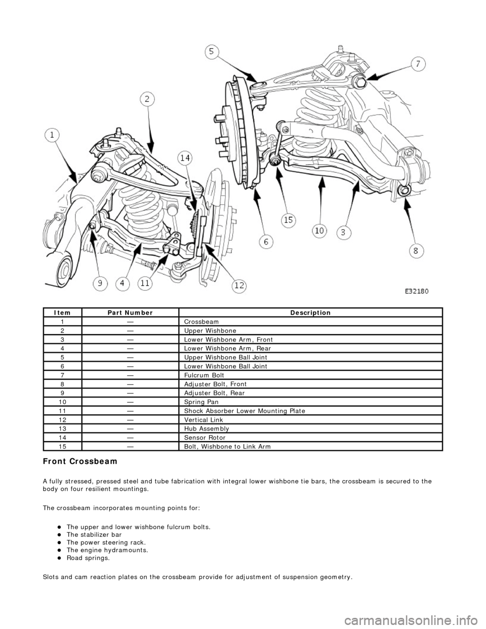
Front C
rossbeam
A
fully stressed, pressed steel and tube fa
brication with integral lower wishbone tie bars, the crossbeam is secured to the
body on four resilient mountings.
The crossbeam incorporates mounting points for:
The u
pper and lower wish
bone fulcrum bolts.
The
stabilizer bar
The power steering rack. The engine h
ydramounts.
R
oad springs.
Slots and cam reaction pl ates on the crossbeam provide for ad justment of suspension geometry.
It
em
Par
t Number
De
scription
1—Cro
ssbeam
2—Upper
Wishbone
3—Lower Wi
shbone Arm, Front
4—Lower Wi
shbone Arm, Rear
5—Upper
Wishbone Ball Joint
6—Lower Wi
shbone Ball Joint
7—Ful
crum Bolt
8—Adjuster B
olt, Front
9—Adjuster B
olt, Rear
10—S
pring Pan
11—Shock Absorber Lower M
ounting Plate
12—Vertical Link
13—Hub Assembly
14—Sensor R
otor
15—B
olt, Wishbone to Link Arm
Page 70 of 2490
Upper
Wishbones
Each
upper wi
shbone assembly is a on
e-piece steel forging incorporating:
A pres
s-fit ball joint.
Press-fi
t bushes for location of the upper fulcrum bolt.
Lower Wishbones
Each l
o
wer wishbone comprising
forged steel front and rear arms bolted together, incorporates:
A p
ress-fit ball joint in the outer extremity of the rear arm.
Press-f
i
t bushes for location of the lower fulcrum bolts
Locati
on for the shock absor
b
er lower mounting plates.
Vertica l Links
The vertical
links are of forged steel
wi
th integral steering arms. Each is suppo rted between the upper and lower wishbones
by two ball joints and carries:
Front hub
Brake ca
liper and disc shield assembly
ABS se
nsor
.
Front Hub
s
Each f
o
rged steel front hub accommodates sealed for life cartridge
type wheel bearings, and carries:
The brake rotor assembl
y.
A
h
ub nut with toothed, integral ABS rotor.
Su
s
pension spring pi
n locking device.
Front Road
Springs
The road spri
ng
s are of coil type with their
rating dependent upon vehicle specification
Ea
ch spring is installed between the suspension crossbeam location and the lower wishbone spring pan.
Ru
bber seats ar
e installed betw
een the spring and the crossb eam and the spring pan.
Front Shock A
bsorbers
Th
e
shock absorbers are telescopic hydrau
lically operated units. Optional adaptive damping units incorporate a solenoid-
operated control valve at their upper extremity.
Each shoc
k absorber is installed between the lowe
r wishbone rear arm and a recess in the body.
The l
o
wer end of the shock absorber is se
cured to plates on the wishbone by a bolt that also serves as a pivot.
The u
pper en
d of each shock absorber is secured to the body location by a single nut.
Front Sta
b
ilizer Bar
A
front stabil
izer bar installed on all vehicles
is rated according to suspension specification.
Opera
tion
As each road wheel r
i
ses, move
ment is transmitted through the vertical link assembly to the lower wishbone. The resulting
rise of the wishbone compresses the road spring and partially telescopes the shock absorber. During this action, the spring
absorbs associated shocks and the shock absorber minimizes sprin
g os c
illation.
Du
ring cornering, vehicle weight
is transferred to the outer road wheel with a resulting tendency for the inner wheel to lift.
The stabilizer bar assists in minimizing this tendency by transf erring a proportion of potential lift of the inner wheel to the
outer wheel. This result s in enhanced body stability with improved corner ing capabilities.
Page 138 of 2490

In
stallation
1.
Position the vertical link so that inboard side of the
bearing bore is resting on suitable supports on the
press-bed.
2. Position special tool 204-197 on top of bearing.
3. Operate press to remove bearing from vertical link,
discard bearing.
11. Clean relevant parts.
1. NOTE : Th
e gap between the ears of the circlip must be
positioned so that it is in the lowest position of the bore when the
vertical link is installed on the vehicle. Refer to General
Procedures for further information.
Install outboard circlip in vertical link.
2. Using a h y
draulic press, install
bearing in the vertical link.
1. Position vertical link on the press bed with outboard
side of the vertical link face down.
2. Position bearing on vertical link.
3. Position special tool on top of wheel bearing.
4. Operate press to install be aring, applying a three-ton
load to ensure that the bearing is fully seated.
3. CAUTIO
N: To prevent damage to the integral wheel-
bearing seal, select circlip plier en ds that do not protrude through
the circlip ears.
4. NOTE : Th
e gap between the ears of the circlip must be
positioned so that it is in the lowest position of the bore, when the
vertical link is installed on the vehicle. Refer to General
Procedures for further information.
Page 144 of 2490

In
stallation
the vertical li
nk.
13 . N
OTE: Ensure
the vertical link is level, and the supports are
situated as near to the bearing bore as possible.
Using a hydraulic press, remove wheel bearing from the vertical
link.
1. Position the vertical link so that the inboard side of the bearing bore is resting on suit able supports on
the press-bed.
2. Position special tool 204-197 on top of bearing.
3. Operate press to remove bearing from vertical link,
discard bearing.
14. Clean relevant parts.
1. NOTE : Th
e gap between the ears of the circlip must be
positioned so that it is in the lowest position of the bore when the
vertical link is installed on the vehicle. Refer to General
Procedures for further information.
Install outboard circlip in vertical link.
2. Usi ng a h
ydraulic press, install wheel bearing in vertical link.
1. Position vertical link on the press bed with outboard
side of the vertical link face down.
2. Position wheel bearing on vertical link.
3. Position special tool on top of wheel bearing.
4. Operate press to install be aring, applying a three-ton
seating load to ensure the bearing is fully seated.
3. CAUTION: To prevent damage to the integral bearing
seal, select circlip plier ends th at do not protrude through the
circlip ears.
Page 150 of 2490

In
stallation
Using a hy
draulic press, remove
wheel bearing from the vertical
link.
1. Position the vertical link so that the inboard side of the bearing bore is resting on suit able supports on
the press-bed.
2. Position special tool on top of bearing.
3. Operate press to remove bearing from vertical link,
discard bearing.
14. Clean relevant parts.
1. NOTE : Th
e gap between the ears of the circlip must be
positioned so that it is in the lowest position of the bore when the
vertical link is installed on the vehicle. Refer to General
Procedures for further information.
Install outboard circlip in vertical link.
2. Using a h y
draulic press, instal
l bearing in vertical link.
1. Position vertical link on the press bed with outboard
side of the vertical link face down.
2. Position wheel bearing on vertical link.
3. Position special tool on top of wheel bearing.
4. Operate press to install the bearing, applying a three- ton seating load to ensure bearing is fully seated.
3. CAUTIO
N: To prevent damage to the integral bearing
seal, select circlip plier ends th at do not protrude through the
circlip ears.
4. NOTE : Th
e gap between the ears of the circlip must be
positioned at the lowest point of the bore, when the vertical link is
installed on the vehicl e. Refer to General Procedures for further
information.
Page 168 of 2490
Each r
oad spring and is located between the wishbone in
tegral spring seat and the body suspension turret.
Each shoc
k absorber unit is installed
co-axially within the road spring.
The lo
wer end of each shock absorber is secured to the
wishbone by a bolt which also functions as a pivot.
Adaptive damping is av
ailable as an option.
A
rear stabi
lizer bar is installed on
Supercharged and Sport Suspension models . Mounted at the rear of the wishbone
tie assembly, the stabilizer bar is connected to the wishbone by short links.
Op era
tion
As each road wheel r
i
ses, move
ment is transmitted through th e hub carrier assembly to the wishbone and axle shaft. The
corresponding rise of the wishbone compre sses the road spring and partially telescopes the shock absorber. During this
action, the spring absorbs result ing shocks and the shock absorber minimizes spring oscillation.
During cornering, vehicle weight is transferred to the outer road wheel with a resulting tendency for the inner wheel to lift.
On Supercharged and Sport Suspension vehicl es, a rear stabilizer bar assists in minimizing this tendency by transferring a
proportion of potential lift of the inner wheel to the outer wheel. This results in enhanced body stability with improved
cornering capabilities.
Page 278 of 2490
Vehicle Dynamic Suspension - Vehicle Dynamic Suspension
Diagn
osis and Testing
Refer to the PDU User Guide for details of diagnosing and testing the Adaptive Damping System. The PDU interrogates the
ADCM directly via the K and L lines to the J1962 diagnostic socket.
The PDU will give an indication of the integrity of each electron ic and electrical component. It will indicate, for example, that
the accelerometers are not broken, but not that they functionin g correctly when the vehicle is in motion. However, it is
exceptional for an accelero meter to function incorrectly in its dynamic mode if it is proved to be functioning when static.
Basic Checks
The accele
rometers have the following ch
aracteristics. At 0g (no movement of the body) each vertical accelerometer
outputs approximately 2.5V steady voltage; the lateral acce lerometer outputs approximately 1.5V. The voltage output due
to body movement is proportional to acceleration in the acceleration axis, up to approximately 4.5V and down to
approximately 0.5V.
Before changing any component, refer to the circuit diagrams and check the cont inuity of relevant harness circuits; in some
instances, the PDU will not different iate between a faulty component an d a damaged connection or wiring.
Check the following fuses:
En
gine compartment fuse
box, fuse F5 (10A).
Engine m
anagement fuse
box, fuse F1 (20A).
Check the following ADCM input/output lines:
Sy stem erro
r output from the ADCM
to the instrument cluster.
Vehicl
e speed output from the inst
rument cluster to the ADCM.
Foo
tbrake signal to the ADCM.
Check any relevant connections to confirm that the connection is electrically sound and that a terminal pin has not been
pushed back into the connector shell, ie. not ma king a connection to its mating pin or socket.
Page 285 of 2490
R
ear Drive Axle/Differential - Rear Drive Axle and Differential
Description an
d Operation
Loca
tion
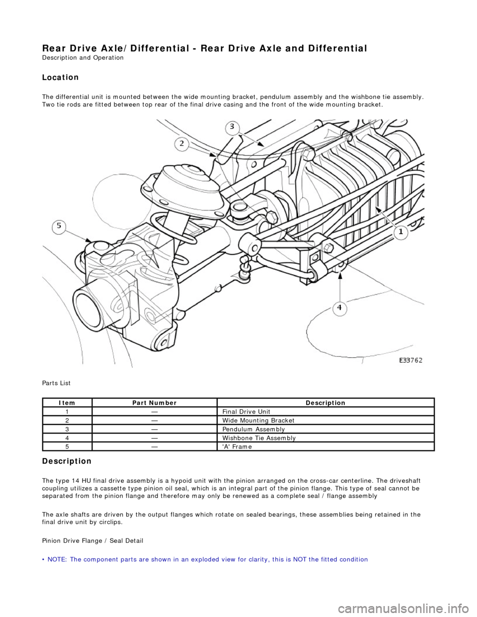
The differential
unit
is mounted between the wide mount ing bracket, pendulum assembly and the wishbone tie assembly.
Two tie rods are fitted between top rear of the final dr ive casing and the front of the wide mounting bracket.
Parts List
Description
The
type 14 HU final drive assembly is a hypoid unit with th
e pinion arranged on the cross-car centerline. The driveshaft
coupling utilizes a cassette type pinion oil seal, which is an in tegral part of the pinion flange. This type of seal cannot be
separated from the pinion fl ange and therefore may only be renewed as a complete seal / flange assembly
The axle shafts are driven by the output flanges which rotate on sealed bearings , these assemblies being retained in the
final drive unit by circlips.
Pinion Drive Flange / Seal Detail
• NOTE: The component parts are shown in an exploded view for clarity, this is NOT the fitted condition
It
em
Par
t Number
De
scription
1—F
inal Drive Unit
2—W
ide Mounting Bracket
3—Pen
dulum Assembly
4—Wi
shbone Tie Assembly
5—'A'
Frame
Page 431 of 2490
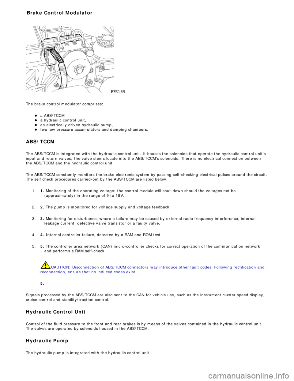
The brake
control modulator comprises:
a A
BS/TCCM
a h
ydraulic control unit,
an electrically driven hydrau
lic pump,
two low pressure accumulato
rs and damping chambers.
ABS/TCCM
The AB
S/TCCM is integrated with the hydrau
lic control unit. It houses the solenoids that operate the hydraulic control unit's
input and return valves; the valve stems locate into the ABS/TCCM's solenoids. There is no electrical connection between
the ABS/TCCM and the hydraulic control unit.
The ABS/TCCM constantly monitors the brake electronic system by passing self-checking electrical pulses around the circuit.
The self check procedures carried-out by the ABS/TCCM are listed below:
1. 1. Monitoring of the operating voltage: the control mo dule will shut-down should the voltages not be
(approximately) in the range of 9 to 19V.
2. 2. The pump is monitored for volt age supply and voltage feedback.
3. 3. Monitoring for disturbance, where a failure may be caus ed by external radio frequency interference, internal
leakage current, defective valve transistor or a faulty valve.
4. 4. Internal controller failure, de tected by a RAM and ROM test.
5. 5. The controller area network (CAN) micr o-controller checks for correct operation of the communication network
and performs a RAM self-check.
CAUTION: Disconnection of ABS/TCCM connectors may introduce other fault codes. Following rectification and
reconnection, ensure that no induced codes exist.
5.
Signals processed by the ABS/TCCM are also sent to the CAN for vehicle use, such as the instrument cluster speed display,
cruise control and stability/traction control.
Hydraulic Control Unit
Control of
the fluid pressure to
the front and rear brakes is by means of the valves contained in the hydraulic control unit.
The valves are operated by solenoids housed in the ABS/TCCM.
Hydraulic Pump
The
hydraulic pump is integrated
with the hydraulic control unit.
Bra
ke Control Modulator
Page 439 of 2490
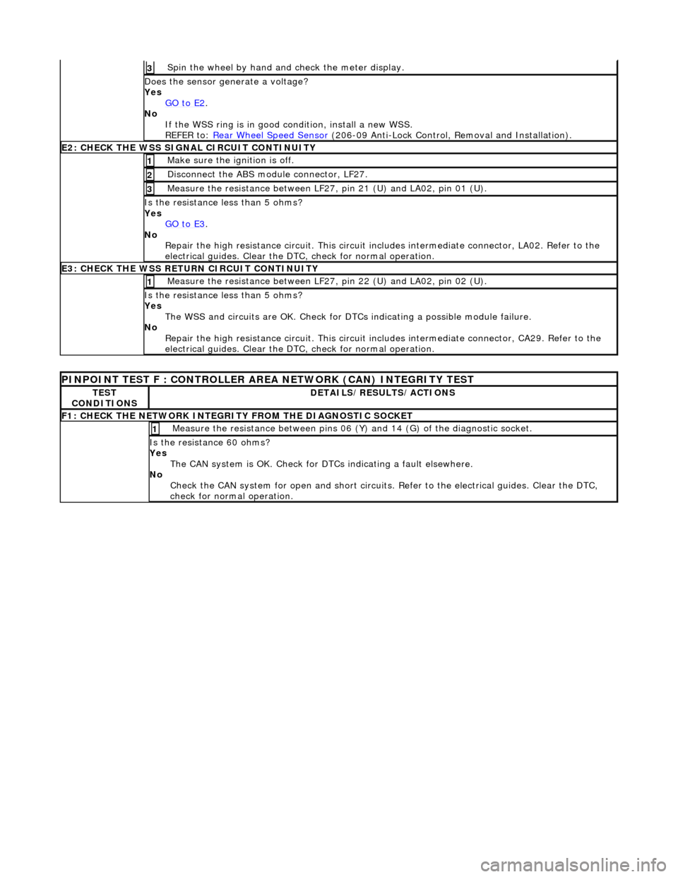
Spin
the wheel by hand and check the meter display.
3
Doe
s the sensor generate a voltage?
Yes GO to E2
.
No
If the WSS ring is in good condition, install a new WSS.
REFER to: Rear Wheel Speed Sensor
(20
6-09 Anti-Lock Control, Removal and Installation).
E2
: CHECK THE WSS SIGNAL CIRCUIT CONTINUITY
Make sure the ignition is off. 1
Di
sconnect the ABS module connector, LF27.
2
Meas
ure the resistance between LF27
, pin 21 (U) and LA02, pin 01 (U).
3
I
s the resistance less than 5 ohms?
Yes GO to E3
.
No
Repair the high resistance circui t. This circuit includes intermediate connector, LA02. Refer to the
electrical guides. Clear the DTC, check for normal operation.
E3
: CHECK THE WSS RETURN CIRCUIT CONTINUITY
Meas
ure the resistance between LF27
, pin 22 (U) and LA02, pin 02 (U).
1
I
s the resistance less than 5 ohms?
Yes The WSS and circuits are OK. Check for DTCs indicating a possible module failure.
No Repair the high resistance circui t. This circuit includes intermediate connector, CA29. Refer to the
electrical guides. Clear the DTC, check for normal operation.
P
INPOINT TEST F : CONT
ROLLER AREA NETWORK (CAN) INTEGRITY TEST
TE
ST
CONDITIONS
D
ETAILS/RESULTS/ACTIONS
F
1: CHECK THE NETWORK INTEGRITY
FROM THE DIAGNOSTIC SOCKET
M
easure the resistance between pins 06 (Y) and 14 (G) of the diagnostic socket.
1
I
s the resistance 60 ohms?
Yes The CAN system is OK. Check for DTCs indicating a fault elsewhere.
No Check the CAN system for open an d short circuits. Refer to the electrical guides. Clear the DTC,
check for normal operation.