egr JAGUAR X308 1998 2.G Owner's Manual
[x] Cancel search | Manufacturer: JAGUAR, Model Year: 1998, Model line: X308, Model: JAGUAR X308 1998 2.GPages: 2490, PDF Size: 69.81 MB
Page 480 of 2490

The steering rack assembly :
Is mounted on the
rear face of the
front suspension crossbeam by two forg ed mounting brackets with resilient
bushes. The bushes are handed (pinion side and non-pinion side) and are orientated according to the vehicle range
application.
Convert s
the rotary motion of the steering wheel, via the steering gear pinion, to the lateral motion of the rack.
F
e
atures a variable ratio steering
rack with integral hydraulic po wer steering cylinder and piston.
Has a hydrauli
c control valve with Servotronic co
ntrol and positive center feel torsion bar.
The basic steering rack assembly is not serviceable. The following components are serviceable items:
Transfer pipework
.
Servotronic valve. Cent
ralizing cap.
O
u
ter ball joint.
Rac
k
gaiter.
Clips and
fittings.
Steering Rack Components
It e
m
Par
t
Number
De
scr
iption
1—Front
su
spension crossbeam
2—Steeri
ng rack housi
ng
3—Hydraulic
control valve housing
4—Moun
ting bracke
t
5—Gait
er
6—Tie
rod
7—O
u
ter ball joint
Steering R
a
ck Assembly
Page 483 of 2490

P
arts List
The positive center-feel torsion bar improves the straight ahead feel of the steering in the region where very small amounts
of hydraulic pressure, and hence re action pressure, are generated.
The torsion bar assembly forms part of the hydraulic control valve assembly , and includes an axially pre-loaded metal
bellows spring, which is arranged co-axially with the torsion bar. The torsion bar is positively connected between the end
piece and the input shaft. One end of the bellows spring is attached to the input shaft, while the other end is attached to a
centering device. The centering device has two prism-shaped recesses with ca ged, guided, ball bearings arranged between
the recesses, and determines the zero-torsion position of the bellows spring.
On turning the steering wheel from the straight ahead position, the spring fo rces of the torsion bar assembly must be
overcome. Initially, the bellows spring produces substantial additional torsional resistance. However, after an angular
movement of approximately 0.2 degrees the torsional rigidity decreases and becomes similar to a conventional torsion bar.
It
em
Par
t Number
De
scription
1—End piece
2—Torsio
n bar
3—Caged ball bearing
s
4—Centering device
5—Bel
lows spring
6—In
put shaft
Positive Center-Feel Torsion Bar
Torsio
n Bar Components
Page 485 of 2490

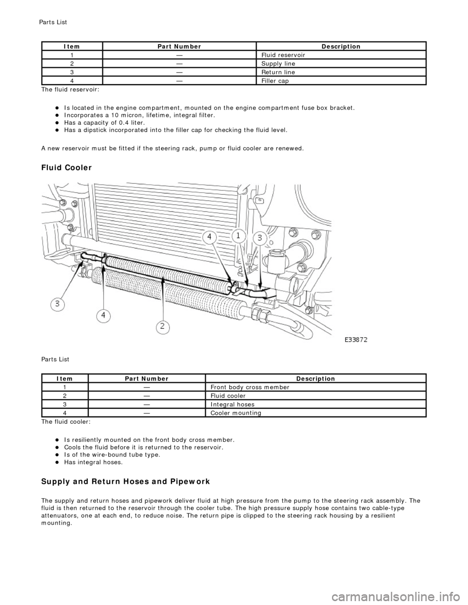
The fluid reservo
ir:
Is lo
cated in the engine compartment, mounted on the engine compartment fuse box bracket.
Incorporates
a 10 micron, li
fetime, integral filter.
Has a cap
acity of 0.4 liter.
Has a dipsti
ck incorporated into the filler cap for checking the fluid level.
A new reservoir must be fitted if the steering rack, pump or fluid cooler are renewed.
Fluid C
ooler
P
arts List
The fluid cooler:
Is
resiliently mounted on th
e front body cross member.
Coo
ls the fluid before it is
returned to the reservoir.
Is
of the wire-bound tube type.
Has i
ntegral hoses.
Supply and Return Hoses a
nd Pipework
The supply and return h
oses and
pipework deliver fluid at high pressure from the pump to th e steering rack assembly. The
fluid is then returned to th e reservoir through the cooler tube. The high pressure supply hose contains two cable-type
attenuators, one at each end, to reduce nois e. The return pipe is clipped to the steering rack housing by a resilient
mounting.
It
em
Par
t Number
De
scription
1—Fl
uid reservoir
2—Supply line
3—R
eturn line
4—Fi
ller cap
It
em
Par
t Number
De
scription
1—Front body cross member
2—F
luid cooler
3—Inte
gral hoses
4—Cooler m
ounting
P
arts List
Page 503 of 2490

Steering
Linkage - Steering Linkage
Descriptio
n and Operation
Parts List
The left- and right-hand tie rod assemblies:
T
ransmit steering forces from the steering rack to the st
eering arms which are integral with the vertical links.
Comprise the tie rod, inner
ball joint,
outer tie rod end and outer ball joint.
P
rovide front road wheel toe setting by adju
stment of the threaded outer tie rod ends.
• NOTE: Steering geometry adjustments must only be carried out wi th the vehicle on turn plates to allow the wheels to move
during adjustment.
The left- and right-hand steering rack gaiters:
Are
installed between the steering rack and the tie bars.
Are
of the concertina type.
R
etain lubricant and prevent th
e ingress of foreign matter.
P
ermit movement of the steering rack and tie rods.
ItemPa
rt Number
Descript
ion
1—St
eering rack assembly
2—St
eering rack gaiter
3—I
nner ball joint
4—Tie
rod
5—O
uter tie rod end
6—Lo
ck-nut
7—Oute
r ball joint
8—O
uter ball joint nut
Page 521 of 2490

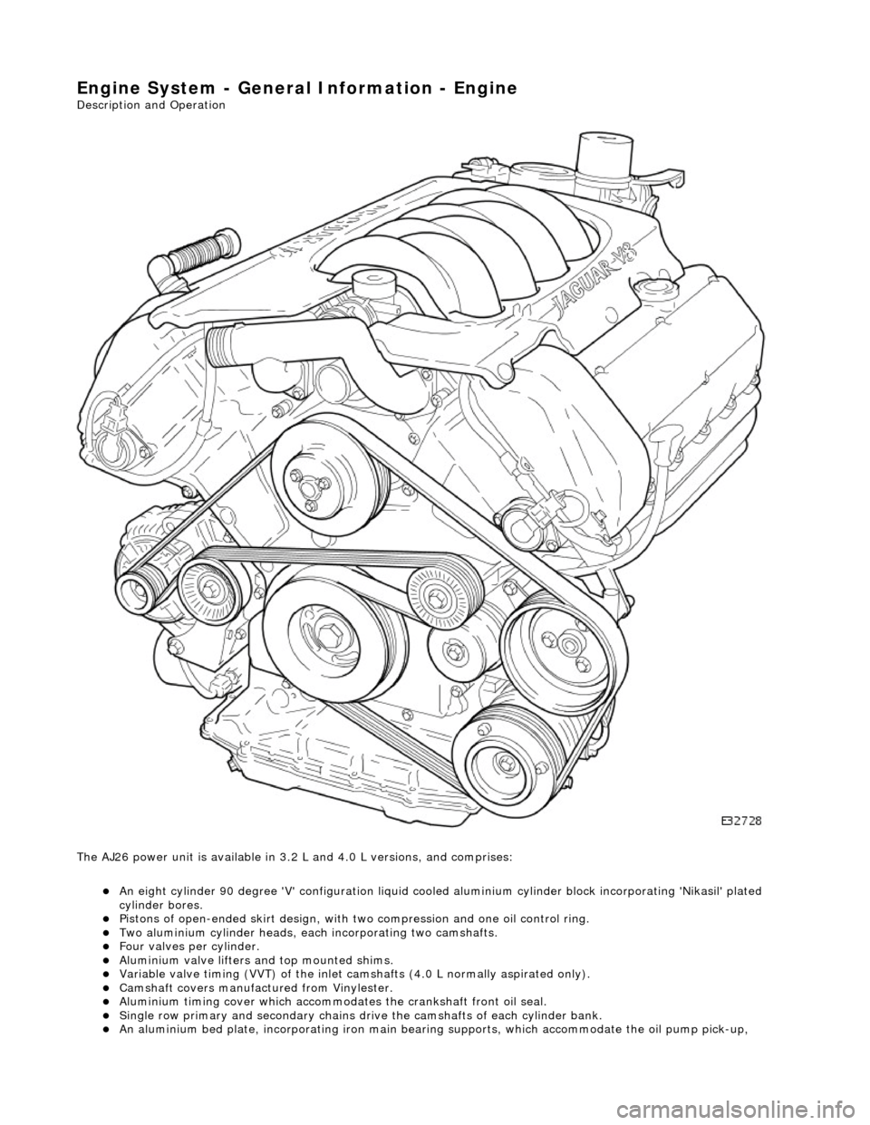
Engine System - General Infor
mation - Engine
Description an
d Operation
The AJ26 power unit is available in 3.2 L and 4.0 L versions, and comprises:
An eight cylinder 9
0 degree 'V' config
uration liquid cooled aluminium cylinder block incorporating 'Nikasil' plated
cylinder bores.
Pi
stons of open-ended skirt design, with
two compression and one oil control ring.
Two al
uminium cylinder heads, each
incorporating two camshafts.
F
our valves per cylinder.
Al
uminium valve lifters and top mounted shims.
Vari
able valve timing (VVT) of the inlet camshafts (4.0 L normally aspirated only).
Camshaft
covers manufactured from Vinylester.
Al
uminium timing cover which accommodat
es the crankshaft front oil seal.
Sin
gle row primary and secondary chains dr
ive the camshafts of each cylinder bank.
An alu
minium bed pl
ate, incorporating iron main bearing supports, which accomm odate the oil pump pick-up,
Page 528 of 2490

Speed an
d load
Coo
l
ant temperature
Ti
me el
apsed from start up
Cl
osed l
oop fuelling
Determination of the vapour concentration is made by stepped opening of the EVAP valve and subsequent monitoring of the
fuelling correction. This function is performed prior to purging, so that at the onse t of purging the EVAP valve can be set to
the optimum position. Should the ECM be unable to determine the concentration before purging, a default value is
employed, which is then modified whilst purging is in progress.
When the purging process is operational th e ECM modifies the basic fuelling calculation to maintain the correct air / fuel
ratio.
Purging is inhibited during fuel cut-off and stability / traction control intervention.
Coolant Temperature Sen
sor
Th
e
sensor outputs a voltage to the ECM which decreases as temperature increases.
Cooling Fans
In response to engi
ne coolant temperat
u
re and climate control system demand, the ECM will energize the cooling fans.
Climate Control Compressor
The E
C
M will allow the compressor clutch to be engaged if th
e engine temperature and load demand are normal. Should the
driver require maximum engine powe r or the coolant temperature be high, the request will be denied.
Cranking Signal
The ECM reacts to a signal fr
om th
e Body Processor Module (BPM) when the starter motor relay is energi
zed. This signal is
used to trigger starting, fu el and ignition strategies.
Engine Speed and Cranksh
aft Position
Engine
speed and cran
k position are moni
tored by a sensor which is mounted on the cylinder block (flywheel housing)
behind the crankshaft drive plat e. It indicates rotational speed to the ECM in the form of 12 pulses per crank revolution.
Engine speed is used for synchronization of fuel an d ignition systems, as well as other functions.
Camshaft Position
The ca
mshaft position sensor is mounted at
the rear of Bank 2 cylinder head on the inlet side and provides one signal every
720 degrees of crankshaft rotation. The signal, in conjunction with the signal from the crankshaft position sensor, indicates
to the ECM that the piston of cylinder 1A is approaching TDC on the compression stroke.
Variable Valve
Timing (Where Fitted)
By energi
si
ng a solenoid to allow the pass
age of pressurized oil on each of the inle t camshaft drives, the ECM can vary by a
single stepped amount, the relati ve timing of the inlet valves.
Ign
ition
Ignit
i
on spark is produced by
individual on-plug coil units.
There are two ignition amplifiers; module #1 drives coils 1A, 2B, 3B and 4A, whilst module #2 drives coils 1B, 2A, 3A and
4B. The ECM controls the amplifiers.
Page 529 of 2490

Thi
s sensor uses a piezo-electric sensing element to detect kn
ock which may occur under acceleration at critical conditions.
Should detonation be present the ECM will retard ignition timing of individual cylinders.
Exhaust G
as Recirculation
The EGR
valve (where fitted) reduces NOx
emissions by recirculating a portion of the exhaust gases back into the inlet
manifold.
Heated Oxyg
en Sensors
The h
eated oxygen sensors, one per bank, are situated upstream of the catalysts. Integral
to the sensors are heaters
(under ECM control) which allow the sensor s to reach their operating temperature as soon as possible after engine start. A
comparison between the level of oxygen in the exhaust gas to that in the atmosphere produces an output signal. This signal
is used by the engine closed loop fuel strategy to make fuelling corrections and so control overall emission levels.
Oxygen Sensors
Thes
e sensors, one per bank, are situated downstream of the
catalyst. The comparison of upstream and downstream signals
allows determination of cata lyst conversion efficiency.
Knock Sensor
Page 683 of 2490

Engine - Exhaust Manifold RH
In-vehicle Repair
Removal
1. Open the engine compartment and fit paintwork protection
sheets.
2. Remove the air cleaner assemb ly. Refer to Section 303-12.
3. Remove the front silencer. Refer to Section 309-00.
4. Remove the downpipe catalytic converter, right hand side.
Refer to Section 309-00.
5. From above the vehicle, disconnect the EGR pipe from the
exhaust manifold.
1. Remove the two nuts whic h secure the EGR flange to
the right hand exhaust manifold.
2. Reposition the EGR pipe from the manifold.
6. Remove the bolts which secure th e front section of the exhaust
manifold to the cylinder head.
7. If working on a right hand drive vehicle; reposition the steering rack for access.
1. Remove the two bolts which secure the steering rack at the passenger side.
2. Loosen, but do not remove, the two bolts which secure the steering rack at the driver's side.
Reposition the steering rack for access.
8. Working from below the vehicle, remove the manifold bolts.
1. Remove the bolts which secu re the rear section of the
exhaust manifold to the cylinder head.
Page 684 of 2490

Installation
9. Remove the manifold.
1. Remove the manifold and the manifold gasket from the cylinder head.
2. Remove the gasket from the EGR flange.
10. If fitting a new manifold, remove the two studs from the EGR
flange of the manifold. and transfer them to the new manifold.
11. Clean the manifold faces (if refi tting) and the mating faces on
the cylinder head.
12. Use a thread tap (plug) to clean out the threads of the
manifold securing bolt holes, in the cylinder head.
1. Fit a spacer to each new manifo ld securing bolt (8 bolts).
2. Fit the manifold and manifold gasket.
1. Fit and align the new gasket to the cylinder head.
2. Fit and align the manifo ld to the cylinder head.
3. Fit the rear four bolts wh ich secure the manifold, but
do not tighten.
3. Working from above the vehicle, fit and tighten the remaining
manifold securing bolts.
4. Working from below the vehicle, fu lly tighten the rear bolts on
each manifold.
5. Refit the steering rack (if removed for access).
1. Reposition th e steering rack.
2. Fit and tighten the rack mounting bolts on the passenger side.
Page 685 of 2490

3. Tighten the rack mounting bolts on the driver's side.
6. From above the vehicle, connect the EGR pipe to the exhaust
manifold.
1. Fit a new EGR gasket to the manifold.
2. Reposition the EGR pipe to the manifold.
3. Fit the two nuts which secure the EGR flange to the exhaust manifold.
7. Fit the downpipe catalytic converter, right hand side. Refer to
Section 309-00.
8. Fit the front silencer. Refer to Section 309-00.
9. Fit the air cleaner assembly . Refer to Section 303-12.
10. Remove paintwork protection sheets and close the engine
compartment.