egr JAGUAR X308 1998 2.G Owner's Guide
[x] Cancel search | Manufacturer: JAGUAR, Model Year: 1998, Model line: X308, Model: JAGUAR X308 1998 2.GPages: 2490, PDF Size: 69.81 MB
Page 686 of 2490

Engine - Exhaust Manifold LH and RH
In-vehicle Repair
Removal
1. Open the engine compartment and fit paintwork protection
sheets.
2. Remove the downpipe catalytic converter, right hand side.
Refer to Section 309-00.
3. Remove the downpipe catalytic co nverter, left hand side. Refer
to Section 309-00.
4. Remove the front silencer. Refer to Section 309-00.
5. Remove the air cleaner assemb ly. Refer to Section 303-12.
6. Working from above the vehicl e, remove the bolts which
secure the front sectio n of the left hand exhaust manifold to
the cylinder head.
7. Working from below the vehicle, reposition the steering rack
for access.
1. Remove the two bolts which secure the steering rack at the driver's side.
2. Loosen, but do not remove, the two bolts which secure the steering rack at the passenger side.
Reposition the steering rack for access.
8. Working from below the vehicl e, remove the manifold.
1. Remove the bolts which secu re the rear section of the
exhaust manifold to the cylinder head.
2. Remove the manifold and the manifold gasket.
9. From above the vehicle, disconnect the EGR pipe from the
right hand exhaust manifold.
1. Remove the two nuts whic h secure the EGR flange to
the right hand exhaust manifold.
2. Reposition the EGR pipe from the manifold.
Page 687 of 2490

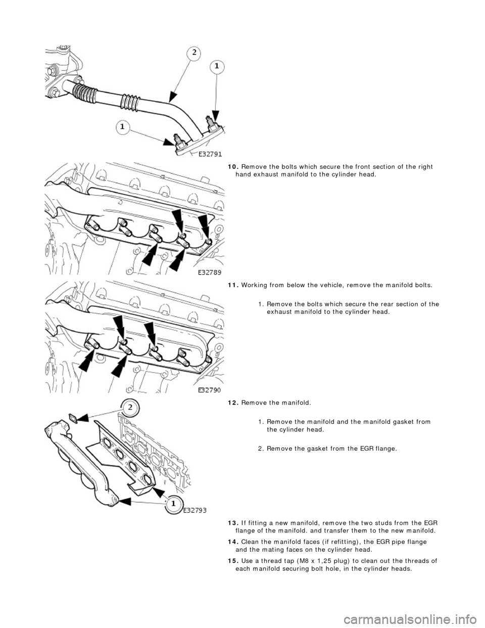
10. Remove the bolts which secure the front section of the right
hand exhaust manifold to the cylinder head.
11. Working from below the vehicle, remove the manifold bolts.
1. Remove the bolts which secu re the rear section of the
exhaust manifold to the cylinder head.
12. Remove the manifold.
1. Remove the manifold and the manifold gasket from the cylinder head.
2. Remove the gasket from the EGR flange.
13. If fitting a new manifold, remove the two studs from the EGR
flange of the manifold. and transfer them to the new manifold.
14. Clean the manifold faces (if refitting), the EGR pipe flange
and the mating faces on the cylinder head.
15. Use a thread tap (M8 x 1,25 plug) to clean out the threads of
each manifold securing bolt hole, in the cylinder heads.
Page 688 of 2490

Installation
1.
Use new manifold securing bolt s and.fit a spacer to each.
2. Fit each manifold and manifold gasket.
1. Fit and align the new gasket to the cylinder head.
2. Fit and align the manifo ld to the cylinder head.
3. Fit the rear four bolts wh ich secure the manifold, but
do not tighten.
3. Working from above the vehicle, fit and tighten the remaining
manifold securing bolts.
4. Working from below the vehicle, fu lly tighten the rear bolts on
each manifold.
5. Refit the steering rack.
1. reposition the steering rack.
2. Fit and tighten the rack mounting bolts on the driver's
side.
3. Tighten the rack mounting bolts on the passenger side.
6. From above the vehicle, connect the EGR pipe to the right
hand exhaust manifold.
1. Fit a new EGR gasket to the manifold.
2. Reposition the EGR pipe to the manifold.
3. Fit the two nuts which secure the EGR flange to the exhaust manifold.
7. Fit the downpipe catalytic converter, left hand side. Refer to
Section 309-00.
8. Fit the downpipe catalytic converter, right hand side. Refer to
Section 309-00.
9. Fit the front silencer. Refer to Section 309-00.
10. Fit the air cleaner assembly . Refer to Section 303-12.
11. Remove paintwork protection sheets and close the engine
compartment.
Page 690 of 2490

Engine - Exhaust Manifold Gasket RH
In-vehicle Repair 1. Open the engine compartment and fit paintwork protection
sheets.
2. Remove the air cleaner assemb ly. Refer to Section 303-12.
3. Remove the front silencer. Refer to Section 309-00.
4. Remove the downpipe catalytic converter, right hand side.
Refer to Section 309-00.
5. From above the vehicle, disconnect the EGR pipe from the
exhaust manifold.
1. Remove the two nuts whic h secure the EGR flange to
the right hand exhaust manifold.
2. Reposition the EGR pipe from the manifold.
6. Remove the bolts which secure th e front section of the exhaust
manifold to the cylinder head.
7. If working on a right hand drive vehicle; reposition the steering rack for access.
1. Remove the two bolts which secure the steering rack at the passenger side.
2. Loosen, but do not remove, the two bolts which secure the steering rack at the driver's side.
Reposition the steering rack for access.
8. Working from below the vehicle, remove the manifold bolts.
1. Remove the bolts which secu re the rear section of the
exhaust manifold to the cylinder head.
Page 691 of 2490

Installation
9. Remove the manifold.
1. Remove the manifold and the manifold gasket from the cylinder head.
2. Remove the gasket from the EGR flange.
10. If fitting a new manifold, remove the two studs from the EGR
flange of the manifold. and transfer them to the new manifold.
11. Clean the manifold faces (if refi tting) and the mating faces on
the cylinder head.
12. Use a thread tap (plug) to clean out the threads of the
manifold securing bolt holes, in the cylinder head.
1. Fit a spacer to each new manifo ld securing bolt (8 bolts).
2. Fit the manifold and manifold gasket.
1. Fit and align the new gasket to the cylinder head.
2. Fit and align the manifo ld to the cylinder head.
3. Fit the rear four bolts wh ich secure the manifold, but
do not tighten.
3. Working from above the vehicle, fit and tighten the remaining
manifold securing bolts.
4. Working from below the vehicle, fu lly tighten the rear bolts on
each manifold.
5. Refit the steering rack (if removed for access).
1. Reposition th e steering rack.
2. Fit and tighten the rack mounting bolts on the passenger side.
Page 692 of 2490

3. Tighten the rack mounting bolts on the driver's side.
6. From above the vehicle, connect the EGR pipe to the exhaust
manifold.
1. Fit a new EGR gasket to the manifold.
2. Reposition the EGR pipe to the manifold.
3. Fit the two nuts which secure the EGR flange to the exhaust manifold.
7. Fit the downpipe catalytic converter, right hand side. Refer to
Section 309-00.
8. Fit the front silencer. Refer to Section 309-00.
9. Fit the air cleaner assembly . Refer to Section 303-12.
10. Remove paintwork protection sheets and close the engine
compartment.
Page 693 of 2490

Engine - Exhaust Manifold Gasket LH and RH
In-vehicle Repair
1. Open the engine compartment and fit paintwork protection
sheets.
2. Remove the downpipe catalytic converter, right hand side.
Refer to Section 309-00.
3. Remove the downpipe catalytic co nverter, left hand side. Refer
to Section 309-00.
4. Remove the front silencer. Refer to Section 309-00.
5. Remove the air cleaner assemb ly. Refer to Section 303-12.
6. Working from above the vehicl e, remove the bolts which
secure the front sectio n of the left hand exhaust manifold to
the cylinder head.
7. Working from below the vehicle, reposition the steering rack
for access.
1. Remove the two bolts which secure the steering rack at the driver's side.
2. Loosen, but do not remove, the two bolts which secure the steering rack at the passenger side.
Reposition the steering rack for access.
8. Working from below the vehicl e, remove the manifold.
1. Remove the bolts which secu re the rear section of the
exhaust manifold to the cylinder head.
2. Remove the manifold and the manifold gasket.
9. From above the vehicle, disconnect the EGR pipe from the
right hand exhaust manifold.
1. Remove the two nuts whic h secure the EGR flange to
the right hand exhaust manifold.
2. Reposition the EGR pipe from the manifold.
Page 694 of 2490

10. Remove the bolts which secure the front section of the right
hand exhaust manifold to the cylinder head.
11. Working from below the vehicle, remove the manifold bolts.
1. Remove the bolts which secu re the rear section of the
exhaust manifold to the cylinder head.
12. Remove the manifold.
1. Remove the manifold and the manifold gasket from the cylinder head.
2. Remove the gasket from the EGR flange.
13. If fitting a new manifold, remove the two studs from the EGR
flange of the manifold. and transfer them to the new manifold.
14. Clean the manifold faces (if refitting), the EGR pipe flange
and the mating faces on the cylinder head.
15. Use a thread tap (M8 x 1,25 plug) to clean out the threads of
each manifold securing bolt hole, in the cylinder heads.
Page 695 of 2490

Installation
1.
Use new manifold securing bolt s and.fit a spacer to each.
2. Fit each manifold and manifold gasket.
1. Fit and align the new gasket to the cylinder head.
2. Fit and align the manifo ld to the cylinder head.
3. Fit the rear four bolts wh ich secure the manifold, but
do not tighten.
3. Working from above the vehicle, fit and tighten the remaining
manifold securing bolts.
4. Working from below the vehicle, fu lly tighten the rear bolts on
each manifold.
5. Refit the steering rack.
1. reposition the steering rack.
2. Fit and tighten the rack mounting bolts on the driver's
side.
3. Tighten the rack mounting bolts on the passenger side.
6. From above the vehicle, connect the EGR pipe to the right
hand exhaust manifold.
1. Fit a new EGR gasket to the manifold.
2. Reposition the EGR pipe to the manifold.
3. Fit the two nuts which secure the EGR flange to the exhaust manifold.
7. Fit the downpipe catalytic converter, left hand side. Refer to
Section 309-00.
8. Fit the downpipe catalytic converter, right hand side. Refer to
Section 309-00.
9. Fit the front silencer. Refer to Section 309-00.
10. Fit the air cleaner assembly . Refer to Section 303-12.
11. Remove paintwork protection sheets and close the engine
compartment.
Page 924 of 2490

Engine Cooling
- Engine Cooling
Descr
i
ption and Operation
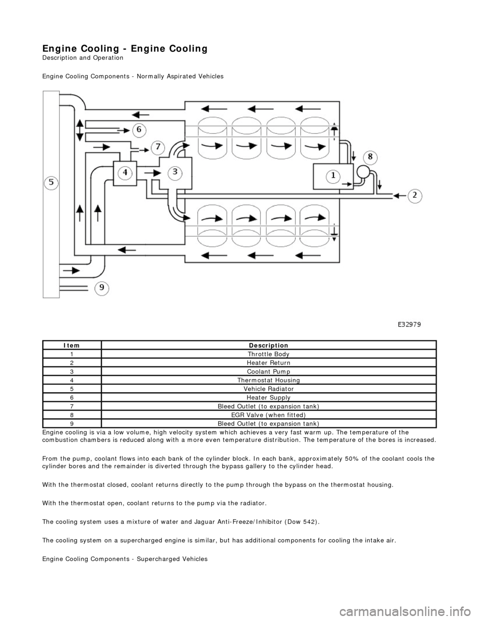
Engine Cooling Comp onents - Normally Aspirated Vehicles
Engine cooling is via a low volume, high velocity system which achieves a very fast warm up. The temperature of the
combustion chambers is reduced along with a more even temperature distribution. The temperature of the bores is increased.
F r
om the pump, coolant flows into each bank of the cylinder bl
ock. In each bank, approximately 50% of the coolant cools the
cylinder bores and the remainder is diverted th rough the bypass gallery to the cylinder head.
With the thermostat closed, coolant returns directly to the pump through the bypass on the thermostat housing.
With the thermostat open, coolant returns to the pump via the radiator.
The cooling system uses a mixture of water and Jaguar Anti-Freeze/Inhibitor (Dow 542).
The cooling system on a supercharged engine is similar, but has additional components for cooling the intake air.
Engine Cooling Co mponents - Supercharged Vehicles
ItemDescrip
tion
1Thr
ottle B
ody
2Hea
ter Return
3Coolant Pum p
4Ther
mostat Housing
5Vehicle Radia
t
or
6Hea
ter Su
pply
7Bleed
Outl
et (to expansion tank)
8EGR V
a
lve (when fitted)
9Bleed
Outl
et (to expansion tank)