message JAGUAR X308 1998 2.G Workshop Manual
[x] Cancel search | Manufacturer: JAGUAR, Model Year: 1998, Model line: X308, Model: JAGUAR X308 1998 2.GPages: 2490, PDF Size: 69.81 MB
Page 23 of 2490

В
В В В В В 413‐08:В Information В and В Message В Ce nter В
В В В В В В В В В В В В В В В В Descriptio
n
В and В Operation В
В В В В В В В В В В В В В В В В В В В В Information В and В Message В Center В
В В В В В В В В В В В В В В В В Diagnosis В and В Testing В
В В В В В В В В В В В В В В В В В В В В Information В and В Message В Center В
В В В В В В В В В В В В В В В В RemovalВ and В Installation В
В В В В В В В В В В В В В В В В В В В В MessageВ Center В Switch В (86.66.11) В
В
В В В В В В В В В В В В 413‐13: В ParkingВ AidВ
В В В В В В В В В В В В В В В В Description В and В Operation В
В В В В В В В В В В В В В В В В В В В В ParkingВ Aid В
В В В В В В В В В В В В В В В В Diagnosis В and В Testing В
В В В В В В В В В В В В В В В В В В В В ParkingВ Aid В
В В В В В В В В В В В В В В В В RemovalВ andВ Installation В
В В В В В В В В В В В В В В В В В В В В ParkingВ Aid В Module В (86.80.39) В
В В В В В В В В В В В В В В В В В В В В RearВ Parking В Aid В Sensor В (86.54.
14)В (86.62.01) В
В В В В В В В В В В В В В В В В В В В В RearВ Parking В Aid В Speaker В (86.54.19) В (86.62.02) В
В
В В В В В В В В 414: В Battery В and В Charging В System В
В
В В В В В В В В В В В В 414‐00: В Battery В and В ChargingВ System ‐ General В Information В
В В В В В В В В В В В В В В В В Description В and В Operation В
В В В В В В В В В В В В В В В В В В В В В В В В В В В В В В В В В В В В В В В В
В В В В В В В В В В В В В В В В В В В В В
В В В В В В В В В В В В 414
‐01:  Battery,  Mounting  and  Ca
bles В
В В В В В В В В В В В В В В В В Description
В and В Operation В
В В В В В В В В В В В В В В В В В В В В Battery
В and В Cables В
В В В В В В В В В В В В В В В В General
В Procedures В
В В В В В В В В В В В В В В В В В В В В Battery
В Connect В (86.15.15) В
В В В В В В В В В В В В В В В В Removal
В and В Installation В
В В В В В В В В В В В В В В В В В В В В Battery
В (86.15.01) В
В В В В В В В В В В В В В В В В В В В В Battery
В Ground В Cable В (86.15.19) В
В В В В В В В В В В В В В В В В В В В В Battery
В Positive В Cable В (86.15.17) В
В В В В В В В В В В В В В В В В В В В В Battery
В Retaining В Bracket В (86.15.12) В
Page 47 of 2490
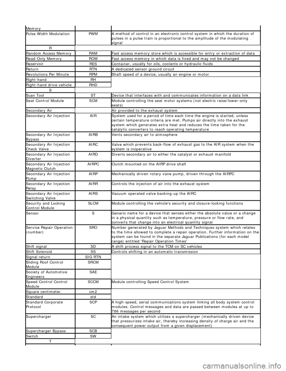
Mem
ory
Pulse Width ModulationPW
M
A
method of control in an electronic co
ntrol system in which the duration of
pulses in a pulse train is proportional to the amplitude of the modulating
signal
R
Ran
dom Access Memory
RAMF
ast access memory store which is accessible for entry or extraction of data
Re
ad-Only Memory
RO
M
F
ast access memory in which data
is fixed and may not be changed
Re
servoir
RESContaine
r, usually for oils,
coolants or hydraulic fluids
Re
turn
RTNA
dedicated sensor ground circuit
R
evolutions Per Minute
RP
M
Shaft speed o
f a device, us
ually an engine or motor
R
ight-hand
RH
Right-hand drive veh
icle
RHD
S
Scan T
ool
STDe
vice that interfaces with and comm
unicates information on a data link
Se
at Control Module
SCMModule
controlling the seat motor systems (not electric raise/lower-only
seats)
Secon
dary Air
Air pro
vided to the exhaust system
Secon
dary Air Injection
AIRSy
stem used for a period of time each
time the engine is started, unless
certain temperature criter ia are met. Pumps air directly into the exhaust
system which generates extra heat and reduces the time taken for the
catalytic converters to reach operating temperature
Secon
dary Air Injection
Bypass
AIRBVents secon
dary air to atmosphere
Secon
dary Air Injection
Check Valve
AIRCValve wh
ich prevents back-flow of exhaust gas to the AIR system when the
system is inoperative
Secon
dary Air Injection
Diverter
AIRDD
iverts secondary air to either
the catalyst or exhaust manifold
Secon
dary Air Injection
Magnetic Clutch
AIRP
C
Clu
tch mounted on the AIRP drive shaft
Secon
dary Air Injection
Pump
AIRPMe
chanically driven rotary vane
pump, driven through the AIRPC
Secon
dary Air Injection
Relay
AIRRCont
rols the injection of air into the exhaust system
Secon
dary Air Injection
Switchin
g Va
lve
AIRSV
acuum operated valve backing-up the AIRC
Secu
rity and Locking
Control Module
SLCMModul
e controlling the vehicle's security and closure-locking functions
SensorSGeneri
c name for a device
that senses either the absolute value or a change
in a physical quantity su ch as temperature, pressure or flow rate, and
converts that change into an electrical quantity signal
Servic
e Repair Operation
(number)
SRONu
mber generated by Jaguar Methods
and Techniques system which relates
to the time allowed to complete a repair operation. Further information on the
system can be found in the separate Jaguar Publications (for each model
range) entitled 'Repair Operation Times'
Shif
t signal
SDA
shift process signal to the TCM on SC vehicles
Shif
t Solenoid
SSControls shi
fting in an automatic transmission
Si
gnal return
SIG RTN
Slidin
g Roof Control
Module
SRCM
Society of Automotive
Engineers
SAE
Speed
Control Control
Module
SCCMModule con
trolling Speed Control System
Square c
entimeter
cm
2
Stan
dard
std
Stan
dard Corporate
Protocol
SCPA
high-speed, serial communications system linking all body system control
modules. Control messages and data ar e passed between modules at up to
786 messages per second
SuperchargerSCAn in
take system which utilizes a supercharger (mechanically driven device
that pressurizes intake air, thereby in creasing density of charge air and the
consequent power output from a given displacement)
Supercharger
Bypass
SCB
SwitchSW
T
Page 275 of 2490
пЃ¬R
equire no adjustment and are non-serviceable items.
Accelerometers
The three accelerometers:
пЃ¬Sense veh
icle body movement.
пЃ¬Gen
erate an analogue voltag
e (maximum +5 volts) proportional to body movement.
пЃ¬Pr
ovide inputs to the adapti
ve damping control module.
The two vertical acce lerometers are mounted on the bulkhead and in the trunk.
The lateral accelerometer is mounted in the ECM housing.
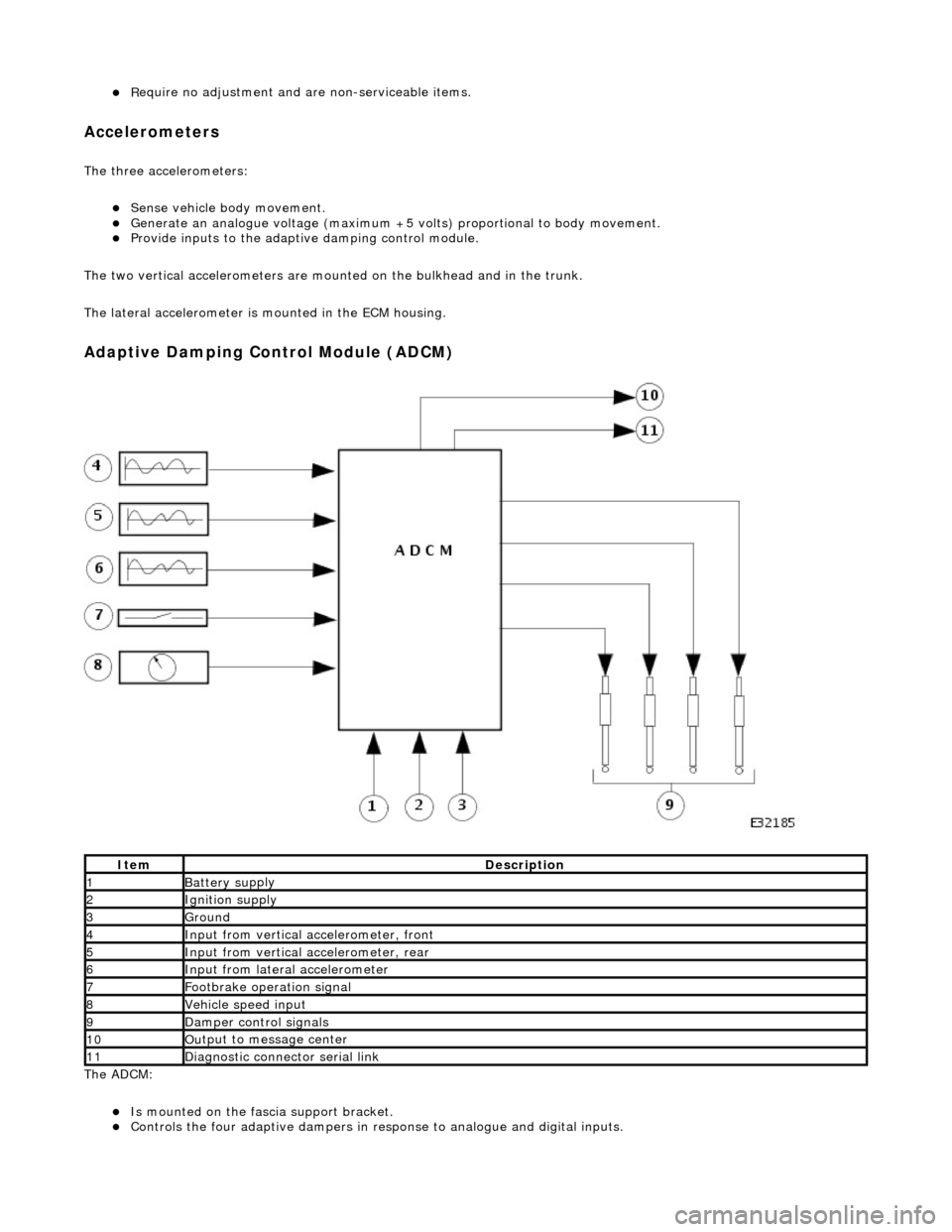
Ada
ptive Damping Control Module (ADCM)
The ADCM
:
пЃ¬Is
mounted on the fascia support bracket.
пЃ¬Controls the four adaptiv
e dampers in re
sponse to analogue and digital inputs.
It
em
De
scription
1Battery su
pply
2Ignition su
pply
3Ground
4Input from verti
cal accelerometer, front
5Input from verti
cal accelerometer, rear
6Input from later
al accelerometer
7F
ootbrake operation signal
8Vehi
cle speed input
9D
amper control signals
10Ou
tput to message center
11D
iagnostic connector serial link
Page 276 of 2490
пЃ¬Is hard-wi
red to the instrume
nt cluster message center.
пЃ¬Is hard
-wired to the J1962 diagnostic connector.
Op
era
tion
Th
e
system selects the soft or
firm damper setting according to the current ro ad and driving conditions, to optimise vehicle
ride and handling.
With the vehicle stationary, the dampers are in the firm setting, but will normally switch to the soft setting when the vehicle
exceeds 8 km/h (5 mile/h); all dampers are switched simultaneously.
Sudden movement of the vehicle body, in response to road inputs, is detected by the vertical accelerometers, and the ADCM
switches the dampers to the firm setting to give improved damping of the resultant oscillations.
When cornering forces are detected by th e lateral accelerometer, the ADCM switches the dampers to the firm setting to
reduce the roll rate an d improve wheel control.
After the event has passed, the dampers revert to the soft setting.
When the footbrake is applied, the ADCM re ceives a signal and calculates the rate of vehicle deceleration. If the deceleration
rate is greater than a certain threshold, the dampers are switched to the firm setting to reduce the pitch rate and improve
wheel control.
If a system failure occurs, the ADCM grounds the output line to the instrument cluster message center, which displays a
text warning SUSPENSION FAULT and illuminates the amber warning lamp. Under fault conditions the system always fails to
the firm setting, so that the vehicle will be safe to drive un der all road and driving conditions.
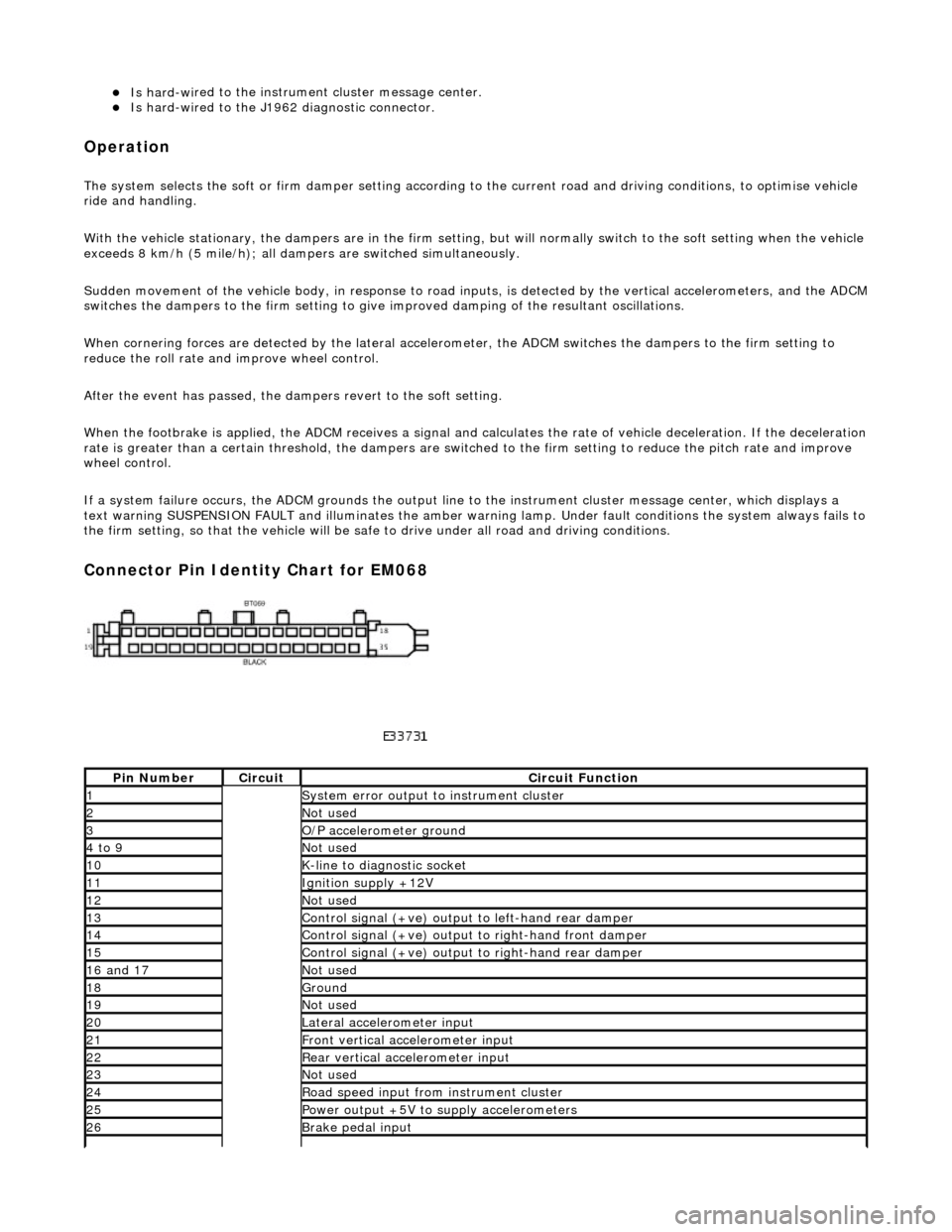
Connector Pin Identity Chart for EM068
Pin
Number
Ci
rcui
t
Circuit Functi
on
1System erro
r output to instrument
cluster
2Not
used
3O/
P a
ccelerometer ground
4 to
9
Not
used
10K-
li
ne to diagnostic socket
11Ignition su
pply +12V
12Not
used
13Control signal (+ve) output
to l
eft-hand rear damper
14Control signal (+ve) output
to right-hand front damp
er
15Control signal (+ve) output
to right-hand rear
damper
16
a
nd 17
No
t
used
18Ground
19No
t
used
20Lateral
accelerometer i
nput
21Front vertical ac
celerometer in
put
22Rear vertical
acce
lerometer input
23No
t
used
24R
o
ad speed input from
instrument cluster
25Power output +5V to suppl y accelerometers
26Brake peda
l input
Page 392 of 2490

means of a manual adjustment
mechanism
at each set of shoes. Refer to General Procedur es in section 206-05.
If the vehicle is driven above 5 km/h with the parking brake applied, a warning lamp and text message will appear on the
message center. The message clears when the brake is released or the speed drops below 3 km/h.
Parking Brake Shoe Arrangement
пЃ¬The adjuster mech
anism enables manual
adjustment of the brake shoes.
пЃ¬Retai
ning pins keep the shoes in contact with the dust shield.
пЃ¬The brake
shoes locate into the expander lever and the adjuster mechanism.
пЃ¬R
e
turn springs retr
act the brake shoes when the parking brake is released.
пЃ¬Th
e expander lever mechanism moves the brake shoes outwar
ds, in contact with the brake drum when the parking
brake is applied.
It e
m
Par
t
Number
De
scr
iption
1—Adjust
er Me
chanism
2—R
e
taining Pins
3—Brake Sh
oe
s
4—Upper
Return
Spring
5—Lower Return Spring
6—Expander
Lever Mechanism
Page 517 of 2490
o
perating. If an indicator bulb fails, the warning
lamp and ticking operate at twice the normal rate.
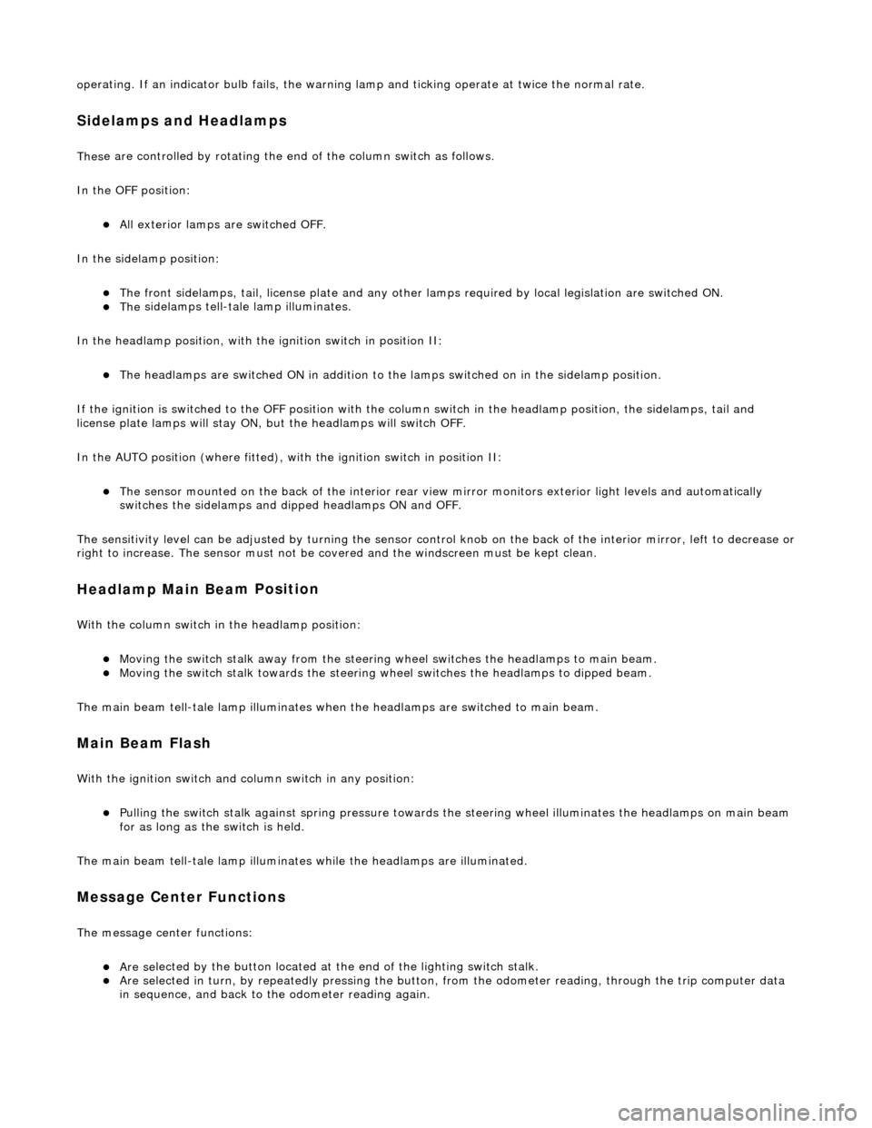
Sidelam
ps and Headlamps
Thes
e are controlled by rotating the end of the column switch as follows.
In the OFF position:
пЃ¬All
exterior lamps are switched OFF.
In the sidelamp position:
пЃ¬The front
sidelamps, tail, license plate and any other la
mps required by local legislation are switched ON.
пЃ¬The
sidelamps tell-tale lamp illuminates.
In the headlamp position, with the ignition switch in position II:
пЃ¬The h
eadlamps are switched ON in addition to the lamps switched on in the sidelamp position.
If the ignition is switched to the OFF position with the column switch in the headlamp position, the sidelamps, tail and
license plate lamps will stay ON, but the headlamps will switch OFF.
In the AUTO position (where fitted), with the ignition switch in position II:
пЃ¬Th
e sensor mounted on the back of the interior rear view
mirror monitors exterior light levels and automatically
switches the sidelamps and di pped headlamps ON and OFF.
The sensitivity level can be adjusted by turn ing the sensor control knob on the back of the interior mirror, left to decrease or
right to increase. The sensor must not be covered and the windscreen must be kept clean.
Headlamp Main Bea
m Position
Wi
th the column switch in
the headlamp position:
пЃ¬Movin
g the switch stalk away fro
m the steering wheel switches the headlamps to main beam.
пЃ¬Movin
g the switch stalk towards the steering wheel switches the headlamps to dipped beam.
The main beam tell-tale lamp illuminates when the headlamps are switched to main beam.
Ma
in Beam Flash
Wi
th the ignition switch and column switch in any position:
пЃ¬Pulling the
switch stalk agains
t spring pressure towards th e steering wheel illuminates the headlamps on main beam
for as long as the switch is held.
The main beam tell-tale lamp illuminates while the headlamps are illuminated.
M
essage Center Functions
T
he message center functions:
пЃ¬Are se
lected by the button located at the end of the lighting switch stalk.
пЃ¬Are se
lected in turn, by repeatedly pressing the button,
from the odometer reading, through the trip computer data
in sequence, and back to th e odometer reading again.
Page 518 of 2490
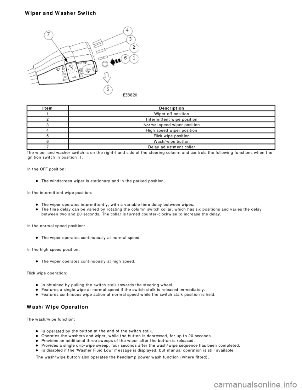
The wiper and washer switch i s
on the righ
t-hand side of the steering column and controls the fo llowing functions when the
ignition switch in position II.
In the OFF position:
пЃ¬The windscreen wiper is stationary and in the parked positio
n.
In the intermittent wipe position:
пЃ¬The wi per ope
rates intermittently, with
a variable time delay between wipes.
пЃ¬The time del
ay can be varied by rotating the column sw
itch collar, which has six positions and varies the delay
between two and 20 seconds. The collar is turned counter-clockwise to increase the delay.
In the normal speed position:
пЃ¬The wiper oper a
tes continuously at normal speed.
In the high speed position:
пЃ¬The wiper ope r
ates continuously at high speed.
Flick wipe operation:
пЃ¬Is obt
ained by pulling the switch
stalk towards the steering wheel.
пЃ¬F
e
atures a single wipe at normal speed if
the switch stalk is released immediately.
пЃ¬Fe
atures continuous wipe action
at normal speed while the swit ch stalk position is held.
Wash/W
ipe Operation
Th
e
wash/wipe function:
пЃ¬Is operat
ed by th
e button at the end of the switch stalk.
пЃ¬Op
erate
s the washers and wiper, while the butt
on is depressed, for up to 20 seconds.
пЃ¬Provides an addit
ional three sweeps of
the wiper after the button is released.
пЃ¬Provid
es a single drip-wipe sweep, four seconds af
ter the wash/wipe sequence has been completed.
пЃ¬Is disabled if the 'Washer Flu
id Low' message is di
splayed, but manual operat ion is still available.
Ite
m
De
scr
iption
1W
i
per off position
2Intermittent
wipe position
3Normal
speed wiper position
4High
speed wiper position
5Flick wipe position
6Wa
sh/wipe button
7D
e
lay adjustment collar
The was
h
/wipe button also operates the head
lamp power wash function (where fitted).
Wiper and Washer Switch
Page 1020 of 2490
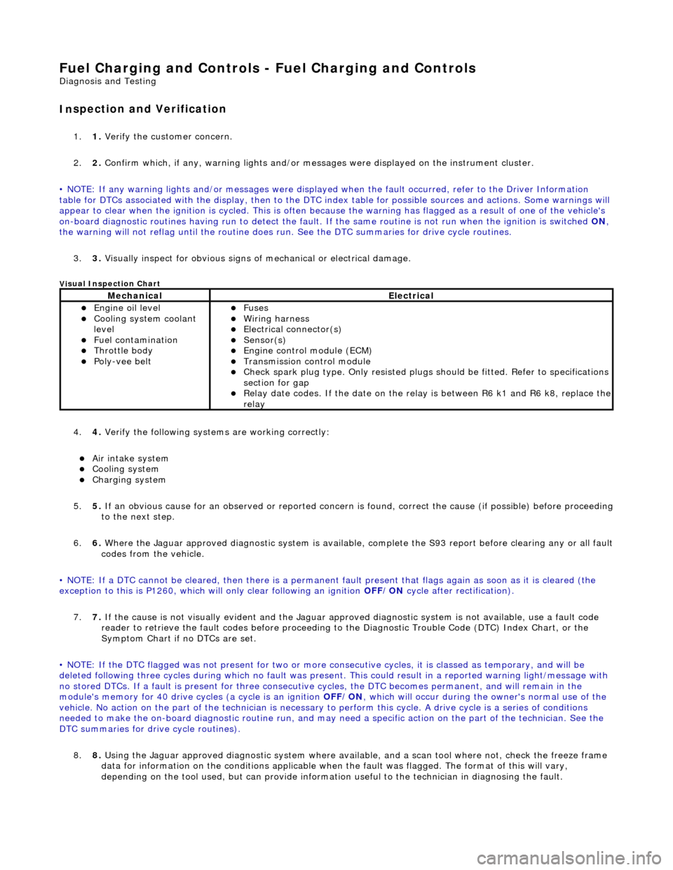
Fuel Char
ging and Controls - Fuel Charging and Controls
D
iagn
osis and Testing
I
n
spection and Verification
1.
1. Veri fy the customer concern.
2. 2. Confi
rm which, if any, warning li
ghts and/or messages were displayed on the instrument cluster.
• NOTE: If any warning lights and/or me ssages were displayed when the fault occurred, refer to the Driver Information
table for DTCs associated with the display, then to the DTC index table for possible sources and actions. Some warnings will
appear to clear when the ignition is cycl ed. This is often because the warning has flagged as a resu lt of one of the vehicle's
on-board diagnostic routines having run to detect the fault. If the same routine is not run when the ignition is switched ON,
the warning will not reflag until the routine does run. See the DTC summaries for drive cycle routines.
3. 3. Visually inspect for obvious signs of mechanical or electrical damage.
Vi
sual Inspection Chart
4.
4. Veri fy the foll
owing syst
ems are working correctly:
пЃ¬Air intake
system
пЃ¬Cooling system
пЃ¬Charging system
5. 5. If
an obvious cause for an observed or
reported concern is found, correct th e cause (if possible) before proceeding
to the next step.
6. 6. Where the Jaguar approved diagnostic sy stem is available, complete the S93 report before clearing any or all fault
codes from the vehicle.
• NOTE: If a DTC cannot be cleared, then there is a permanent fault present that flag s again as soon as it is cleared (the
exception to this is P1260, which will only clear following an ignition OFF/ON cycle after rectification).
7. 7. If the cause is not visually evident and the Jaguar approv ed diagnostic system is not available, use a fault code
reader to retrieve the fault codes be fore proceeding to the Diagnostic Trou ble Code (DTC) Index Chart, or the
Symptom Chart if no DTCs are set.
• NOTE: If the DTC flagged was not present for two or more co nsecutive cycles, it is classed as temporary, and will be
deleted following three cycl es during which no fault was present. This could result in a reported wa rning light/message with
no stored DTCs. If a fault is present for three consecutive cycles, the DTC becomes permanent, and will remain in the
module's memory for 40 drive cycl es (a cycle is an ignition OFF/ON, which will occur during the owner's normal use of the
vehicle. No action on the part of the technician is necessary to perform this cycle. A drive cycle is a series of conditions
needed to make the on-board diagnostic ro utine run, and may need a specific action on the part of the technician. See the
DTC summaries for drive cycle routines).
8. 8. Using the Jaguar approved diagnostic system where available, and a scan tool where not, check the freeze frame
data for information on the conditions applicable when the fault was flagged. The format of this will vary,
depending on the tool used, but can pr ovide information useful to the technician in diagnosing the fault.
MechanicalElectrical
пЃ¬Engine
oil level
пЃ¬Coo
ling system coolant
lev
el
пЃ¬Fuel contamination
пЃ¬Throttle body пЃ¬Poly-ve
e belt
пЃ¬Fu
ses
пЃ¬W
i
ring harness
пЃ¬E
l
ectrical connector(s)
пЃ¬Sens
o
r(s)
пЃ¬Engine
control module (E
CM)
пЃ¬Tran
s
mission control module
пЃ¬Check spark plu
g type. Only r
e
sisted plugs should be fitted. Refer to specifications
section for gap
пЃ¬Relay date codes. I
f the date on the rela
y is between R6 k1 and R6 k8, replace the
relay
Page 1077 of 2490
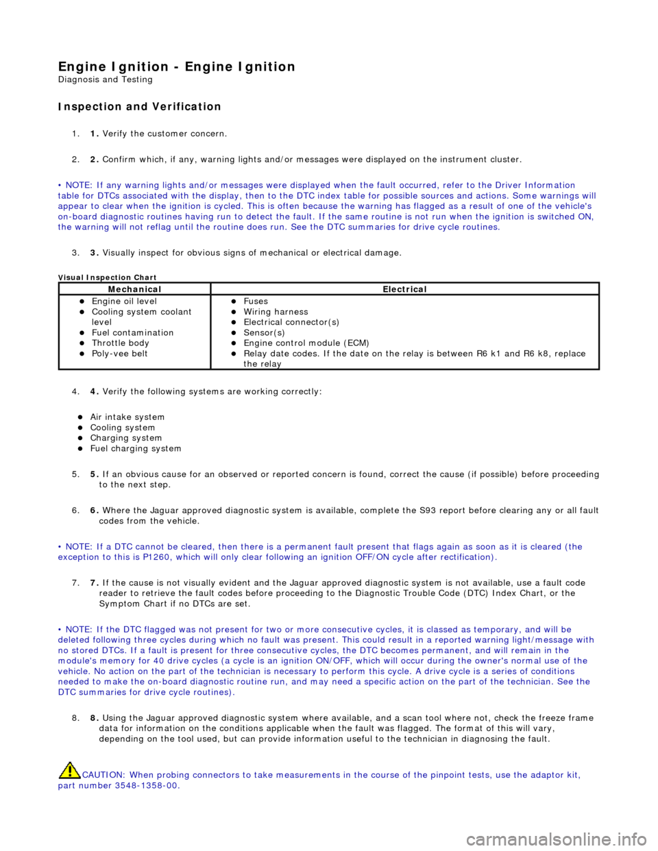
Engine Igni
tion -
Engine Ignition
D
iagnosis and Testing
I
nspection and Verification
1.
1. Veri
fy the customer concern.
2. 2. Confirm which, if any, warning li ghts and/or messages were displayed on the instrument cluster.
• NOTE: If any warning lights and/or me ssages were displayed when the fault occurred, refer to the Driver Information
table for DTCs associated with the display, then to the DTC index table for possible sources and actions. Some warnings will
appear to clear when the ignition is cycl ed. This is often because the warning has flagged as a resu lt of one of the vehicle's
on-board diagnostic routines having run to detect the fault. If the same routine is not run when the ignition is switched ON,
the warning will not reflag until the routine does run. See the DTC summaries for drive cycle routines.
3. 3. Visually inspect for obvious signs of mechanical or electrical damage.
V
isual Inspection Chart
4.
4. Veri
fy the following syst
ems are working correctly:
пЃ¬Air in
take system
пЃ¬Coo
ling system
пЃ¬Charging system
пЃ¬F
uel charging system
5. 5. If an obvious cause for an observed or reported concern is found, correct the cause (if possible) before proceeding
to the next step.
6. 6. Where the Jaguar approved diagnostic sy stem is available, complete the S93 report before clearing any or all fault
codes from the vehicle.
• NOTE: If a DTC cannot be cleared, then there is a permanent fault present that flag s again as soon as it is cleared (the
exception to this is P1260, which will only clear following an ignition OFF/ON cycle after rectification).
7. 7. If the cause is not visually evident and the Jaguar approv ed diagnostic system is not available, use a fault code
reader to retrieve the fault codes be fore proceeding to the Diagnostic Trou ble Code (DTC) Index Chart, or the
Symptom Chart if no DTCs are set.
• NOTE: If the DTC flagged was not present for two or more co nsecutive cycles, it is classed as temporary, and will be
deleted following three cycl es during which no fault was present. This could result in a reported wa rning light/message with
no stored DTCs. If a fault is present for three consecutive cycles, the DTC becomes permanent, and will remain in the
module's memory for 40 drive cycles (a cy cle is an ignition ON/OFF, which will occur during the owner's normal use of the
vehicle. No action on the part of the technician is necessary to perform this cycle. A drive cycle is a series of conditions
needed to make the on-board diagnostic ro utine run, and may need a specific action on the part of the technician. See the
DTC summaries for driv e cycle routines).
8. 8. Using the Jaguar approved diagnostic system where available, and a scan tool where not, check the freeze frame
data for information on the conditions applicable when the fault was flagged. The format of this will vary,
depending on the tool used, but can pr ovide information useful to the technician in diagnosing the fault.
CAUTION: When probing connectors to take measurements in the course of the pinpoint tests, use the adaptor kit,
part number 3548-1358-00.
MechanicalElectrical
пЃ¬Engi
ne oil level
пЃ¬Coo
ling system coolant
level
пЃ¬Fuel contamination
пЃ¬Throttle body пЃ¬Poly
-vee belt
пЃ¬F
uses
пЃ¬W
iring harness
пЃ¬E
lectrical connector(s)
пЃ¬Sens
or(s)
пЃ¬Engine
control module (ECM)
пЃ¬Relay date codes.
If the date on the relay is between R6 k1 and R6 k8, replace
the relay
Page 1189 of 2490
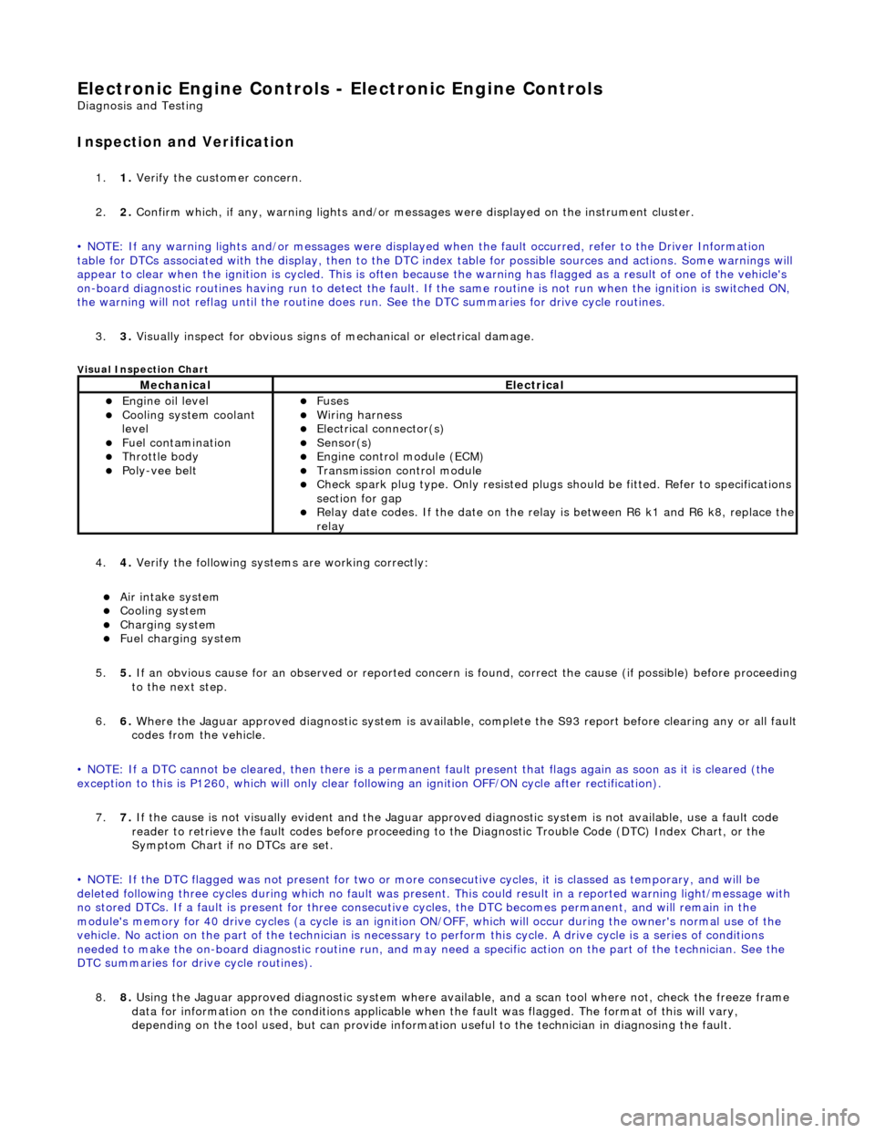
E
lectronic Engine Controls -
Electronic Engine Controls
D
iagnosis and Testing
I
nspection and Verification
1.
1. Veri
fy the customer concern.
2. 2. Confirm which, if any, warning li ghts and/or messages were displayed on the instrument cluster.
• NOTE: If any warning lights and/or me ssages were displayed when the fault occurred, refer to the Driver Information
table for DTCs associated with the display, then to the DTC index table for possible sources and actions. Some warnings will
appear to clear when the ignition is cycl ed. This is often because the warning has flagged as a resu lt of one of the vehicle's
on-board diagnostic routines having run to detect the fault. If the same routine is not run when the ignition is switched ON,
the warning will not reflag until the routine does run. See the DTC summaries for drive cycle routines.
3. 3. Visually inspect for obvious signs of mechanical or electrical damage.
V
isual Inspection Chart
4.
4. Veri
fy the following syst
ems are working correctly:
пЃ¬Air in
take system
пЃ¬Coo
ling system
пЃ¬Charging system
пЃ¬F
uel charging system
5. 5. If an obvious cause for an observed or reported concern is found, correct the cause (if possible) before proceeding
to the next step.
6. 6. Where the Jaguar approved diagnostic sy stem is available, complete the S93 report before clearing any or all fault
codes from the vehicle.
• NOTE: If a DTC cannot be cleared, then there is a permanent fault present that flag s again as soon as it is cleared (the
exception to this is P1260, which will only clear following an ignition OFF/ON cycle after rectification).
7. 7. If the cause is not visually evident and the Jaguar approv ed diagnostic system is not available, use a fault code
reader to retrieve the fault codes be fore proceeding to the Diagnostic Trou ble Code (DTC) Index Chart, or the
Symptom Chart if no DTCs are set.
• NOTE: If the DTC flagged was not present for two or more co nsecutive cycles, it is classed as temporary, and will be
deleted following three cycl es during which no fault was present. This could result in a reported wa rning light/message with
no stored DTCs. If a fault is present for three consecutive cycles, the DTC becomes permanent, and will remain in the
module's memory for 40 drive cycles (a cy cle is an ignition ON/OFF, which will occur during the owner's normal use of the
vehicle. No action on the part of the technician is necessary to perform this cycle. A drive cycle is a series of conditions
needed to make the on-board diagnostic ro utine run, and may need a specific action on the part of the technician. See the
DTC summaries for driv e cycle routines).
8. 8. Using the Jaguar approved diagnostic system where available, and a scan tool where not, check the freeze frame
data for information on the conditions applicable when the fault was flagged. The format of this will vary,
dependin
g o
n the tool used, but can provide information useful to the technician in dia
gnos
in
g th
e fault.
MechanicalElectrical
пЃ¬Engi
ne oil level
пЃ¬Coo
ling system coolant
level
пЃ¬Fuel contamination
пЃ¬Throttle body пЃ¬Poly
-vee belt
пЃ¬F
uses
пЃ¬W
iring harness
пЃ¬E
lectrical connector(s)
пЃ¬Sens
or(s)
пЃ¬Engine
control module (ECM)
пЃ¬Tran
smission control module
пЃ¬Check spark plu
g type. Only re
sisted plugs should be fitted. Refer to specifications
section for gap
пЃ¬Relay date codes.
If the date on the rela
y is between R6 k1 and R6 k8, replace the
relay