message JAGUAR X308 1998 2.G Owner's Manual
[x] Cancel search | Manufacturer: JAGUAR, Model Year: 1998, Model line: X308, Model: JAGUAR X308 1998 2.GPages: 2490, PDF Size: 69.81 MB
Page 1904 of 2490
Audio Unit - Audio System
Description and Operation
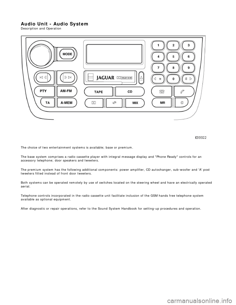
The choice of two entertainment system s is available; base or premium.
The base system comprises a radio cassette player with in tegral message display and "Phone Ready" controls for an
accessory telephone; door speakers and tweeters.
The premium system has the following additional components: power amplifier, CD autochanger, sub-woofer and 'A' post
tweeters fitted instead of front door tweeters.
Both systems can be operated remotely by use of switches loca ted on the steering wheel and have an electrically operated
aerial.
Telephone controls incorporated in the ra dio cassette unit facilitate inclusion of the GSM hands free telephone system
available as optional equipment.
After diagnostic or repair operations, refer to the Sound System Handbook for setting-up procedures and operation.
Page 1905 of 2490
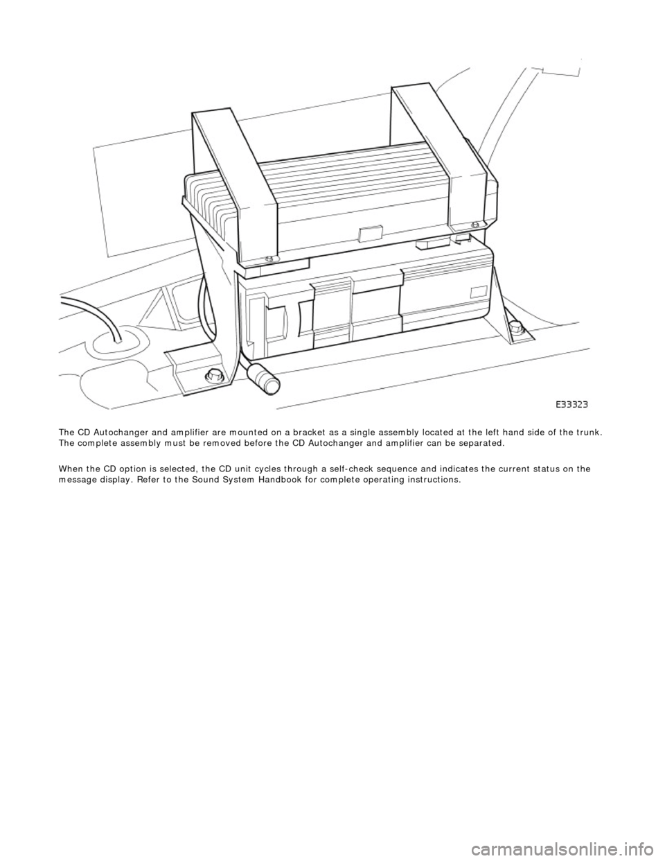
The CD Autochanger and amplifier are mounte d on a bracket as a single assembly located at the left hand side of the trunk.
The complete assembly must be removed before the CD Autochanger and amplifier can be separated.
When the CD option is selected, the CD unit cycles through a self-check sequence and indicates the current status on the
message display. Refer to the Sound System Ha ndbook for complete operating instructions.
Page 1964 of 2490
Interior Lighting - Interior Lighting
Diagnosis and Testing
Tests Using the Portable Diagnostic Unit
Refer to PDU User Guide
The complexity of the electronics involved with the various Electronic Control Modules and the multiplexed communication
networks, preclude the use of workshop general electrical test equipment. Therefore, reference should be made to the PDU
User Guide for detailed inst ructions on testing the interior lamps and circuits.
The PDU systematically tests and analyses the lamp assemblies, the bulbs and the electrical connections to them. It should
be noted that the lamps are not wired directly to the switches.
The lamps are controlled directly by the Bo dy Processor (it has a sufficient number of high power output stages to drive the
lamps / relays compared to other module s) except for the door guard / puddle lamps and the rear passenger reading lamps.
The Body Processor Module receives messages on the SCP network from the door modules relating to door ajar / closed /
locked status, sensed by the door courtesy switch(es).
Where a fault involving a lamp is indicated by the PDU, be fore replacing suspect components, some basic diagnostic
methods may be necessary to confirm that connecti ons are good and that wiring is not damaged.
Page 2307 of 2490
cooling duct.
The windshield washer is operated by pressing the button at the end of the wiper control stalk switch. Pressing and
releasing the button operates the washer for 1 to 1.4 seconds and the wiper completes three sweeps. An optional drip wipe
function adds a further sweep of the wiper after a 4 second delay, to clear residual fluid from the windshield. If the button is
held depressed, the washer and wiper will operate continuous ly for up to 20 seconds. When the button is released, the
wiper will again complete three further sweeps.
Headlamp Powerwash
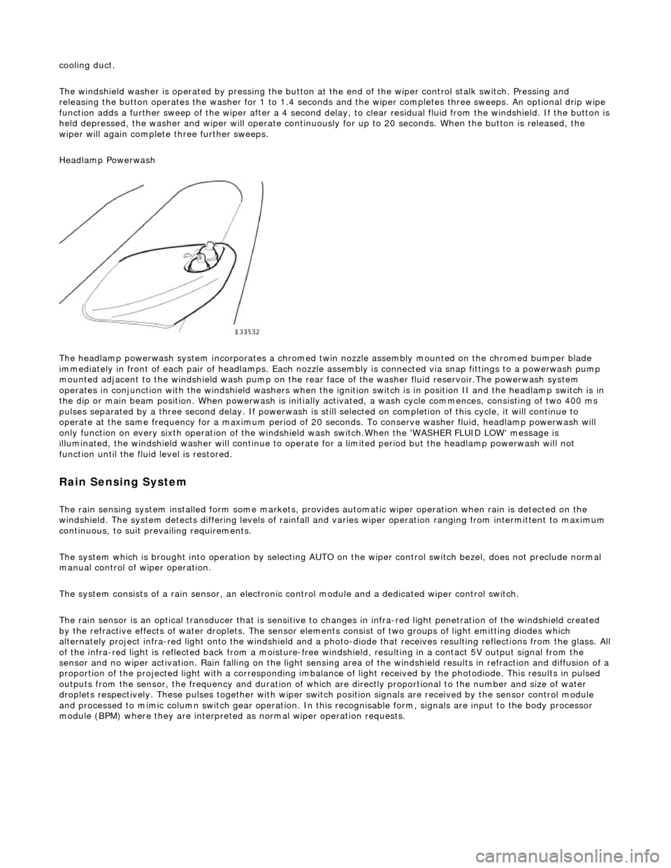
The headlamp powerwash system incorporates a chromed twin nozzle assembly mounted on the chromed bumper blade
immediately in front of each pair of he adlamps. Each nozzle assembly is connected via snap fittings to a powerwash pump
mounted adjacent to the windshield wash pump on the rear face of the washer fluid reservoir.The powerwash system
operates in conjunction with the windshield washers when the ignition switch is in position II and the headlamp switch is in
the dip or main beam position. When powerwash is initially activated, a wash cycle commences, consisting of two 400 ms
pulses separated by a three second delay. If powerwash is still selected on completion of this cycle, it will continue to
operate at the same frequency for a maximum period of 20 se conds. To conserve washer fluid, headlamp powerwash will
only function on every sixth operation of the windshie ld wash switch.When the 'WASHER FLUID LOW' message is
illuminated, the windshield washer will continue to operat e for a limited period but the headlamp powerwash will not
function until the fluid level is restored.
Rain Sensing System
The rain sensing system installed form so me markets, provides automatic wiper operation when rain is detected on the
windshield. The system detects differing le vels of rainfall and varies wiper operation ranging from intermittent to maximum
continuous, to suit prevailing requirements.
The system which is brought into operation by selecting AUTO on the wiper control switch bezel, does not preclude normal
manual control of wiper operation.
The system consists of a rain sensor, an electronic control module and a dedicated wiper control switch.
The rain sensor is an optical transducer that is sensitive to changes in infra-red light penetration of the windshield created
by the refractive effects of water drople ts. The sensor elements consist of two groups of light emitting diodes which
alternately project infra-red light onto th e windshield and a photo-diode that receiv es resulting reflections from the glass. A ll
of the infra-red light is reflected back from a moisture-free windshield, resulting in a contact 5V output signal from the
sensor and no wiper activation. Rain falling on the light sensing area of the wi ndshield results in refraction and diffusion of a
proportion of the projected light with a corresponding imbalance of light received by the photodiode. This results in pulsed
outputs from the sensor, the frequency and duration of which are directly proportional to the number and size of water
droplets respectively. These pulses together with wiper switch position signals are received by the sensor control module
and processed to mimic column switch gear operation. In this recognisable form, signals are input to the body processor
module (BPM) where they are interprete d as normal wiper operation requests.
Page 2382 of 2490
Health and Safety
It is the duty of both employer and employee to ensure safe working conditions and practices. Correct safety procedures
and equipment must be applied to any potential hazards that are notified, or identified by an operator.
Employees must observe local legislation go verning working conditions and practices at all times and must always act in a
responsible manner in the workplace. In the event of personal injury resulting from any workshop activity, medical help
should be obtained as soon as poss ible. Self-treatment other than by first aid, should not be attempted.
WARNING: READ AND UNDERSTAND WORKING PRACTICE S CONCERNING CLIMATE CONTROL SYSTEMS, SECTION
412, WITH SPECIAL REGARD TO: REFRIGERANT MUST NEVE R BE DIRECTLY VENTED TO ATMOSPHERE. ALWAYS USE
JAGUAR APPROVED RECOVERY / RECYCLE / RECHARGE EQUI PMENT, WEAR SUITABLE EYE AND SKIN PROTECTION AND
OBSERVE ALL APPLICABLE SAFETY REQUIREMENTS.
With the constant introduction of new materials in the manufacture of vehicles, an awareness of the potential risks and
appropriate precauti ons is important.
Notification of Hazards
Symbols, which convey important information, will be positioned at the beginning of any specific operation or text. Standard symbols will be used where repairs or service procedures ar e detailed. All symbols will conform to standard ANSI Z535.3
(American National Standards Institute). The surround shape of the symbol will indicate the basis of the message to be
conveyed (see top three elements of ?) The icon depicting the message will be within the surrounding shape. Once
nominated the icon will retain its meaning.
POTENTIAL RISKS
Paint
Organic solvents, found in paints, may caus e damage or severe irritation to liver, kidneys, digestive tracts and respiratory
system if inhaled over long pe riods of time. Prolonged exposure to isocyanate s can cause lung sensitization with asthma-like symptoms developing on subsequent exposure to even low concentrations of isocyanates. Solvent inhalation can cause
dizziness or loss of consciousness and inhalation of spray dust and sanding debris may cause lung damage.
Spillage or splashes of solvents, paint ac tivators and additives can cause dermatitis or eye injury. Contact with peroxide or
acid catalysts can cause serious burns.
Applied Heat (Welding)
There is considerable risk of damage to eyes and skin if welding or flame cutting is attempted without using the correct
protective equipment. Many materials or fluids within vehicles are highly flammable and toxic and dangerous fumes may
also be liberated if heat is applied to expanded foam, corr osion protection, trim and seat materials, paints containing
isocyanates, and adhesive and sealing compounds.
When heated to a temperature of 300В°C, polyurethane based compounds may liberate small quantities of isocyanate. Many
types of nitrogen containing chemicals ma y be liberated as breakdown products which can contain isocyanates, oxides of
nitrogen and hydrogen cyanide.
Potentially toxic or asphyxiant fumes and gases produced when welding include zinc oxide from zinc coated panels, and
ozone gas from the MIG process.
Metal Repair
There is considerable risk of damage to eyes, ears and skin wh en cutting, forming, or dressing metal. Soldering operations
can also be hazardous due to heat generated fumes and the risk of skin contact with hot materials.
PRECAUTIONS