replace battery JAGUAR X308 1998 2.G Workshop Manual
[x] Cancel search | Manufacturer: JAGUAR, Model Year: 1998, Model line: X308, Model: JAGUAR X308 1998 2.GPages: 2490, PDF Size: 69.81 MB
Page 38 of 2490
Torque Specifications
Torque sp
ecifications are shown in maintenance procedure illustra
tions and also in the torque specifications chart located at
the front of the relevant section.
Disconnecting/Connecting the Battery
Ow ing t
o the electronic components used on the vehicle, it is important that the battery is disconnected when specified in a
maintenance procedure.
When the battery is connected, the specified procedure must be followed, to ensure the correct operation of all vehicle
systems; refer to Section 414-01.
Use of Control Modules
Control modu les may
only be used on the ve
hicle to which they were originally fitted. Do not attempt to use or test a control
module on any other vehicle.
Function
al Test
On
completion of a maintenance procedure, a thorough test should be carried out, to ensu
re that the relevant vehicle
systems are working correctly.
Protecting the Vehicle
Al ways
fit covers to protect
the fenders before commencing work in the engi ne compartment. Cover the seats and carpets,
wear clean overalls and wash hands or wear gloves before working inside the vehicle. Avoid spilling hydraulic fluid,
antifreeze or battery acid on the paintwork. In the event of spillage, wash off with water imme diately. Use polythene sheets
in the trunk to protect carpets. Always use the recommended service tool, or a satisfactory equivalent, where specified.
Protect temporarily exposed screw thread s by replacing nuts or fitting caps.
Preparation
Before disassembly, clean the surrounding ar ea
as thoroughly as possible. When co
mponents have been removed, blank off
any exposed openings using grease-proof paper and masking tape. Immediately seal fuel, oil and hydraulic lines when
separated, using plastic caps or plugs, to prevent loss of fluid and the entry of dirt. Close the open ends of oilways, exposed
by component removal, with tapered hardw ood plugs or readily visible plastic plugs. Immediately a component is removed,
place it in a suitable container; use a se parate container for each component and its associated pa rts. Before dismantling a
component, clean it thoroughly with a recommended cleaning agent; check that the agent will not damage any of the
materials within the component. Clean the bench and obtain ma rking materials, labels, containers and locking wire before
dismantling a component.
Dismantling
O b
serve scrupulous cleanliness when dismantling components,
particularly when parts of the brake, fuel or hydraulic
systems are being worked on. A particle of dirt or a fragment of cloth could caus e a dangerous malfunction if trapped in
these systems. Clean all tapped holes, crev ices, oilways and fluid passages with compressed air. Do not permit compressed
air to enter an open wound. Always use ey e protection when using compressed air.
Ensure that any O-rings used for sealing are correctly refitted or renewed if disturbed. Mark mating parts to ensure that
they are replaced as dismantled. Whenever possible use markin g materials which avoid the possibilities of causing distortion
or the initiation of cracks, which could occur if a center pu nch or scriber were used. Wire together mating parts where
necessary to prevent accidental interchange (e.g roller bearing components). Tie labels on to all parts to be renewed and to
parts requiring further inspection before being passed fo r reassembly. Place labelled parts and other parts for rebuild in
separate containers. Do not disc ard a part which is due for renewal until it ha s been compared with the new part, to ensure
that the correct part has been obtained.
Page 291 of 2490
R
ear Drive Axle/Differential - Differential Output Shaft Bearing
In-v
ehicle Repair
Remov
al
S
pecial Tool(s)
Replacer hu
b bearing
204-083
1. Di
sconnect the battery ground lead
2. Raise the vehicle for access
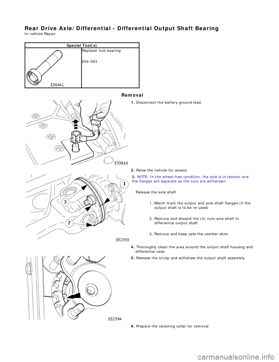
3. NO
TE: In the wheel-free condition, the axle is in tension and
the flanges will separate as the nuts are withdrawn
Release the axle shaft
1. Match mark the output an d axle shaft flanges (if the
output shaft is to be re-used)
2. Remove and discard the (4) nuts axle shaft to differential output shaft
3. Remove and keep safe the camber shim
4. T
horoughly clean the area around the output shaft housing and
differential case
5. Relea
se the circlip and withdraw the output shaft assembly
6. Prepare the retaining collar for removal
Page 295 of 2490
R
ear Drive Axle/Differential - Drive Pinion Flange and Drive Pinion Seal
In-v
ehicle Repair
Remov
al
S
pecial Tool(s)
Drive sh
aft flange wrench
205-053
D
rive shaft flange remover replacer.
205-272
1. Di
sconnect the battery ground lead.
2. Raise the vehicle for access.
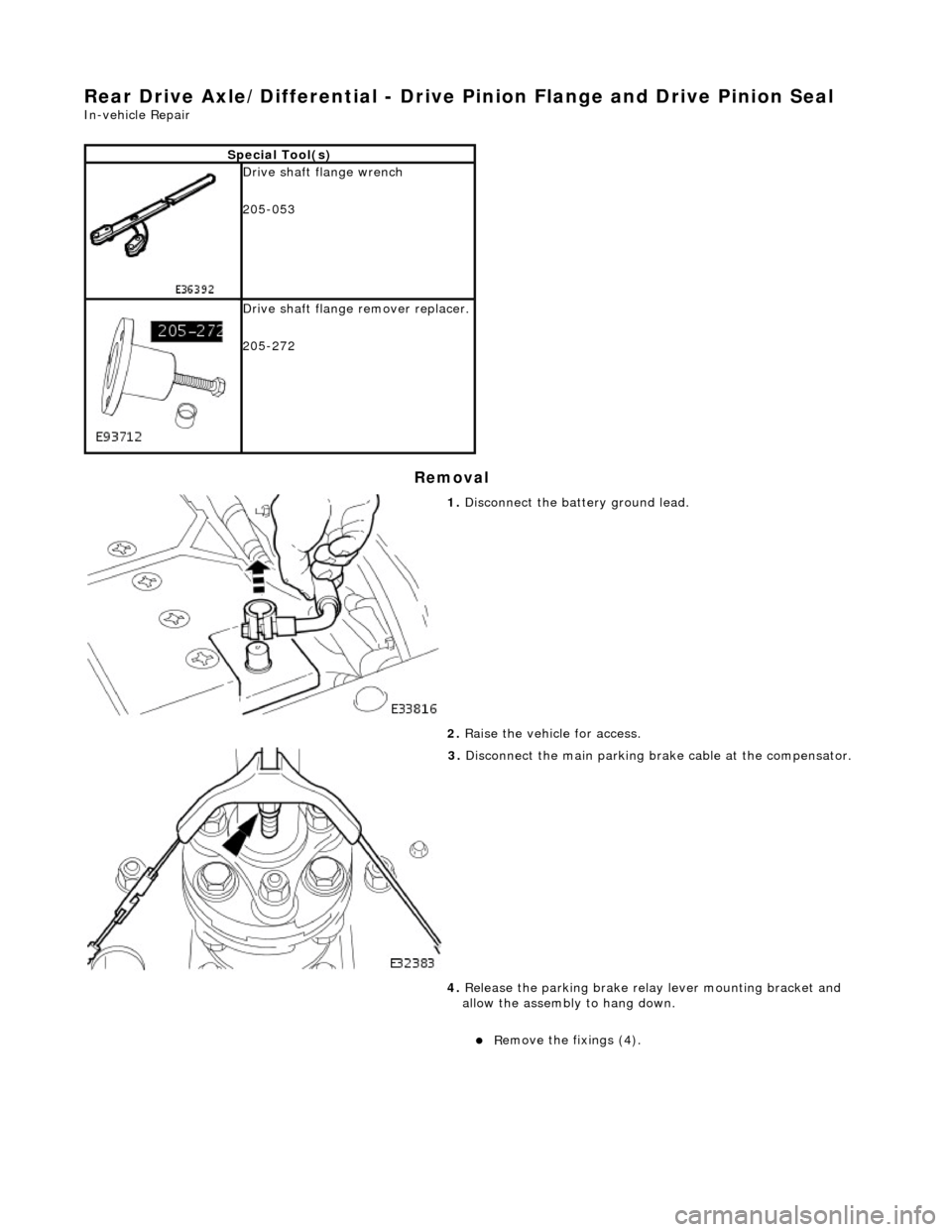
3. Disconnect the main parking br ake c
able at the compensator.
4. Release the parking brake relay lever mounting bracket and
allow the assembly to hang down.
R
emove the fixings (4).
Page 408 of 2490
Hydraulic Br
ake Actuation
- Brake Fluid Reservoir
Remo
val and Installation
Remov
a
l
• C
A
UTIONS:
Replacement of nuts and bolts: Various thread-locking de vices are used on nuts and bolts throughout the vehicle.
These devices restrict the number of times a nut or bolt can be used. See section 100-00 for information.
Remove brake fluid spilla ge immediately from paint work, with clean water.
1. Position vehicl
e on a four-post lift.
2. Open engine compartment and fit paint work protection covers
to fenders.
3. Disconnect battery ground cable (IMPORTANT, see operation
86.15.19 for further information).
4. Remove engine compartment rear cover. Refer to operation
76.11.35.
5. Remove pedal housing, brake booster and master cylinder
assembly. Refer to operation 70.35.39.
6. Remove reservoir filler cap and empty residual brake fluid into
a container. Refit cap.
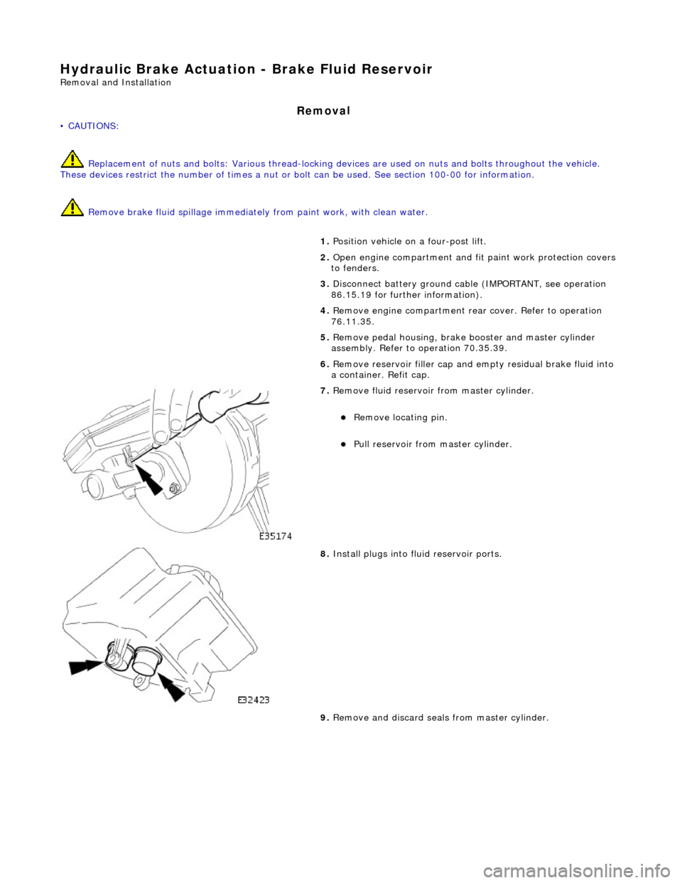
7. Re
move fluid reservoir from master cylinder.
R
e
move locating pin.
Pull reservoir
from master cylinder.
8. Install plugs into f
luid reservoir ports.
9. Remove and discard seal s from master cylinder.
Page 411 of 2490
Hydraulic B
rake Actuation
- Brake Master Cylinder
Re
moval and Installation
Remov
al
• C
AUTIONS:
Replacement of nuts and bolts: Various thread-locking de vices are used on nuts and bolts throughout the vehicle.
These devices restrict the number of times a nut or bolt can be used. See section 100-00 for information.
Remove brake fluid spilla ge immediately from paint work, with clean water.
1. Position vehi
cle on a four-post lift.
2. Open engine compartment and fit paint work protection covers
to fenders.
3. Disconnect battery ground cable (IMPORTANT, refer to
operation 86.15.19 for fu rther information).
4. Remove engine compartment rear cover. Refer to operation
76.11.35.
5. Remove pedal housing, brake booster and master cylinder
assembly. Refer to operation 70.35.39.
6. Place assembly on a work bench.
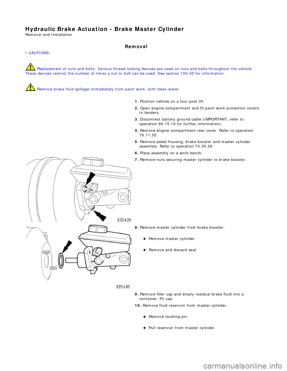
7. R
emove nuts securing master cylinder to brake booster.
8. R
emove master cylinder from brake booster.
Re
move master cylinder.
Remove an
d discard seal.
9. Remove filler cap and empty residual brake fluid into a
container. Fit cap.
10. Remove fluid reservoir from master cylinder.
R
emove locating pin.
Pull
reservoir from master cylinder.
Page 414 of 2490
Hydrau
lic Brake Actuation - Brake Pedal and Bracket
Re
mo
val and Installation
Remov
a
l
• C
A
UTIONS:
Replacement of nuts and bolts: Various thread-locking de vices are used on nuts and bolts throughout the vehicle.
These devices restrict the number of times a nut or bolt can be used. See section 100-00 for information.
Remove brake fluid spilla ge immediately from paint work, with clean water.
In
stallation
1.
Position vehicl
e on a four-post lift.
2. Open hood and fit suitable pa intwork protection equipment.
3. Disconnect battery ground cabl e. (IMPORTANT, see 86.15.19
for further information).
4. Remove engine compartment rear cover. Refer to operation
76.11.35.
5. Remove pedal housing, brake booster and master cylinder
assembly. Refer to operation 70.35.39.
6. Remove brake booster and master cylinder assembly. Refer to
operation 70.50.18.
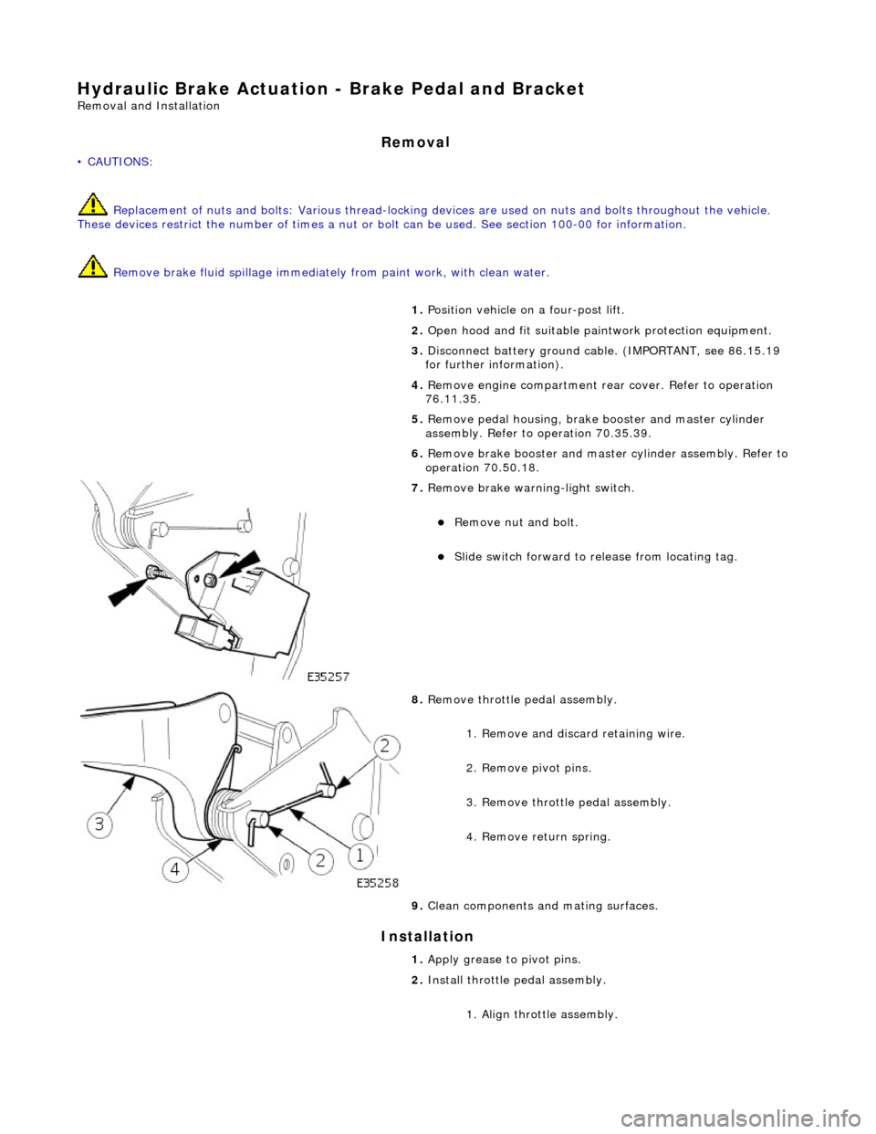
7. Remove brake wa
rning-light switch.
Remove n
u
t and bolt.
Slide sw
itch forward to release from locating tag.
8. Re
move throttle pedal assembly.
1. Remove and discard retaining wire.
2. Remove pivot pins.
3. Remove throttle pedal assembly.
4. Remove return spring.
9. Clean components and mating surfaces.
1. Apply grease to pivot pins.
2. Install throttle pedal assembly.
1. Align throttle assembly.
Page 416 of 2490
Hydrau
lic Brake Actuation - Brake Pedal and Bracket, Brake Booster and
Brake Master Cylinder
Re mo
val and Installation
Remova
l
• C
A
UTIONS:
Replacement of nuts and bolts: Various thread-locking de vices are used on nuts and bolts throughout the vehicle.
These devices restrict the number of times a nut or bolt can be used. See section 100-00 for information.
Remove brake fluid spilla ge immediately from paint work, with clean water.
1. Position vehi cl
e on a four-post lift.
2. Open engine compartment and fit paint work protection covers
to fenders.
3. Disconnect battery ground cable (IMPORTANT, refer to
operation 86.15.19 for fu rther information).
4. Remove engine compartment rear cover. Refer to operation
76.11.35.
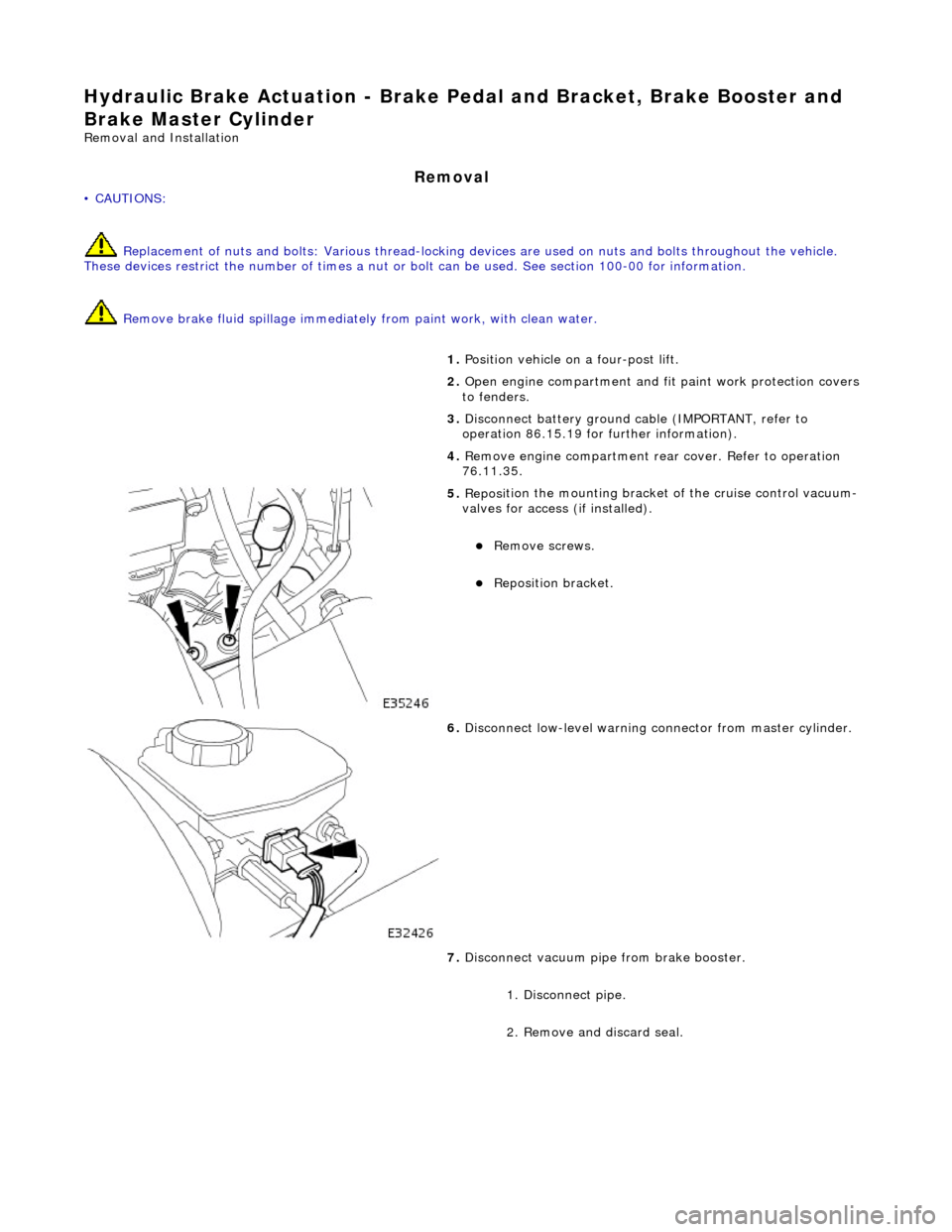
5. Reposi
tion the mounting bracket of the cruise control vacuum-
valves for access (if installed).
R e
move screws.
Reposition bracket.
6. Disc
onnect low-level warning connector from master cylinder.
7. Disconnect vacuum pipe from brake booster.
1. Disconnect pipe.
2. Remove and discard seal.
Page 423 of 2490
Power Brake Actuatio
n - Brake Booster
Re
moval and Installation
Remov
al
• C
AUTIONS:
Replacement of nuts and bolts: Various thread-locking de vices are used on nuts and bolts throughout the vehicle.
These devices restrict the number of times a nut or bolt can be used. See section 100-00 for information.
Remove brake fluid spilla ge immediately from paint work, with clean water.
I
nstallation
1.
Position vehi
cle on a four-post lift.
2. Open engine compartment and fit paint work protection covers
to fenders.
3. Disconnect battery ground cable (IMPORTANT, see operation
86.15.19 for further information).
4. Remove engine compartment rear cover. Refer to operation
76.11.35.
5. Remove pedal housing, brake booster and master cylinder
assembly. Refer to operation 70.35.39.
6. Remove brake booster and master cylinder assembly. Refer to
operation 70.50.18.
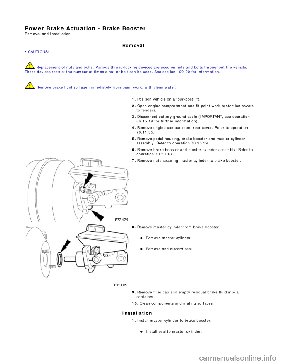
7. R
emove nuts securing master cylinder to brake booster.
8. R
emove master cylinder from brake booster.
Re
move master cylinder.
Remove an
d discard seal.
9. Remove filler cap and empty residual brake fluid into a
container.
10. Clean components and mating surfaces.
1. Install master cylinder to brake booster.
Inst
all seal to master cylinder.
Page 425 of 2490
Power Brake Actuatio
n - Brake Boos
ter and Brake Master Cylinder
Re
moval and Installation
Remov
al
• C
AUTIONS:
Replacement of nuts and bolts: Various thread-locking de vices are used on nuts and bolts throughout the vehicle.
These devices restrict the number of times a nut or bolt can be used. See section 100-00 for information.
Remove brake fluid spilla ge immediately from paint work, with clean water.
1. Position vehi
cle on a four-post lift.
2. Move driver's seat fully rearward.
3. Open engine compartment and fit paint work protection covers
to fenders.
4. Disconnect battery ground cable (IMPORTANT, see operation
86.15.19 for further information).
5. Remove engine compartment rear cover. Refer to operation
76.11.35.
6. Remove pedal housing, brake booster and master cylinder
assembly. Refer to operation 70.35.39.
7. Remove reservoir filler cap and po ur residual brake fluid into a
container. Refit cap.
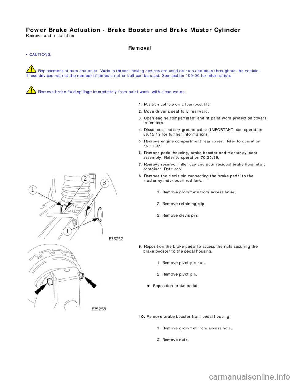
8. R
emove the clevis pin connecting the brake pedal to the
master cylinder push-rod fork.
1. Remove grommets from access holes.
2. Remove retaining clip.
3. Remove clevis pin.
9. Re
position the brake pedal to access the nuts securing the
brake booster to the pedal housing.
1. Remove pivot pin nut.
2. Remove pivot pin.
Reposition brake pedal.
10
.
Remove brake booster from pedal housing.
1. Remove grommet from access hole.
2. Remove nuts.
Page 440 of 2490
Anti-Lock Control - Anti-Lock Brake System (ABS) Module
Remo
val and Installation
Remov
a
l
• C
A
UTIONS:
Replacement of nuts and bolts: Various thread-locking de vices are used on nuts and bolts throughout the vehicle.
These devices restrict the number of times a nut or bolt can be used. See section 100-00 for information.
Remove brake fluid spilla ge immediately from paint work, with clean water.
Sp
ecial Tool(s)
Brake Pedal
H
old Tool
JDS 9013
1. Disc onne
ct battery ground cable (IMPORTANT, see operation
86.15.19 for further information).
2. Position vehicle on a four-post lift.
3. Open engine compartment and fit paint work protection covers
to fenders.
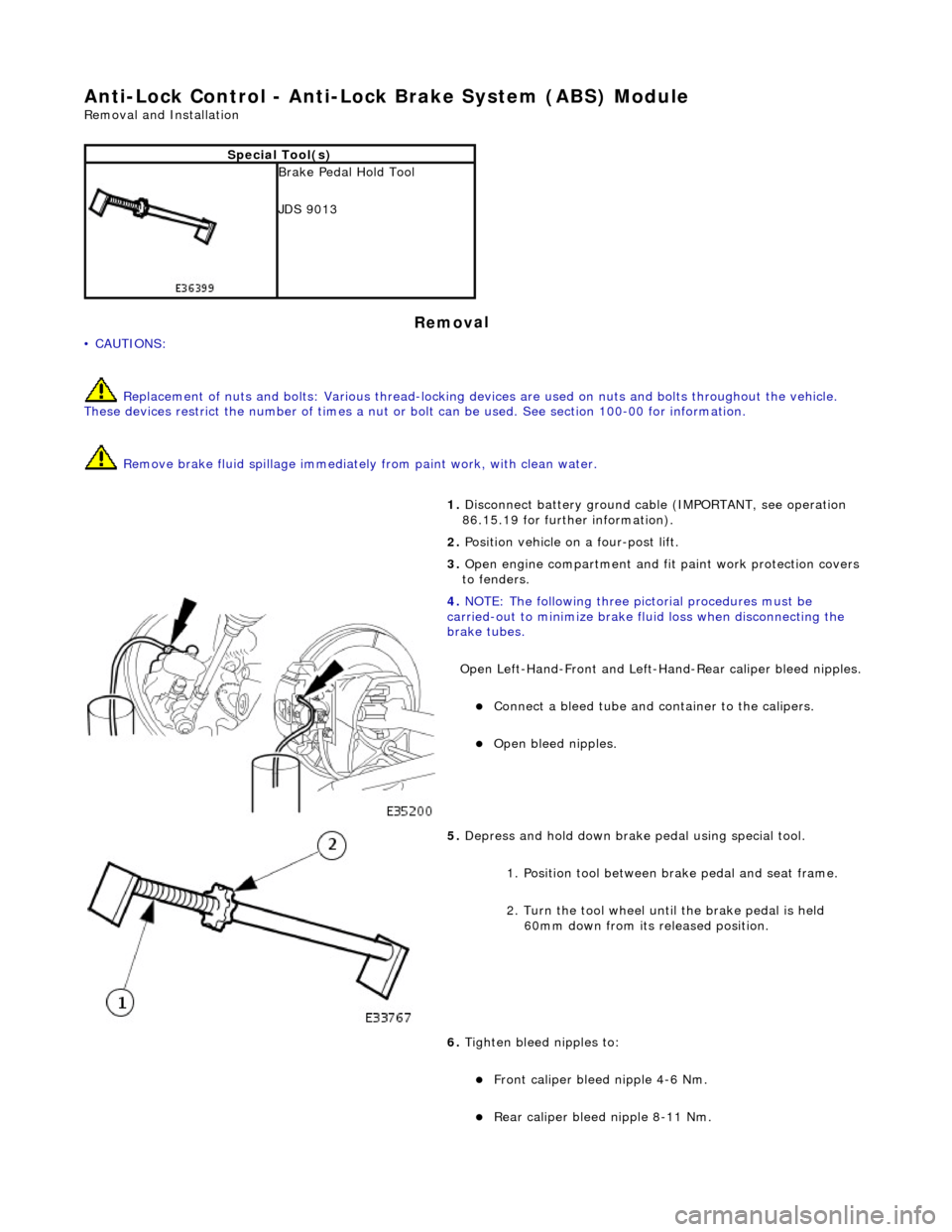
4. NOTE : Th
e following three pictorial procedures must be
carried-out to minimize brake fl uid loss when disconnecting the
brake tubes.
Open Left-Hand-Front and Left-H and-Rear caliper bleed nipples.
Connect a
bleed tube and co
ntainer to the calipers.
Op
en bleed nipples.
5. Depress and hold down brake pedal u s
ing special tool.
1. Position tool between brake pedal and seat frame.
2. Turn the tool wheel unti l the brake pedal is held
60mm down from its released position.
6. Tighten bleed nipples to:
Front caliper blee d nipple 4-6 Nm.
Rear
caliper bleed nip
ple 8-11 Nm.