tow points JAGUAR XF 2009 1.G Owners Manual
[x] Cancel search | Manufacturer: JAGUAR, Model Year: 2009, Model line: XF, Model: JAGUAR XF 2009 1.GPages: 391, PDF Size: 19.32 MB
Page 5 of 391
Contents
5
FUEL QUALITY .............................................. 174
ALTERNATIVE FUELS FOR PETROL ENGINES .....
175
DIESEL ENGINED VEHICLES......................... 176
RUNNING OUT OF FUEL ............................... 177
FUEL CUT-OFF .............................................. 177
FUEL FILLER FLAP........................................ 178
REFUELLING ................................................. 179
DIESEL MISFUELLING PROTECTION DEVICE......
180
FUEL CONSUMPTION ................................... 181
Load carrying
GENERAL INFORMATION ............................. 182
LUGGAGE ANCHOR POINTS ......................... 182
REAR UNDER FLOOR STORAGE ................... 182
Towing
TOWING A TRAILER (V6 petrol and diesel
vehicles only) ................................................ 183
LEVELLING ................................................... 184
RECOMMENDED TOWING WEIGHTS ........... 185
ESSENTIAL TOWING CHECKS ...................... 185
TOW BAR ...................................................... 186
Vehicle care
CLEANING THE ALLOY WHEELS .................. 187
CLEANING THE EXTERIOR ........................... 187
CLEANING THE INTERIOR ............................ 189
REPAIRING MINOR PAINT DAMAGE ............ 191
Maintenance
GENERAL INFORMATION ............................. 192
OPENING AND CLOSING THE BONNET ........ 195
ENGINE COMPARTMENT OVERVIEW ........... 196
ENGINE OIL CHECK - V6 Petrol engines ....... 197
ENGINE OIL CHECK - V8 Petrol engines ....... 199
ENGINE OIL CHECK - V6 Diesel engines ....... 201
ENGINE OIL SPECIFICATION ........................ 203
ENGINE COOLANT CHECK ............................ 204
BRAKE FLUID CHECK ................................... 206
POWER STEERING FLUID CHECK ................ 208
WASHER FLUID CHECK ................................ 209
TECHNICAL SPECIFICATIONS ...................... 210
Vehicle battery
BATTERY WARNING SYMBOLS ................... 212 BATTERY CARE ............................................ 212
USING BOOSTER CABLES ............................ 214
CHARGING THE VEHICLE BATTERY ............. 215
CHANGING THE VEHICLE BATTERY ............. 215
Wheels and tyres
GENERAL INFORMATION ............................. 216
TYRE CARE................................................... 217
USING WINTER TYRES ................................ 223
USING SNOW CHAINS ................................. 223
RUN FLAT TYRES ......................................... 224
TOOL KIT ...................................................... 224
CHANGING A ROAD WHEEL ......................... 225
TYRE REPAIR KIT......................................... 229
TYRE PRESSURE MONITORING SYSTEM.... 234
TYRE GLOSSARY ......................................... 238
TYRE SPECIFICATIONS - ARDUOUS TERRAIN ...
239
Fuses
CHANGING A FUSE....................................... 241
FUSE BOX LOCATIONS................................. 242
FUSE SPECIFICATION CHART ...................... 245
Emergency equipment
HAZARD WARNING FLASHERS.................... 250
WARNING TRIANGLE ................................... 250
FIRST AID KIT .............................................. 250
FIRE EXTINGUISHER .................................... 250
Status after a collision
DRIVING AFTER A COLLISION ..................... 251
INSPECTING SAFETY SYSTEM COMPONENTS ...
252
Vehicle recovery
TOWING POINTS .......................................... 253
TRANSPORTING THE VEHICLE .................... 254
TOWING THE VEHICLE ON FOUR WHEELS .. 256
Vehicle identification
VEHICLE IDENTIFICATION PLATE ................ 257
ENGINE NUMBER ......................................... 257
TRANSMISSION NUMBER ........................... 257
VEHICLE IDENTIFICATION
NUMBER (VIN)... 257
VEHICLE BUILD DATE PLATE ....................... 257
Page 7 of 391
Contents
7
MEMORY ...................................................... 353
AVOID POINTS.............................................. 355
HOME ........................................................... 355
DESTINATION ENTRY ................................... 356
POSTCODE ................................................... 357
MAP .............................................................. 357
COORDINATES ............................................. 357
MEMORY ...................................................... 358
PREVIOUS .................................................... 358
MOTORWAY ................................................. 359
COMPASS ..................................................... 360
POINTS OF INTEREST................................... 362
POI ICON DISPLAY ....................................... 363
CANCELLING POI ICON DISPLAY ................. 365
JAGUAR DEALERSHIP LOCATIONS.............. 365
ENTRY BY TOWN .......................................... 365
ENTRY BY CATEGORY .................................. 365
OTHER SELECTION METHODS ..................... 366
CATEGORIES AND SUB-CATEGORIES .......... 366
POI ENTRY MESSAGES ................................ 366
QUICK POI SELECTION ................................. 366
SELECTING A QUICK POI CATEGORY........... 367
MEMORY POINTS ......................................... 367
RDS-TMC OVERVIEW ................................... 368
USING TMC .................................................. 370
SURVEILLANCE SETTING ............................. 372
USING VOICE CONTROL ............................... 373
NAVIGATION SYSTEM VOICE COMMANDS .. 374
ORDNANCE SURVEY DATA .......................... 378
NAVTEQ CORPORATION............................... 379
EUROPEAN DECLARATION OF CONFORMITY .....
380
Page 64 of 391
Child safety
64
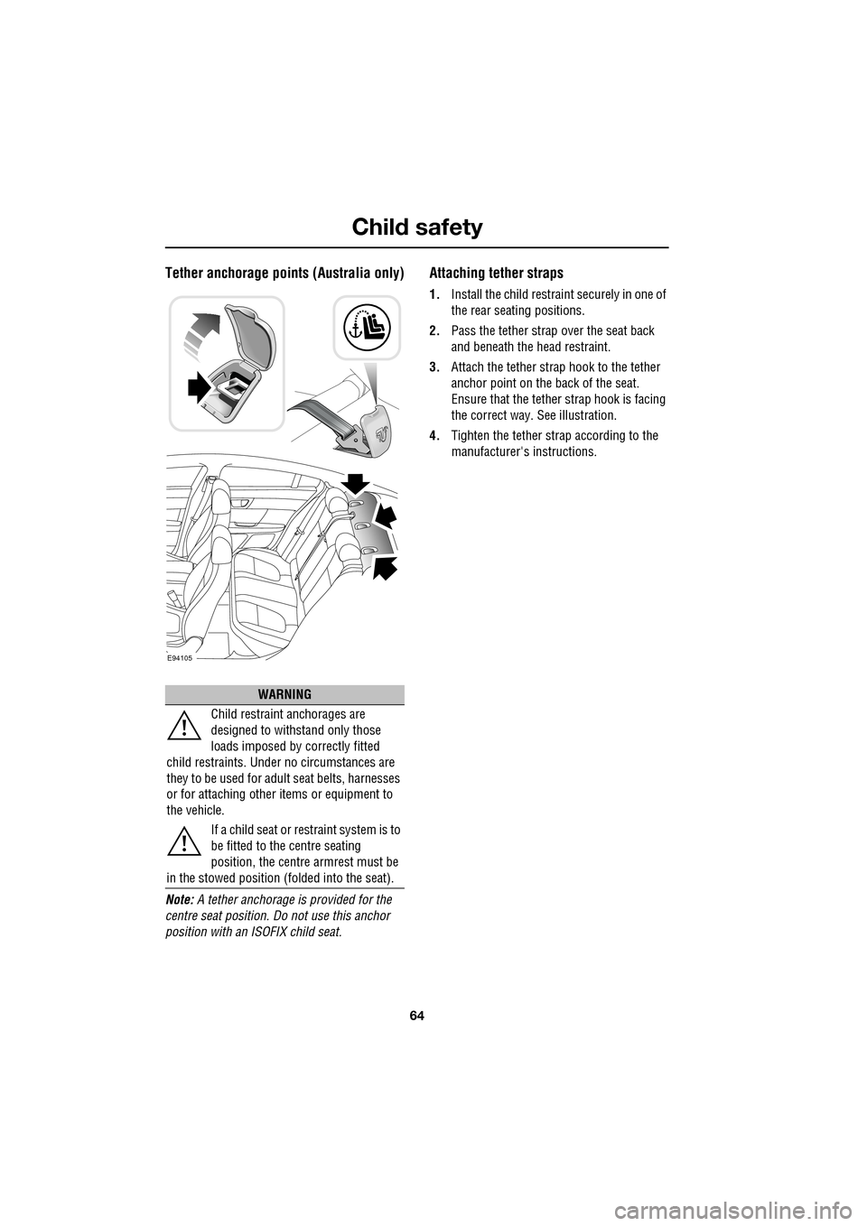
Tether anchorage points (Australia only)
Note: A tether anchorage is provided for the
centre seat position. Do not use this anchor
position with an ISOFIX child seat.
Attaching tether straps
1. Install the child restrain t securely in one of
the rear seating positions.
2. Pass the tether strap over the seat back
and beneath the head restraint.
3. Attach the tether strap hook to the tether
anchor point on the back of the seat.
Ensure that the tether strap hook is facing
the correct way. See illustration.
4. Tighten the tether strap according to the
manufacturer's instructions.
WARNING
Child restraint anchorages are
designed to withstand only those
loads imposed by correctly fitted
child restraints. Under no circumstances are
they to be used for adult seat belts, harnesses
or for attaching other items or equipment to
the vehicle.
If a child seat or restraint system is to
be fitted to the centre seating
position, the centre armrest must be
in the stowed position (folded into the seat).
E94105
Page 138 of 391
Transmission
138
P should be selected before switching off the
engine. However, it is possible to switch the
engine off with R, D or S selected - the selector
will automatica lly select P, while retracting into
the centre console.
Note: If the engine is switched off with N
selected, the system will wait for 10 minutes
before selecting P. This procedure is to allow
the vehicle to be conveyed through a car wash
only and should not be used for vehicle
recovery purposes.
To prevent the transmission from
automatically selecting P (e.g. for vehicle
recovery purposes), it is necessary to activate
the Emergency Park Release.
See TRANSPORTING THE VEHICLE
(page 254).
Selector positions
P - Park: Use when parked. In this position the
transmission is locked, do not attempt to select
P if the vehicle is moving.
Note: P will be selected automatically when the
engine is switched off.
R - Reverse: Do not select if the vehicle is
moving forward.
N - Neutral: Disconnects drive to the wheels.
Use the parking brake when stopping
temporarily with N selected.
D - Drive: Gear changing is automatic for all six
forward gears. The shift points are determined
by accelerator pedal pos ition and road speed,
to provide the best ba lance of performance,
refinement and fuel economy, for the large
majority of driving conditions.
S - Sport: Gear changing is automatic for all six
forward gears, with modified gear shift points
to maximise the ve hicle response in
demanding driving condi tions. This mode is
not suitable for town or highway cruising. Note:
Both D and S positions also offer
additional features, wh ich are listed under
Automatic mode and Sport mode , later in this
section.
Stationary vehicle
When the vehicle is stationary, the selector
may be left in D or S, unless the vehicle is to be
parked. When stopping fo r extended periods,
either select P or apply the parking brake and
select N.
Selector interlock
The transmission is equippe d with an interlock,
to prevent inadvertent selection of a drive gear
(D , S or R) from the P or N positions. To
release the interlock to select a drive gear,
press the brake pedal while making the
selection.
Ensure the required driv ing range has selected
prior to releasing the brake pedal. The range
indicator ( R, D or S) on the selector and
message centre disp lays, will illuminate
continuously to confirm selection.
Note: If the brake pedal is released too early
during selector rotation from P or N to a driving
range ( R, D or S), then the selected range will
not be engaged. The selected range will flash
on the selector and message centre displays.
To obtain the selected range, press the brake
pedal, select P or N and reselect the required
range, ensuring the brake pedal is depressed.
If N is selected for less than 2 seconds (e.g.
when moving the selector between R and D),
the interlock will not ac tivate and the brake
pedal will not need to be pressed.
Note: The interlock is deactivated when the
vehicle is travelling at more than 5 km/h
(3 mph).
Page 183 of 391
183
Towing
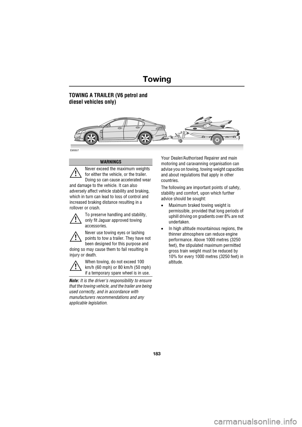
TOWING A TRAILER (V6 petrol and
diesel vehicles only)
Note: It is the driver's responsibility to ensure
that the towing vehicle, and the trailer are being
used correctly, and in accordance with
manufacturers recommendations and any
applicable legislation. Your Dealer/Authorised Repairer and main
motoring and caravanni
ng organisation can
advise you on towing, towing weight capacities
and about regulations that apply in other
countries.
The following are important points of safety,
stability and comfort, upon which further
advice should be sought:
• Maximum braked towing weight is
permissible, provided that long periods of
uphill driving on gradients over 8% are not
undertaken.
• In high altitude mount ainous regions, the
thinner atmosphere can reduce engine
performance. Abov e 1000 metres (3250
feet), the stipulated maximum permitted
gross train weight mu st be reduced by
10% for every 1000 metres (3250 feet) in
altitude.
E95507
WARNINGS
Never exceed the maximum weights
for either the vehicle, or the trailer.
Doing so can cause accelerated wear
and damage to the ve hicle. It can also
adversely affect vehicle stability and braking,
which in turn can lead to loss of control and
increased braking distance resulting in a
rollover or crash.
To preserve handling and stability,
only fit Jaguar approved towing
accessories.
Never use towing eyes or lashing
points to tow a trailer. They have not
been designed for this purpose and
doing so may cause them to fail resulting in
injury or death.
When towing, do not exceed 100
km/h (60 mph) or 80 km/h (50 mph)
if a temporary spare wheel is in use.
Page 186 of 391
Towing
186
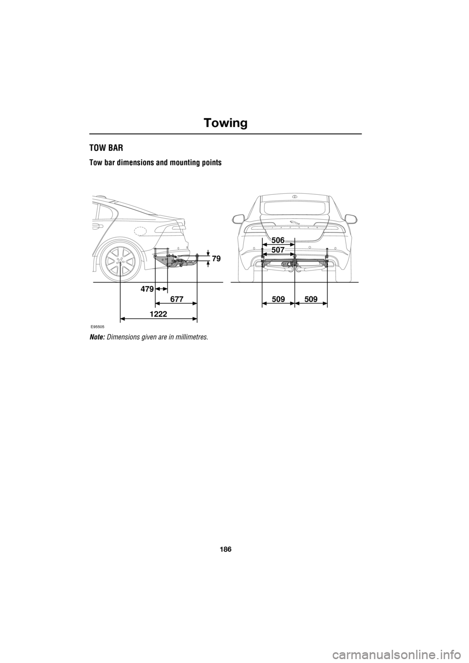
TOW BAR
Tow bar dimensions and mounting points
Note: Dimensions given ar e in millimetres.
E95505
479
677 509 509
1222 79
506
507
Page 253 of 391
253
Vehicle recovery
TOWING POINTS
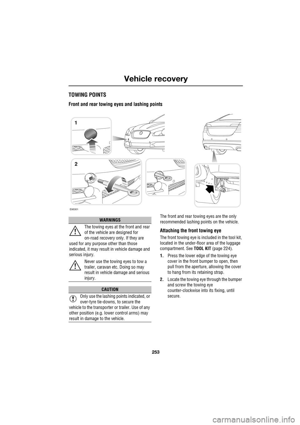
Front and rear towing eyes and lashing points
The front and rear towing eyes are the only
recommended lashing points on the vehicle.
Attaching the front towing eye
The front towing eye is included in the tool kit,
located in the under-floor area of the luggage
compartment. See TOOL KIT (page 224).
1. Press the lower edge of the towing eye
cover in the front bumper to open, then
pull from the aperture, allowing the cover
to hang from its retaining strap.
2. Locate the towing eye through the bumper
and screw the towing eye
counter-clockwise into its fixing, until
secure.
E95301
1
2
WARNINGS
The towing eyes at the front and rear
of the vehicle are designed for
on-road recovery only. If they are
used for any purpose other than those
indicated, it may result in vehicle damage and
serious injury.
Never use the towing eyes to tow a
trailer, caravan etc. Doing so may
result in vehicle damage and serious
injury.
CAUTION
Only use the lashing points indicated, or
over-tyre tie-downs, to secure the
vehicle to the transporter or trailer. Use of any
other position (e.g. lower control arms) may
result in damage to the vehicle.
Page 256 of 391
Vehicle recovery
256
TOWING THE VEHICLE ON FOUR
WHEELS
Note: The recommended recovery method is
to raise all four wheels.
Towing procedure
1. The vehicle should be parked on firm level
ground, with the parking brake on, and the
gear selector in P (Park).
2. Secure the towing attachment from the
recovery vehicle to the front towing eye.
See TOWING POINTS (page 253).
3. Dock the Jaguar Smart Key and switch on
the ignition. See GENERAL INFORMATION
(page 132). 4.
Apply the foot brake and release the
parking brake.
5. With the foot brake st ill applied, activate
the Emergency Park Release (EPR).
See TRANSPORTING THE VEHICLE
(page 254).
6. The vehicle can now be towed a maximum
of 0.8 km (0.5 miles) at a maximum speed
of 48 kmh (30 mph).
7. Upon arrival at the destination, ensure
wherever possible that the vehicle is
parked on firm level ground.
8. Lower the Emergency Park Release (EPR)
lever, to cancel EP R and to re-engage P
(Park).
9. Apply the parking brake.
10. Switch off the ignition and remove the
Jaguar Smart Key.
11. Remove the towing attachment from the
towing eye.
WARNINGS
Ensure that the remote control
remains docked whilst the vehicle is
being towed. Removing the remote
control will engage the steering lock, which
will prevent the vehicle from steering
correctly.
If the engine cannot be run whilst the
vehicle is being towed, there will be
no power assistance for the steering
or brakes. This will result in greater effort
being required to steer or slow the vehicle, and
greatly increased stopping distances.
CAUTIONS
The vehicle should only be towed in a
forward direction with all four wheels on
the ground.
The vehicle should only be towed for a
maximum of 0.8 km (0.5 miles), at a
maximum speed of 48 km/h (30 mph). Towing
for a greater distance or at a higher speed, may
result in serious damage to the transmission.
CAUTION
Leaving the ignition switched on for
extended periods will cause the battery
to drain.
WARNING
Use extreme caution when detaching
towing equipment. Vehicle movement
is possible which can result in serious
injuries.
Page 337 of 391
337
Navigation system
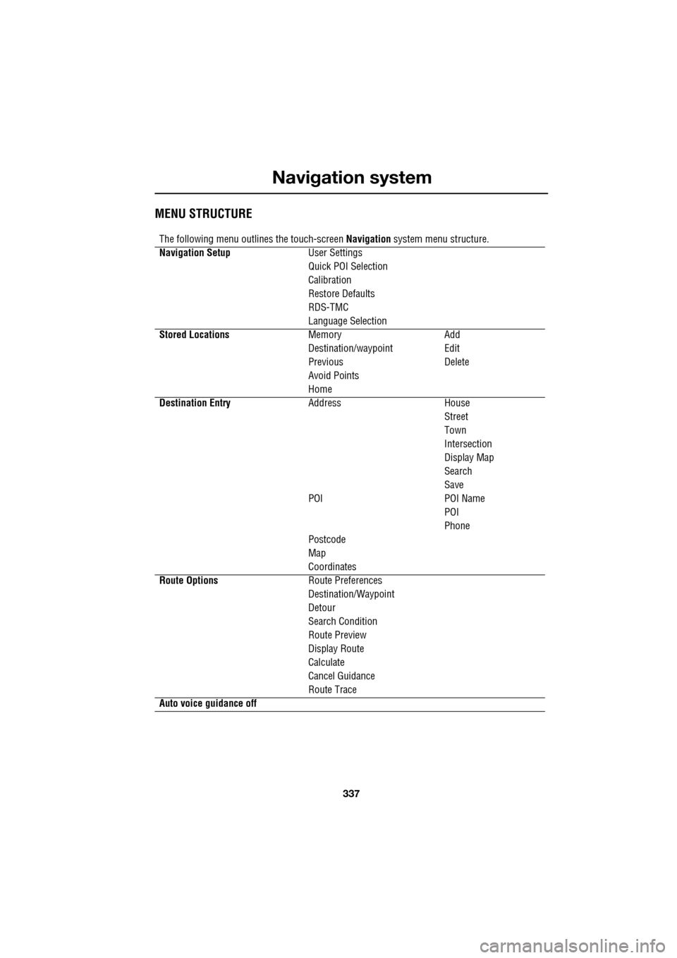
MENU STRUCTURE
The following menu outlines the touch-screen Navigation system menu structure.
Navigation Setup User Settings
Quick POI Selection
Calibration
Restore Defaults
RDS-TMC
Language Selection
Stored Locations Memory Add
Destination/waypointEdit
Previous Delete
Avoid Points
Home
Destination Entry AddressHouse
Street
Town
Intersection
Display Map
Search
Save
POI POI Name
POI
Phone
Postcode
Map
Coordinates
Route Options Route Preferences
Destination/Waypoint
Detour
Search Condition
Route Preview
Display Route
Calculate
Cancel Guidance
Route Trace
Auto voice guidance off
Page 342 of 391
Navigation system
342
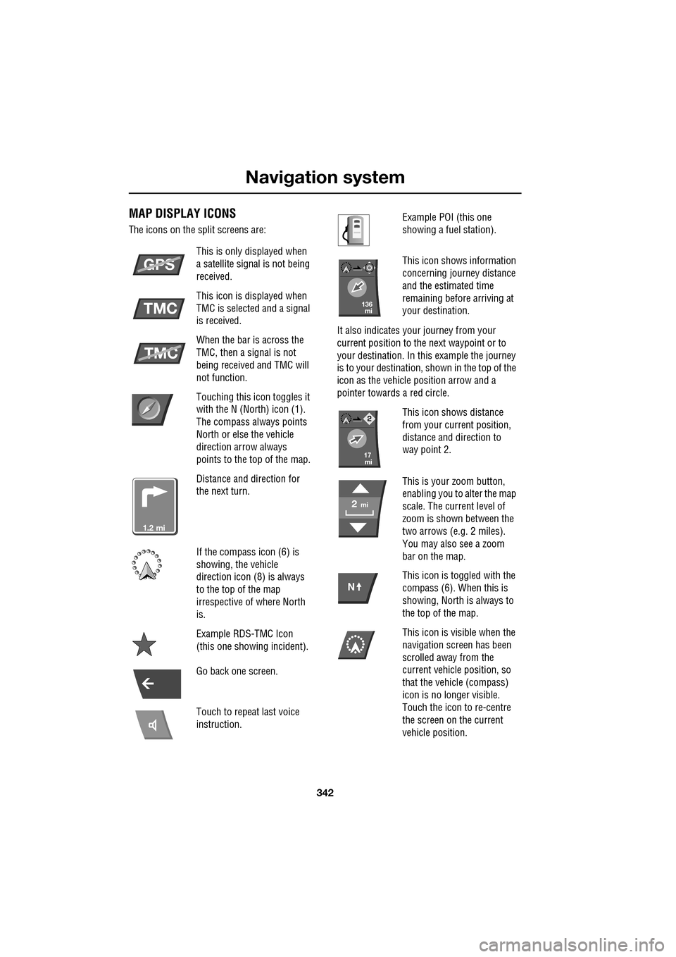
MAP DISPLAY ICONS
The icons on the split screens are:This is only displayed when
a satellite signal is not being
received.
This icon is displayed when
TMC is selected and a signal
is received.
When the bar is across the
TMC, then a signal is not
being received and TMC will
not function.
Touching this icon toggles it
with the N (North) icon (1).
The compass always points
North or else the vehicle
direction arrow always
points to the top of the map.
Distance and direction for
the next turn.
If the compass icon (6) is
showing, the vehicle
direction icon (8) is always
to the top of the map
irrespective of where North
is.
Example RDS-TMC Icon
(this one showing incident).
Go back one screen.
Touch to repeat last voice
instruction.
GPS
TMC
TMC
mi1.2
Example POI (this one
showing a fuel station).
This icon shows information
concerning journey distance
and the estimated time
remaining before arriving at
your destination.
It also indicates your journey from your
current position to the next waypoint or to
your destination. In th is example the journey
is to your destination, shown in the top of the
icon as the vehicle position arrow and a
pointer towards a red circle.
This icon shows distance
from your current position,
distance and direction to
way point 2.
This is your zoom button,
enabling you to alter the map
scale. The current level of
zoom is shown between the
two arrows (e.g. 2 miles).
You may also see a zoom
bar on the map.
This icon is toggled with the
compass (6). When this is
showing, North is always to
the top of the map.
This icon is visible when the
navigation screen has been
scrolled away from the
current vehicle position, so
that the vehicle (compass)
icon is no longer visible.
Touch the icon to re-centre
the screen on the current
vehicle position.
mi136
mi17
mi2
N