fuse chart JAGUAR XFR 2010 1.G Workshop Manual
[x] Cancel search | Manufacturer: JAGUAR, Model Year: 2010, Model line: XFR, Model: JAGUAR XFR 2010 1.GPages: 3039, PDF Size: 58.49 MB
Page 653 of 3039
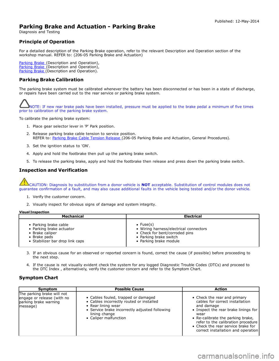
Parking Brake and Actuation - Parking Brake
Diagnosis and Testing
Principle of Operation Published: 12-May-2014
For a detailed description of the Parking Brake operation, refer to the relevant Description and Operation section of the
workshop manual. REFER to: (206-05 Parking Brake and Actuation)
Parking Brake (Description and Operation), Parking Brake (Description and Operation), Parking Brake (Description and Operation).
Parking Brake Calibration
The parking brake system must be calibrated whenever the battery has been disconnected or has been in a state of discharge,
or repairs have been carried out to the rear service or parking brake system.
NOTE: If new rear brake pads have been installed, pressure must be applied to the brake pedal a minimum of five times
prior to calibration of the parking brake system.
To calibrate the parking brake system:
1. Place gear selector lever in 'P' Park position.
2. Release parking brake cable tension to service position.
REFER to: Parking Brake Cable Tension Release (206-05 Parking Brake and Actuation, General Procedures).
3. Set the ignition status to 'ON'.
4. Apply and hold the footbrake then pull up the parking brake switch.
5. To release the parking brake, apply and hold the footbrake then release and press down the parking brake switch.
Inspection and Verification
CAUTION: Diagnosis by substitution from a donor vehicle is NOT acceptable. Substitution of control modules does not
guarantee confirmation of a fault, and may also cause additional faults in the vehicle being tested and/or the donor vehicle.
1. Verify the customer concern.
2. Visually inspect for obvious signs of damage and system integrity.
Visual Inspection
Mechanical Electrical
Parking brake cable
Parking brake actuator
Brake caliper
Brake pads
Stabilizer bar drop link caps
Fuse(s)
Wiring harness/electrical connectors
Check for bent/corroded pins
Parking brake switch
Parking brake module
3. If an obvious cause for an observed or reported concern is found, correct the cause (if possible) before proceeding to
the next step.
4. If the cause is not visually evident check the system for any logged Diagnostic Trouble Codes (DTCs) and proceed to
the DTC Index , alternatively, verify the customer concern and refer to the Symptom Chart.
Symptom Chart
Symptom Possible Cause Action The parking brake will not
engage or release (with no
parking brake warning
message)
Cables fouled, trapped or damaged
Cables incorrectly routed or installed
Rear lining wear
Service brake incorrectly adjusted following
lining change
Caliper malfunction
Check the rear and primary
cables for correct installation
and damage
Inspect the rear brake linings for
wear
Re-calibrate the parking brake,
refer to the calibration procedure
Check the rear service brake for
correct installation and operation
Page 718 of 3039
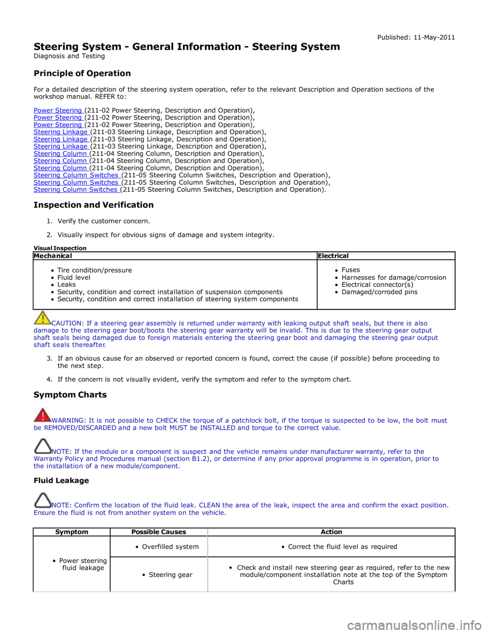
Steering System - General Information - Steering System
Diagnosis and Testing
Principle of Operation Published: 11-May-2011
For a detailed description of the steering system operation, refer to the relevant Description and Operation sections of the
workshop manual. REFER to:
Power Steering (211-02 Power Steering, Description and Operation), Power Steering (211-02 Power Steering, Description and Operation), Power Steering (211-02 Power Steering, Description and Operation), Steering Linkage (211-03 Steering Linkage, Description and Operation), Steering Linkage (211-03 Steering Linkage, Description and Operation), Steering Linkage (211-03 Steering Linkage, Description and Operation), Steering Column (211-04 Steering Column, Description and Operation), Steering Column (211-04 Steering Column, Description and Operation), Steering Column (211-04 Steering Column, Description and Operation), Steering Column Switches (211-05 Steering Column Switches, Description and Operation), Steering Column Switches (211-05 Steering Column Switches, Description and Operation), Steering Column Switches (211-05 Steering Column Switches, Description and Operation).
Inspection and Verification
1. Verify the customer concern.
2. Visually inspect for obvious signs of damage and system integrity.
Visual Inspection
Mechanical Electrical
Tire condition/pressure
Fluid level
Leaks
Security, condition and correct installation of suspension components
Security, condition and correct installation of steering system components
Fuses
Harnesses for damage/corrosion
Electrical connector(s)
Damaged/corroded pins
CAUTION: If a steering gear assembly is returned under warranty with leaking output shaft seals, but there is also
damage to the steering gear boot/boots the steering gear warranty will be invalid. This is due to the steering gear output
shaft seals being damaged due to foreign materials entering the steering gear boot and damaging the steering gear output
shaft seals thereafter.
3. If an obvious cause for an observed or reported concern is found, correct the cause (if possible) before proceeding to
the next step.
4. If the concern is not visually evident, verify the symptom and refer to the symptom chart.
Symptom Charts
WARNING: It is not possible to CHECK the torque of a patchlock bolt, if the torque is suspected to be low, the bolt must
be REMOVED/DISCARDED and a new bolt MUST be INSTALLED and torque to the correct value.
NOTE: If the module or a component is suspect and the vehicle remains under manufacturer warranty, refer to the
Warranty Policy and Procedures manual (section B1.2), or determine if any prior approval programme is in operation, prior to
the installation of a new module/component.
Fluid Leakage
NOTE: Confirm the location of the fluid leak. CLEAN the area of the leak, inspect the area and confirm the exact position.
Ensure the fluid is not from another system on the vehicle.
Symptom Possible Causes Action
Power steering
fluid leakage
Overfilled system
Correct the fluid level as required
Steering gear
Check and install new steering gear as required, refer to the new
module/component installation note at the top of the Symptom
Charts
Page 720 of 3039
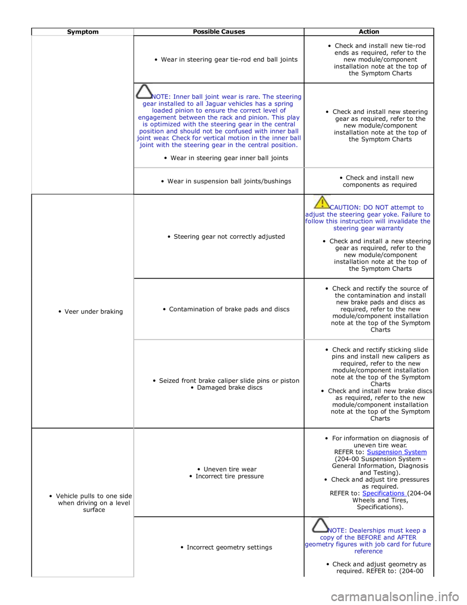
Symptom Possible Causes Action
Wear in steering gear tie-rod end ball joints
Check and install new tie-rod
ends as required, refer to the
new module/component
installation note at the top of
the Symptom Charts
NOTE: Inner ball joint wear is rare. The steering
gear installed to all Jaguar vehicles has a spring
loaded pinion to ensure the correct level of
engagement between the rack and pinion. This play
is optimized with the steering gear in the central
position and should not be confused with inner ball
joint wear. Check for vertical motion in the inner ball
joint with the steering gear in the central position.
Wear in steering gear inner ball joints
Check and install new steering
gear as required, refer to the
new module/component
installation note at the top of
the Symptom Charts
Wear in suspension ball joints/bushings
Check and install new
components as required
Veer under braking
Steering gear not correctly adjusted
CAUTION: DO NOT attempt to
adjust the steering gear yoke. Failure to
follow this instruction will invalidate the
steering gear warranty
Check and install a new steering
gear as required, refer to the
new module/component
installation note at the top of
the Symptom Charts
Contamination of brake pads and discs
Check and rectify the source of
the contamination and install
new brake pads and discs as
required, refer to the new
module/component installation
note at the top of the Symptom
Charts
Seized front brake caliper slide pins or piston
Damaged brake discs
Check and rectify sticking slide
pins and install new calipers as
required, refer to the new
module/component installation
note at the top of the Symptom
Charts
Check and install new brake discs
as required, refer to the new
module/component installation
note at the top of the Symptom
Charts
Vehicle pulls to one side
when driving on a level
surface
Uneven tire wear
Incorrect tire pressure
For information on diagnosis of
uneven tire wear.
REFER to: Suspension System (204-00 Suspension System -
General Information, Diagnosis
and Testing).
Check and adjust tire pressures
as required.
REFER to: Specifications (204-04 Wheels and Tires,
Specifications).
Incorrect geometry settings
NOTE: Dealerships must keep a
copy of the BEFORE and AFTER
geometry figures with job card for future
reference
Check and adjust geometry as
required. REFER to: (204-00
Page 811 of 3039
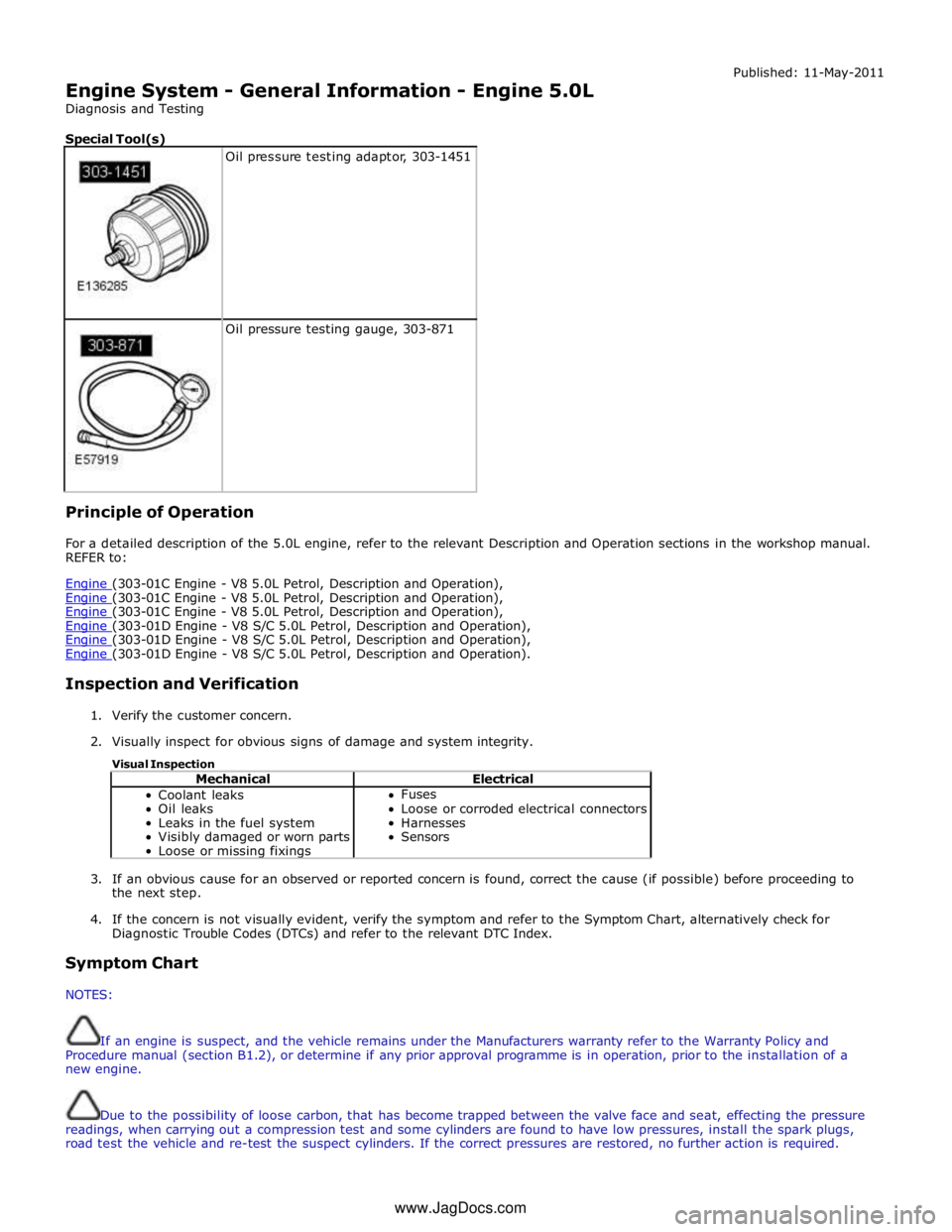
Engine System - General Information - Engine 5.0L
Diagnosis and Testing
Special Tool(s)
Oil pressure testing adaptor, 303-1451
Oil pressure testing gauge, 303-871 Principle of Operation Published: 11-May-2011
For a detailed description of the 5.0L engine, refer to the relevant Description and Operation sections in the workshop manual.
REFER to:
Engine (303-01C Engine - V8 5.0L Petrol, Description and Operation), Engine (303-01C Engine - V8 5.0L Petrol, Description and Operation), Engine (303-01C Engine - V8 5.0L Petrol, Description and Operation), Engine (303-01D Engine - V8 S/C 5.0L Petrol, Description and Operation), Engine (303-01D Engine - V8 S/C 5.0L Petrol, Description and Operation), Engine (303-01D Engine - V8 S/C 5.0L Petrol, Description and Operation).
Inspection and Verification
1. Verify the customer concern.
2. Visually inspect for obvious signs of damage and system integrity.
Visual Inspection
Mechanical Electrical Coolant leaks
Oil leaks
Leaks in the fuel system
Visibly damaged or worn parts
Loose or missing fixings Fuses
Loose or corroded electrical connectors
Harnesses
Sensors
3. If an obvious cause for an observed or reported concern is found, correct the cause (if possible) before proceeding to
the next step.
4. If the concern is not visually evident, verify the symptom and refer to the Symptom Chart, alternatively check for
Diagnostic Trouble Codes (DTCs) and refer to the relevant DTC Index.
Symptom Chart
NOTES:
If an engine is suspect, and the vehicle remains under the Manufacturers warranty refer to the Warranty Policy and
Procedure manual (section B1.2), or determine if any prior approval programme is in operation, prior to the installation of a
new engine.
Due to the possibility of loose carbon, that has become trapped between the valve face and seat, effecting the pressure
readings, when carrying out a compression test and some cylinders are found to have low pressures, install the spark plugs,
road test the vehicle and re-test the suspect cylinders. If the correct pressures are restored, no further action is required. www.JagDocs.com
Page 1122 of 3039
Published: 17-Apr-2014
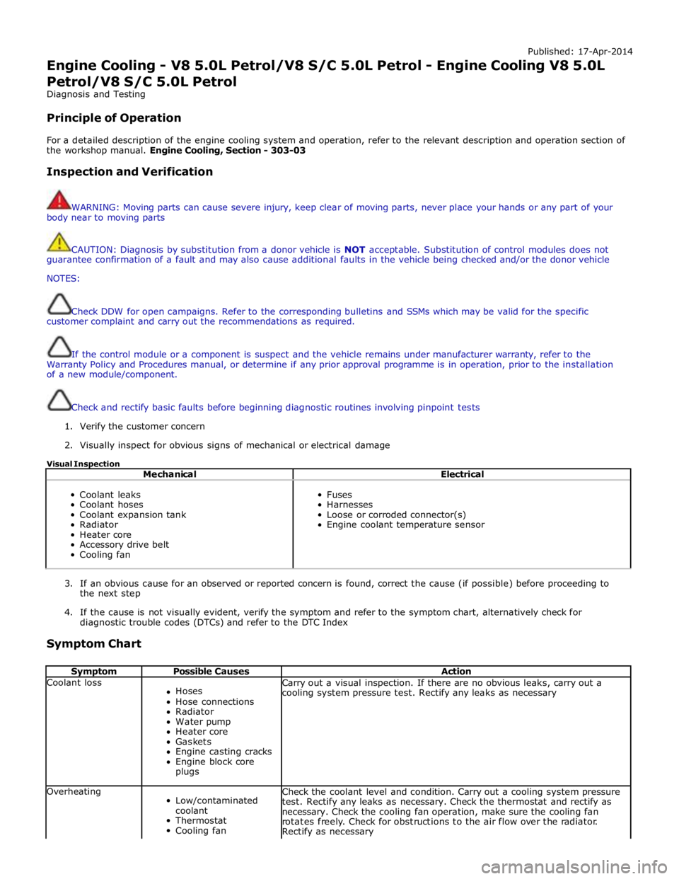
Engine Cooling - V8 5.0L Petrol/V8 S/C 5.0L Petrol - Engine Cooling V8 5.0L
Petrol/V8 S/C 5.0L Petrol
Diagnosis and Testing
Principle of Operation
For a detailed description of the engine cooling system and operation, refer to the relevant description and operation section of
the workshop manual. Engine Cooling, Section - 303-03
Inspection and Verification
WARNING: Moving parts can cause severe injury, keep clear of moving parts, never place your hands or any part of your
body near to moving parts
CAUTION: Diagnosis by substitution from a donor vehicle is NOT acceptable. Substitution of control modules does not
guarantee confirmation of a fault and may also cause additional faults in the vehicle being checked and/or the donor vehicle
NOTES:
Check DDW for open campaigns. Refer to the corresponding bulletins and SSMs which may be valid for the specific
customer complaint and carry out the recommendations as required.
If the control module or a component is suspect and the vehicle remains under manufacturer warranty, refer to the
Warranty Policy and Procedures manual, or determine if any prior approval programme is in operation, prior to the installation
of a new module/component.
Check and rectify basic faults before beginning diagnostic routines involving pinpoint tests
1. Verify the customer concern
2. Visually inspect for obvious signs of mechanical or electrical damage
Visual Inspection
Mechanical Electrical
Coolant leaks
Coolant hoses
Coolant expansion tank
Radiator
Heater core
Accessory drive belt
Cooling fan
Fuses
Harnesses
Loose or corroded connector(s)
Engine coolant temperature sensor
3. If an obvious cause for an observed or reported concern is found, correct the cause (if possible) before proceeding to
the next step
4. If the cause is not visually evident, verify the symptom and refer to the symptom chart, alternatively check for
diagnostic trouble codes (DTCs) and refer to the DTC Index
Symptom Chart
Symptom Possible Causes Action Coolant loss
Hoses
Hose connections
Radiator
Water pump
Heater core
Gaskets
Engine casting cracks
Engine block core
plugs Carry out a visual inspection. If there are no obvious leaks, carry out a
cooling system pressure test. Rectify any leaks as necessary Overheating
Low/contaminated
coolant
Thermostat
Cooling fan Check the coolant level and condition. Carry out a cooling system pressure
test. Rectify any leaks as necessary. Check the thermostat and rectify as
necessary. Check the cooling fan operation, make sure the cooling fan
rotates freely. Check for obstructions to the air flow over the radiator.
Rectify as necessary
Page 1187 of 3039
Published: 11-May-2011
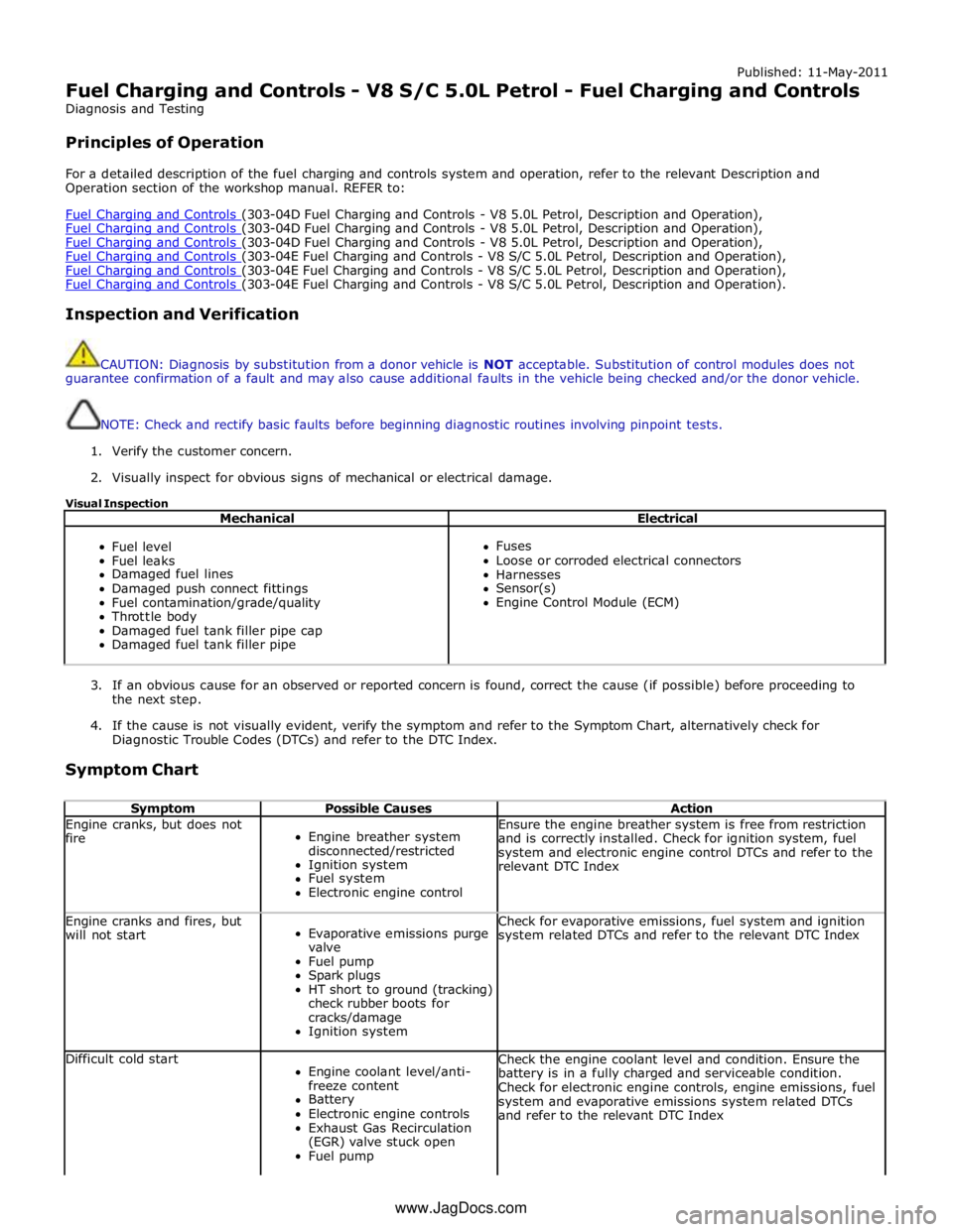
Fuel Charging and Controls - V8 S/C 5.0L Petrol - Fuel Charging and Controls
Diagnosis and Testing
Principles of Operation
For a detailed description of the fuel charging and controls system and operation, refer to the relevant Description and
Operation section of the workshop manual. REFER to:
Fuel Charging and Controls (303-04D Fuel Charging and Controls - V8 5.0L Petrol, Description and Operation), Fuel Charging and Controls (303-04D Fuel Charging and Controls - V8 5.0L Petrol, Description and Operation), Fuel Charging and Controls (303-04D Fuel Charging and Controls - V8 5.0L Petrol, Description and Operation), Fuel Charging and Controls (303-04E Fuel Charging and Controls - V8 S/C 5.0L Petrol, Description and Operation), Fuel Charging and Controls (303-04E Fuel Charging and Controls - V8 S/C 5.0L Petrol, Description and Operation), Fuel Charging and Controls (303-04E Fuel Charging and Controls - V8 S/C 5.0L Petrol, Description and Operation).
Inspection and Verification
CAUTION: Diagnosis by substitution from a donor vehicle is NOT acceptable. Substitution of control modules does not
guarantee confirmation of a fault and may also cause additional faults in the vehicle being checked and/or the donor vehicle.
NOTE: Check and rectify basic faults before beginning diagnostic routines involving pinpoint tests.
1. Verify the customer concern.
2. Visually inspect for obvious signs of mechanical or electrical damage.
Visual Inspection
Mechanical Electrical
Fuel level
Fuel leaks
Damaged fuel lines
Damaged push connect fittings
Fuel contamination/grade/quality
Throttle body
Damaged fuel tank filler pipe cap
Damaged fuel tank filler pipe
Fuses
Loose or corroded electrical connectors
Harnesses
Sensor(s)
Engine Control Module (ECM)
3. If an obvious cause for an observed or reported concern is found, correct the cause (if possible) before proceeding to
the next step.
4. If the cause is not visually evident, verify the symptom and refer to the Symptom Chart, alternatively check for
Diagnostic Trouble Codes (DTCs) and refer to the DTC Index.
Symptom Chart
Symptom Possible Causes Action Engine cranks, but does not
fire
Engine breather system
disconnected/restricted
Ignition system
Fuel system
Electronic engine control Ensure the engine breather system is free from restriction
and is correctly installed. Check for ignition system, fuel
system and electronic engine control DTCs and refer to the
relevant DTC Index Engine cranks and fires, but
will not start
Evaporative emissions purge
valve
Fuel pump
Spark plugs
HT short to ground (tracking)
check rubber boots for
cracks/damage
Ignition system Check for evaporative emissions, fuel system and ignition
system related DTCs and refer to the relevant DTC Index Difficult cold start
Engine coolant level/anti-
freeze content
Battery
Electronic engine controls
Exhaust Gas Recirculation
(EGR) valve stuck open
Fuel pump Check the engine coolant level and condition. Ensure the
battery is in a fully charged and serviceable condition.
Check for electronic engine controls, engine emissions, fuel
system and evaporative emissions system related DTCs
and refer to the relevant DTC Index www.JagDocs.com
Page 1263 of 3039
Published: 11-May-2011
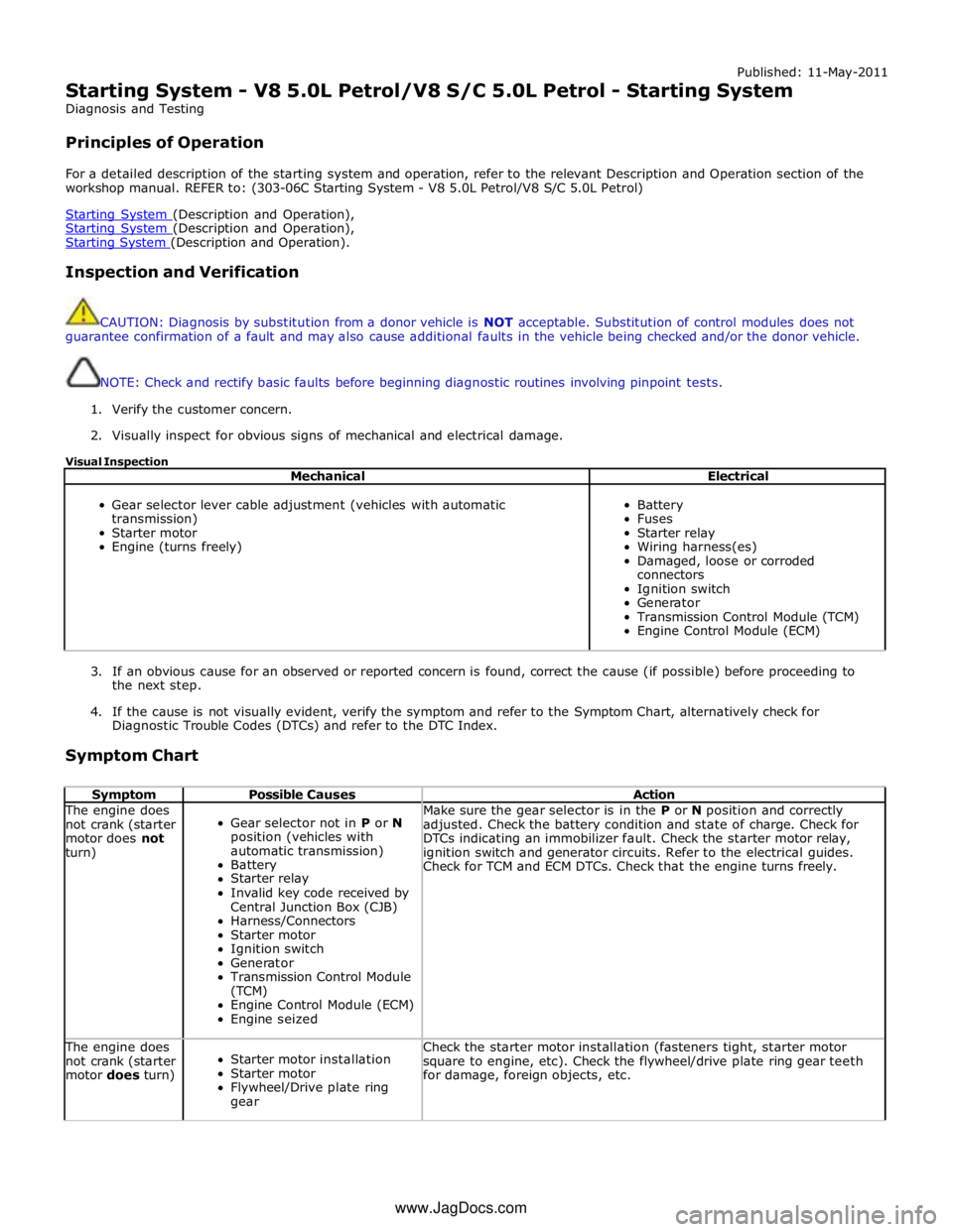
Starting System - V8 5.0L Petrol/V8 S/C 5.0L Petrol - Starting System
Diagnosis and Testing
Principles of Operation
For a detailed description of the starting system and operation, refer to the relevant Description and Operation section of the
workshop manual. REFER to: (303-06C Starting System - V8 5.0L Petrol/V8 S/C 5.0L Petrol)
Starting System (Description and Operation), Starting System (Description and Operation), Starting System (Description and Operation).
Inspection and Verification
CAUTION: Diagnosis by substitution from a donor vehicle is NOT acceptable. Substitution of control modules does not
guarantee confirmation of a fault and may also cause additional faults in the vehicle being checked and/or the donor vehicle.
NOTE: Check and rectify basic faults before beginning diagnostic routines involving pinpoint tests.
1. Verify the customer concern.
2. Visually inspect for obvious signs of mechanical and electrical damage.
Visual Inspection
Mechanical Electrical
Gear selector lever cable adjustment (vehicles with automatic
transmission)
Starter motor
Engine (turns freely)
Battery
Fuses
Starter relay
Wiring harness(es)
Damaged, loose or corroded
connectors
Ignition switch
Generator
Transmission Control Module (TCM)
Engine Control Module (ECM)
3. If an obvious cause for an observed or reported concern is found, correct the cause (if possible) before proceeding to
the next step.
4. If the cause is not visually evident, verify the symptom and refer to the Symptom Chart, alternatively check for
Diagnostic Trouble Codes (DTCs) and refer to the DTC Index.
Symptom Chart
Symptom Possible Causes Action The engine does
not crank (starter
motor does not
turn)
Gear selector not in P or N
position (vehicles with
automatic transmission)
Battery
Starter relay
Invalid key code received by
Central Junction Box (CJB)
Harness/Connectors
Starter motor
Ignition switch
Generator
Transmission Control Module
(TCM)
Engine Control Module (ECM)
Engine seized Make sure the gear selector is in the P or N position and correctly
adjusted. Check the battery condition and state of charge. Check for
DTCs indicating an immobilizer fault. Check the starter motor relay,
ignition switch and generator circuits. Refer to the electrical guides.
Check for TCM and ECM DTCs. Check that the engine turns freely. The engine does
not crank (starter
motor does turn)
Starter motor installation
Starter motor
Flywheel/Drive plate ring
gear Check the starter motor installation (fasteners tight, starter motor
square to engine, etc). Check the flywheel/drive plate ring gear teeth
for damage, foreign objects, etc. www.JagDocs.com
Page 1265 of 3039
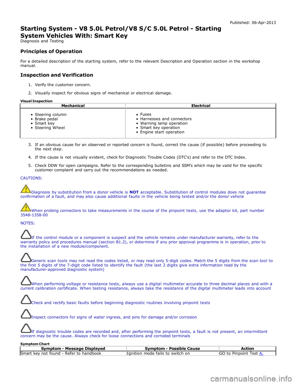
Starting System - V8 5.0L Petrol/V8 S/C 5.0L Petrol - Starting
System Vehicles With: Smart Key
Diagnosis and Testing
Principles of Operation Published: 06-Apr-2013
For a detailed description of the starting system, refer to the relevant Description and Operation section in the workshop
manual.
Inspection and Verification
1. Verify the customer concern.
2. Visually inspect for obvious signs of mechanical or electrical damage.
Visual Inspection
Mechanical Electrical
Steering column
Brake pedal
Smart key
Steering Wheel
Fuses
Harnesses and connectors
Warning lamp operation
Smart key operation
Engine start operation
3. If an obvious cause for an observed or reported concern is found, correct the cause (if possible) before proceeding to
the next step.
4. If the cause is not visually evident, check for Diagnostic Trouble Codes (DTC's) and refer to the DTC Index.
5. Check DDW for open campaigns. Refer to the corresponding bulletins and SSM's which may be valid for the specific
customer complaint and carry out the recommendations as needed.
CAUTIONS:
Diagnosis by substitution from a donor vehicle is NOT acceptable. Substitution of control modules does not guarantee
confirmation of a fault, and may also cause additional faults in the vehicle being tested and/or the donor vehicle
When probing connectors to take measurements in the course of the pinpoint tests, use the adaptor kit, part number
3548-1358-00
NOTES:
If the control module or a component is suspect and the vehicle remains under manufacturer warranty, refer to the
warranty policy and procedures manual (section B1.2), or determine if any prior approval programme is in operation, prior to
the installation of a new module/component.
Generic scan tools may not read the codes listed, or may read only 5-digit codes. Match the 5 digits from the scan tool to
the first 5 digits of the 7-digit code listed to identify the fault (the last 2 digits give extra information read by the
manufacturer-approved diagnostic system)
When performing voltage or resistance tests, always use a digital multimeter accurate to three decimal places and with a
current calibration certificate. When testing resistance, always take the resistance of the digital multimeter leads into account
Check and rectify basic faults before beginning diagnostic routines involving pinpoint tests
Inspect connectors for signs of water ingress, and pins for damage and/or corrosion
If diagnostic trouble codes are recorded and, after performing the pinpoint tests, a fault is not present, an intermittent
concern may be the cause. Always check for loose connections and corroded terminals
Symptom Chart
Symptom - Message Displayed Symptom - Possible Cause Action Smart key not found - Refer to handbook Ignition mode fails to switch on GO to Pinpoint Test A.
Page 1276 of 3039
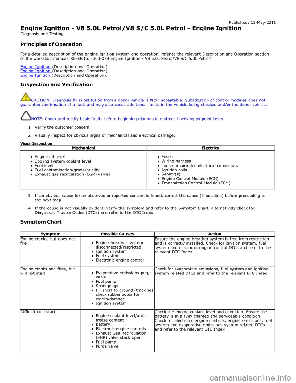
Published: 11-May-2011
Engine Ignition - V8 5.0L Petrol/V8 S/C 5.0L Petrol - Engine Ignition
Diagnosis and Testing
Principles of Operation
For a detailed description of the engine ignition system and operation, refer to the relevant Description and Operation section
of the workshop manual. REFER to: (303-07B Engine Ignition - V8 5.0L Petrol/V8 S/C 5.0L Petrol)
Engine Ignition (Description and Operation), Engine Ignition (Description and Operation), Engine Ignition (Description and Operation).
Inspection and Verification
CAUTION: Diagnosis by substitution from a donor vehicle is NOT acceptable. Substitution of control modules does not
guarantee confirmation of a fault and may also cause additional faults in the vehicle being checked and/or the donor vehicle.
NOTE: Check and rectify basic faults before beginning diagnostic routines involving pinpoint tests.
1. Verify the customer concern.
2. Visually inspect for obvious signs of mechanical and electrical damage.
Visual Inspection
Mechanical Electrical
Engine oil level
Cooling system coolant level
Fuel level
Fuel contamination/grade/quality
Exhaust gas recirculation (EGR) valves
Fuses
Wiring harness
Loose or corroded electrical connectors
Ignition coils
Sensor(s)
Engine Control Module (ECM)
Transmission Control Module (TCM)
3. If an obvious cause for an observed or reported concern is found, correct the cause (if possible) before proceeding to
the next step.
4. If the cause is not visually evident, verify the symptom and refer to the Symptom Chart, alternatively check for
Diagnostic Trouble Codes (DTCs) and refer to the DTC Index.
Symptom Chart
Symptom Possible Causes Action Engine cranks, but does not
fire
Engine breather system
disconnected/restricted
Ignition system
Fuel system
Electronic engine control Ensure the engine breather system is free from restriction
and is correctly installed. Check for ignition system, fuel
system and electronic engine control DTCs and refer to the
relevant DTC Index Engine cranks and fires, but
will not start
Evaporative emissions purge
valve
Fuel pump
Spark plugs
HT short to ground (tracking)
check rubber boots for
cracks/damage
Ignition system Check for evaporative emissions, fuel system and ignition
system related DTCs and refer to the relevant DTC Index Difficult cold start
Engine coolant level/anti-
freeze content
Battery
Electronic engine controls
Exhaust Gas Recirculation
(EGR) valve stuck open
Fuel pump
Purge valve Check the engine coolant level and condition. Ensure the
battery is in a fully charged and serviceable condition.
Check for electronic engine controls, engine emissions, fuel
system and evaporative emissions system related DTCs
and refer to the relevant DTC Index
Page 1283 of 3039
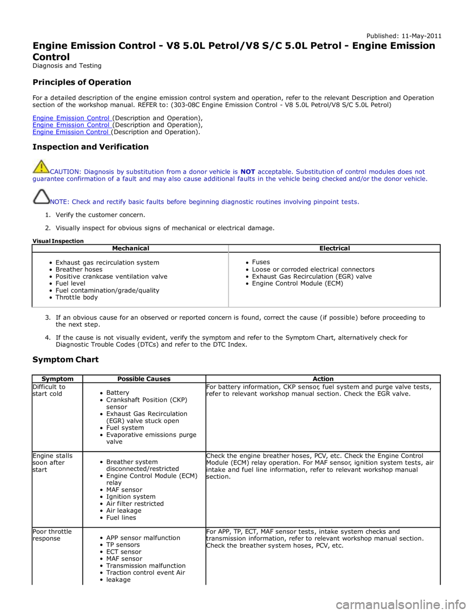
Published: 11-May-2011
Engine Emission Control - V8 5.0L Petrol/V8 S/C 5.0L Petrol - Engine Emission
Control
Diagnosis and Testing
Principles of Operation
For a detailed description of the engine emission control system and operation, refer to the relevant Description and Operation
section of the workshop manual. REFER to: (303-08C Engine Emission Control - V8 5.0L Petrol/V8 S/C 5.0L Petrol)
Engine Emission Control (Description and Operation), Engine Emission Control (Description and Operation), Engine Emission Control (Description and Operation).
Inspection and Verification
CAUTION: Diagnosis by substitution from a donor vehicle is NOT acceptable. Substitution of control modules does not
guarantee confirmation of a fault and may also cause additional faults in the vehicle being checked and/or the donor vehicle.
NOTE: Check and rectify basic faults before beginning diagnostic routines involving pinpoint tests.
1. Verify the customer concern.
2. Visually inspect for obvious signs of mechanical or electrical damage.
Visual Inspection
Mechanical Electrical
Exhaust gas recirculation system
Breather hoses
Positive crankcase ventilation valve
Fuel level
Fuel contamination/grade/quality
Throttle body
Fuses
Loose or corroded electrical connectors
Exhaust Gas Recirculation (EGR) valve
Engine Control Module (ECM)
3. If an obvious cause for an observed or reported concern is found, correct the cause (if possible) before proceeding to
the next step.
4. If the cause is not visually evident, verify the symptom and refer to the Symptom Chart, alternatively check for
Diagnostic Trouble Codes (DTCs) and refer to the DTC Index.
Symptom Chart
Symptom Possible Causes Action Difficult to
start cold
Battery
Crankshaft Position (CKP)
sensor
Exhaust Gas Recirculation
(EGR) valve stuck open
Fuel system
Evaporative emissions purge
valve For battery information, CKP sensor, fuel system and purge valve tests,
refer to relevant workshop manual section. Check the EGR valve. Engine stalls
soon after
start
Breather system
disconnected/restricted
Engine Control Module (ECM)
relay
MAF sensor
Ignition system
Air filter restricted
Air leakage
Fuel lines Check the engine breather hoses, PCV, etc. Check the Engine Control
Module (ECM) relay operation. For MAF sensor, ignition system tests, air
intake and fuel line information, refer to relevant workshop manual
section. Poor throttle
response
APP sensor malfunction
TP sensors
ECT sensor
MAF sensor
Transmission malfunction
Traction control event Air
leakage For APP, TP, ECT, MAF sensor tests, intake system checks and
transmission information, refer to relevant workshop manual section.
Check the breather system hoses, PCV, etc.