hub JAGUAR XFR 2010 1.G Workshop Manual
[x] Cancel search | Manufacturer: JAGUAR, Model Year: 2010, Model line: XFR, Model: JAGUAR XFR 2010 1.GPages: 3039, PDF Size: 58.49 MB
Page 4 of 3039

Four-Wheel Alignment
Front Toe Adjustment (57.65.01)
Rear Toe Adjustment (57.65.08)
Front Wheel Bearing and Wheel Hub Runout Check
Rear Wheel Bearing and Wheel Hub Runout Check204-01: Front SuspensionSpecificationDescription and OperationComponent Location
Overview
System Operation and Component DescriptionDiagnosis and TestingFront SuspensionRemoval and InstallationFront Shock Absorber (60.30.04)
Front Lower Arm (60.35.53)
Rear Lower Arm (60.35.54)
Rear Lower Arm Bushing (60.40.12)
Shock Absorber Bushing (60.30.16) (60.30.23)
Front Stabilizer Bar - V8 5.0L Petrol/V8 S/C 5.0L Petrol
Front Stabilizer Bar Link (60.10.02)
Stabilizer Bar Link Bushing (60.10.03)
Upper Arm LH (60.35.41)
Upper Arm RH (60.35.42)
Front Wheel Bearing and Wheel Hub - TDV6 3.0L Diesel /V8 5.0L Petrol/V8 S/C 5.0L Petrol
Wheel Knuckle (60.25.23)
Front Lower Arm Bushing204-02: Rear SuspensionSpecificationDescription and OperationComponent Location
Overview
System Operation and Component DescriptionDiagnosis and TestingRear SuspensionRemoval and InstallationLower Arm (64.35.43)
Shock Absorber and Spring Assembly
Shock Absorber Lower Bushing (64.30.39)
Rear Stabilizer Bar (64.35.08)
Rear Wheel Bearing
Upper Arm
Page 104 of 3039
Avoid brake testing on busy roads where it can cause inconvenience or danger to other road users.
CAUTION: Brake testing which includes heavy brake applications should not be carried out with new brake pads/discs or
linings/drums until the components have bedded-in. New brake friction components will not reach full efficiency until the
bedding-in process is complete.
Test the brakes at several speeds within the normal operating range using both light and heavy pedal pressure. Note any
tendency to snatch, pull or drag, and any undue delay in application or release.
Allow the vehicle to coast and note any tendency to pull to one side, or evidence that the brakes are binding.
After stopping the vehicle (not immediately after a period of heavy braking), carefully check the brake temperature. A disc
which feels hot, or appreciably hotter than the others, indicates that the brake is binding.
After completion of the test, check for:
Oil, coolant, hydraulic, air and fuel leaks
Abnormal temperature of any moving components or assemblies, e.g. wheel hubs, transmission, axle etc., which might
indicate over tightness or lack of lubrication
Page 300 of 3039
Noise Conditions
Gear noise is typically a howling or whining due to gear damage or incorrect bearing preload. It can occur at various
speeds and driving conditions, or it can be continuous
Chuckle is a particular rattling noise that sounds like a stick against the spokes of a spinning bicycle wheel. It occurs
while decelerating from approximately 64 km/h (40 miles/h) and can usually be heard all the way to a stop. The
frequency varies with vehicle speed
Knock is very similar to chuckle, though it may be louder and occurs on acceleration or deceleration. The tear down will
disclose what has to be corrected
Check and rule out tires, exhaust and trim items before disassembling the transmission to diagnose and correct gear noise.
The noises described under Road Test usually have specific causes that can be diagnosed by observation as the unit is
disassembled. The initial clues are the type of noise heard on the road test and the driving conditions.
Vibration Conditions
wear. NOTE: New Constant Velocity (CV) joints should not be installed unless disassembly and inspection revealed unusual
Clicking, popping or grinding noises may be caused by the following:
Cut or damaged CV joint boots resulting in inadequate or contaminated lubricant in the outboard or inboard CV joint
bearing housings
Loose CV joint boot clamps
Another component contacting the rear drive half shaft
Worn, damaged or incorrectly installed wheel bearing, suspension or brake component
Vibration at highway speeds may be caused by the following:
Out-of-balance front or rear wheels
Out-of-round tires
Driveline imbalance
Driveline run-out (alignment)
NOTE: Rear drive half shafts are not balanced and are not likely to contribute to rotational vibration disturbance.
Shudder or vibration during acceleration (including from rest) may be caused by the following:
Driveline alignment
Excessively worn or damaged outboard or inboard CV joint bearing housing
Excessively high CV joint operating angles caused by incorrect ride height. Check ride height, verify correct spring rate
and check items under Inoperative Conditions
Excessively worn driveshaft components
Leakage Conditions
1. Inspect the CV joint boots for evidence of cracks, tears or splits.
2. Inspect the underbody for any indication of grease splatter in the vicinity of the rear drive half shaft, outboard and
inboard CV joint boot locations, which is an indication of CV joint boot or CV joint boot clamp damage.
3. Inspect the inboard CV joint bearing housing seal for leakage.
Inoperative Conditions
If a CV joint or rear drive half shaft pull-out occurs, check the following:
suspension components for correct location, damage or wear
bushings for wear
subframe for damage
bent or worn components
- Stabilizer bar link
- Left-hand rear suspension lower arm and bushing
- Right-hand rear suspension lower arm and bushing
- Rear wheel hub and rear drive half shaft
Road Test
A gear-driven unit will produce a certain amount of noise. Some noise is acceptable and may be audible at certain speeds or
under various driving conditions as on a newly paved blacktop road. The slight noise is in no way detrimental and must be
considered normal.
The road test and customer interview (if available) provide information needed to identify the condition and give direction to
the correct starting point for diagnosis.
1. Make notes throughout the diagnosis routine. Make sure to write down even the smallest piece of information, because
Page 301 of 3039
it may turn out to be the most important.
2. Do not touch anything until a road test and a thorough visual inspection of the vehicle have been carried out. Leave the
tire pressures and vehicle load just where they were when the condition was first observed. Adjusting tire pressures,
vehicle load or making other adjustments may reduce the conditions intensity to a point where it cannot be identified
clearly. It may also inject something new into the system, preventing correct diagnosis.
3. Make a visual inspection as part of the preliminary diagnosis routine, writing down anything that does not look right.
Note tire pressures, but do not adjust them yet. Note leaking fluids, loose nuts and bolts, or bright spots where
components may be rubbing against each other. Check the luggage compartment for unusual loads.
4. Road test the vehicle and define the condition by reproducing it several times during the road test.
5. Carry out the Road Test Quick Checks as soon as the condition is reproduced. This will identify the correct diagnostic
procedure. Carry out the Road Test Quick Checks more than once to verify they are providing a valid result. Remember,
the Road Test Quick Checks may not tell where the concern is, but they will tell where it is not.
Road Test Quick Checks
1. 24-80 km/h (15-50 miles/h): With light acceleration, a moaning noise is heard and possibly a vibration is felt in the
front floor pan. It is usually worse at a particular engine speed and at a particular throttle setting during acceleration at
that speed. It may also produce a moaning sound, depending on what component is causing it. Refer to Tip-In Moan in
the Symptom Chart.
2. Acceleration/deceleration: With slow acceleration and deceleration, a shake is sometimes noticed in the steering
wheel/column, seats, front floor pan, front door trim panel or front end sheet metal. It is a low frequency vibration
(around 9-15 cycles per second). It may or may not be increased by applying brakes lightly. Refer to Idle Boom/Shake
/Vibration in the Symptom Chart.
3. High speed: A vibration is felt in the front floor pan or seats with no visible shake, but with an accompanying sound or
rumble, buzz, hum, drone or booming noise. Coast with the clutch pedal depressed or shift control selector lever in
neutral and engine idling. If vibration is still evident, it may be related to wheels, tires, front brake discs, wheel hubs
or front wheel bearings. Refer to High Speed Shake in the Symptom Chart.
4. Engine rpm sensitive: A vibration is felt whenever the engine reaches a particular rpm. It will disappear in neutral
coasts. The vibration can be duplicated by operating the engine at the problem rpm while the vehicle is stationary. It
can be caused by any component, from the accessory drive belt to the torque converter which turns at engine speed
when the vehicle is stopped. Refer to High Speed Shake in the Symptom Chart.
5. Noise/vibration while turning: Clicking, popping, or grinding noises may be due to a worn, damaged, or incorrectly
installed front wheel bearing, rear drive half shaft or CV joint.
6. Noise/vibration that is road speed relative: This noise/vibration can be diagnosed independent of engine speed or gear
selected (engine speed varies but torque and road speed remain constant). The cause may be a rear drive
axle/differential whine.
Road Conditions
An experienced technician will always establish a route that will be used for all NVH diagnosis road tests. The road selected
should be reasonably smooth, level and free of undulations (unless a particular condition needs to be identified). A smooth
asphalt road that allows driving over a range of speeds is best. Gravel or bumpy roads are unsuitable because of the additional
road noise produced. Once the route is established and consistently used, the road noise variable is eliminated from the test
results.
NOTE: Some concerns may be apparent only on smooth asphalt roads.
If a customer complains of a noise or vibration on a particular road and only on a particular road, the source of the concern
may be the road surface. If possible, try to test the vehicle on the same type of road.
Vehicle Preparation
Carry out a thorough visual inspection of the vehicle before carrying out the road test. Note anything which is unusual. Do not
repair or adjust any condition until the road test is carried out, unless the vehicle is inoperative or the condition could pose a
hazard to the technician.
After verifying the condition has been corrected, make sure all components removed have been installed.
Lift Test
After a road test, it is sometimes useful to do a similar test on a lift.
When carrying out the high-speed shake diagnosis or engine accessory vibration diagnosis on a lift, observe the following
precautions:
WARNING: If only one drive wheel is allowed to rotate, speed must be limited to 55 km/h (35 miles/h) indicated on the
speedometer since actual wheel speed will be twice that indicated on the speedometer. Speed exceeding 55 km/h (35 miles/h)
or allowing the drive wheel to hang unsupported could result in tire disintegration, differential failure, constant velocity joint
Page 310 of 3039
Shock Absorber and Spring Assembly (204-02 Rear Suspension, Removal and Installation). * Loose front stabilizer bar or rear
stabilizer bar. * Check and tighten the stabilizer bar to specification.
REFER to:
Specifications (204-01 Front Suspension, Specifications), Specifications (204-02 Rear Suspension, Specifications). * Worn lower suspension arm stabilizer
bar insulators. * Install new lower suspension arm stabilizer bar as
necessary. REFER to:
Front Stabilizer Bar - 2.7L Diesel (204-01, Removal and
Installation),
Front Stabilizer Bar - V6 3.0L Petrol (204-01 Front Suspension, Removal and Installation),
Front Stabilizer Bar - 4.2L (204-01, Removal and
Installation),
Rear Stabilizer Bar (204-02 Rear Suspension, Removal and Installation). * Shock absorber(s). * Check and install new shock absorber(s) as necessary.
REFER to:
Front Shock Absorber (204-01 Front Suspension, Removal and Installation),
Shock Absorber and Spring Assembly (204-02 Rear Suspension, Removal and Installation). Vehicle Leans to One
Side * Unevenly loaded or overloaded vehicle. * Notify the customer of incorrect vehicle loading. * Front or rear suspension components.
* Inspect the front and rear suspension systems. Repair or
install new suspension components as necessary. * Shock absorber(s). * Check and install new shock absorber(s) as necessary.
REFER to:
Front Shock Absorber (204-01 Front Suspension, Removal and Installation),
Shock Absorber and Spring Assembly (204-02 Rear Suspension, Removal and Installation). * Coil spring(s).
* Check and install new spring(s) as necessary. REFER to:
Front Shock Absorber (204-01 Front Suspension, Removal and Installation),
Shock Absorber and Spring Assembly (204-02 Rear Suspension, Removal and Installation). * Incorrect ride height. Lateral tilt out of
specification. * Check the ride height. Install new spring(s) as
necessary. REFER to:
Front Shock Absorber (204-01 Front Suspension, Removal and Installation),
Shock Absorber and Spring Assembly (204-02 Rear Suspension, Removal and Installation). Vibration/Noise * Tires/wheels.
* Wheel bearings.
* Wheel hubs.
* Brake components.
* Suspension components.
* Steering components. * Check and install new components as necessary. Wander * Unevenly loaded or overloaded vehicle. * Notify the customer of incorrect vehicle loading. * Ball joint(s). * Check the Ball Joint(s). * Front wheel bearing(s). * Check the wheel bearings. * Loose, worn or damaged suspension components. * Check and install new suspension components as necessary. * Loose suspension fasteners.
* Check and tighten the suspension fasteners to
specification.
REFER to: Specifications (204-00 Suspension System - General Information, Specifications). * Steering components. * Check and install new steering components. * Wheel alignment (excessive total front
toe-out). * Check and adjust the wheel alignment. REFER to:
(204-00 Suspension System - General Information)
Front Toe Adjustment (General Procedures), Rear Toe Adjustment (General Procedures), Camber and Caster Adjustment (General Procedures). Component Tests
Ball Joint Inspection
NOTE: The front suspension is shown in the following procedures. The inspection of the rear suspension upper ball joint
is similar.
1. Raise and support the vehicle. REFER to: (100-02 Jacking and Lifting)
Jacking (Description and Operation), Lifting (Description and Operation).
2. Prior to carrying out any inspection of the ball joints, inspect the front wheel bearings.
Page 324 of 3039
Published: 14-Feb-2012
Suspension System - General Information - Front Wheel Bearing and Wheel Hub Runout Check Vehicles With: High Performance Brakes
General Procedures
NOTES:
Some variation in the illustrations may occur, but the essential information is always correct.
RH illustration shown, LH similar.
1. WARNING: Make sure to support the vehicle with axle stands.
Raise the front of the vehicle.
2. Remove the front wheel.
For additional information, refer to: Wheel and Tire (204-04 Wheels and Tires, Removal and Installation).
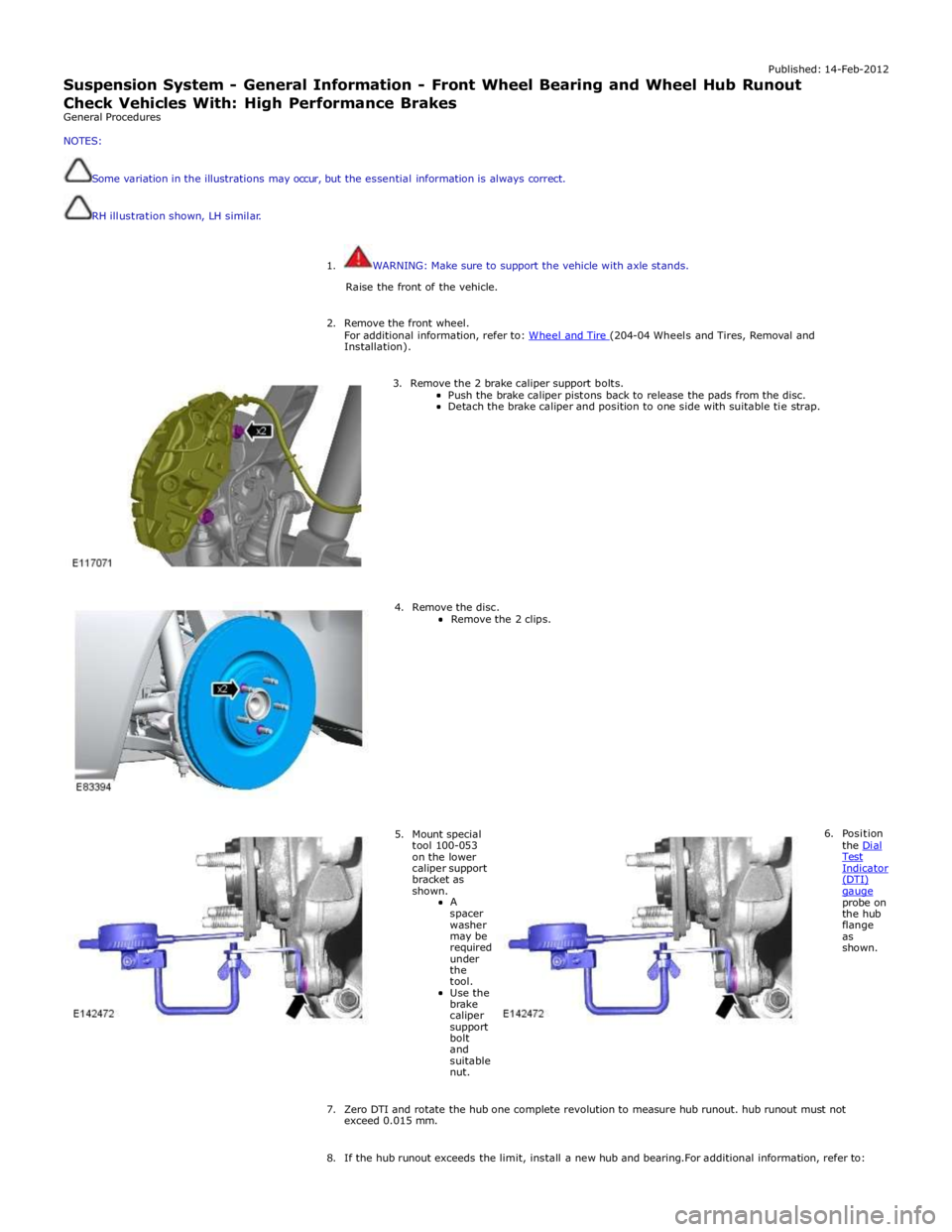
3. Remove the 2 brake caliper support bolts.
Push the brake caliper pistons back to release the pads from the disc. Detach the brake caliper and position to one side with suitable tie strap.
4. Remove the disc.
Remove the 2 clips.
5. Mount special tool 100-053 on the lower caliper support bracket as shown.
A
spacer washer may be required under the tool.
Use the brake caliper support bolt and suitable nut. 6. Position
the Dial Test Indicator (DTI) gauge probe on the hub flange as shown.
7. Zero DTI and rotate the hub one complete revolution to measure hub runout. hub runout must not exceed 0.015 mm.
8. If the hub runout exceeds the limit, install a new hub and bearing.For additional information, refer to:
Page 325 of 3039
Front Wheel Bearing and Wheel Hub - TDV6 3.0L Diesel /V8 5.0L Petrol/V8 S/C 5.0L Petrol (Removal and Installation).
9. If the hub runout is within the limit install the removed components.
10. tighten the brake caliper bolts to 115 Nm.
Page 326 of 3039
Published:
27-Feb-2012
Suspension System - General Information - Rear Wheel Bearing and Wheel
Hub Ru
nout Check
General Procedures
NOTES:
RH illustra tion shown, LH sim ilar.
Some variat ion i n the illustra tions may o ccur, but the es senti al informa tion is always co rrect.
It is recommended that the DTI is capable of measurements of 0.005 mm.
1. WARNING: Make sure to support the vehicle with axle stands.
Raise the rear of the vehicle.
2. Remove the rear wheel.
For additional information, refer to: Wheel and Tire (204-04 Wheels and Tires, Removal and Installation).
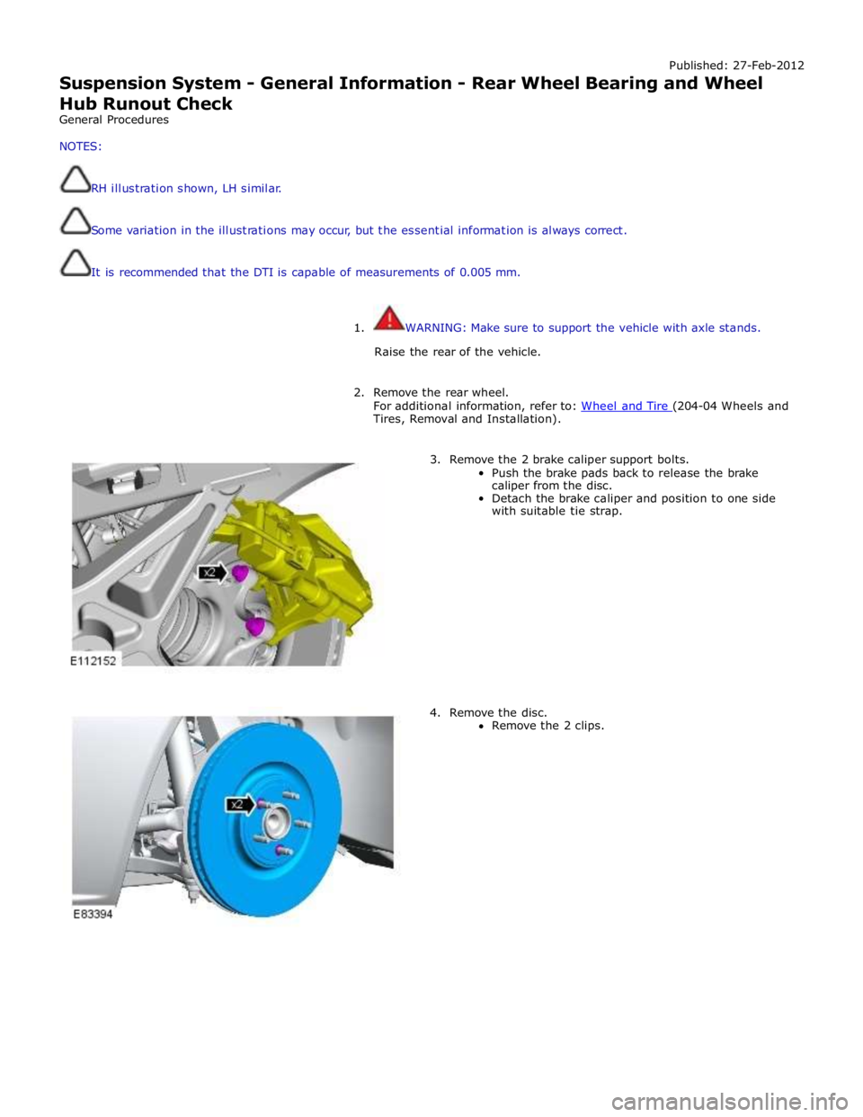
3. Remove the 2 brake caliper support bolts.
Push the brake pads back to release the brake
caliper from the disc.
Detach the brake caliper and position to one side
with suitable tie strap.
4. Remove the disc.
Remove the 2 clips.
Page 327 of 3039
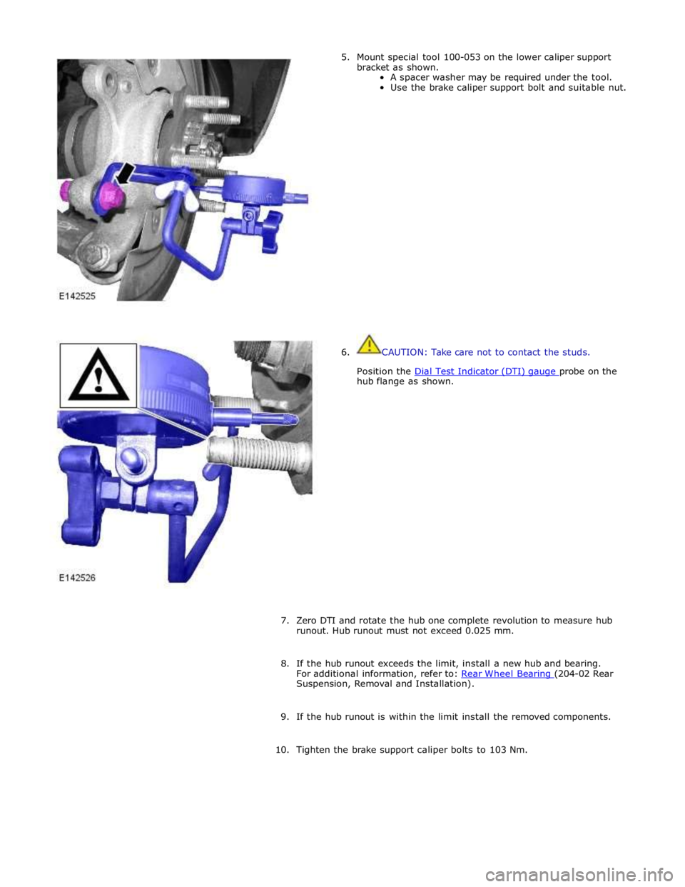
hub flange as shown.
7. Zero DTI and rotate the hub one complete revolution to measure hub
runout. Hub runout must not exceed 0.025 mm.
8. If the hub runout exceeds the limit, install a new hub and bearing.
For additional information, refer to: Rear Wheel Bearing (204-02 Rear Suspension, Removal and Installation).
9. If the hub runout is within the limit install the removed components.
10. Tighten the brake support caliper bolts to 103 Nm.
Page 328 of 3039

Steering gear to subframe retaining bolts 100 74 - Toe link ball joint to wheel knuckle retaining nut 133 98 - Stabilizer bar link to stabilizer bar retaining nut 43 32 - Stabilizer bar link to lower arm retaining nut and bolt 70 52 - Stabilizer bar clamp to subframe retaining bolts 55 41 - Rear lower arm to wheel knuckle ball joint retaining nut 75 55 - Rear lower arm to subframe retaining nut and bolt 175 129 - Front lower arm to subframe retaining nut and bolt 175 129 - Front lower arm to rear lower arm retaining nut and bolt
Stage 1 - 60 Stage 2 - 135 degrees Stage 1 - 44 Stage 2 - 135 degrees - Upper arm ball joint to wheel knuckle retaining nut 90 66 - Upper arm to body retaining nuts and bolts 47 35 - Shock absorber and spring assembly upper mounting to body retaining nuts 28 20 - Shock absorber and spring assembly to lower arm retaining nut and
bolt 175 129 - Shock absorber and spring assembly upper mounting retaining nut (without adaptive damping) 50 37 - Shock absorber and spring assembly upper mounting retaining nut (with adaptive damping) 27 20 - Wheel hub and bearing assembly to wheel knuckle retaining bolt 90 66 - Wheel and tire to wheel hub retaining nuts 125 92 -