hub JAGUAR XFR 2010 1.G Owner's Manual
[x] Cancel search | Manufacturer: JAGUAR, Model Year: 2010, Model line: XFR, Model: JAGUAR XFR 2010 1.GPages: 3039, PDF Size: 58.49 MB
Page 394 of 3039
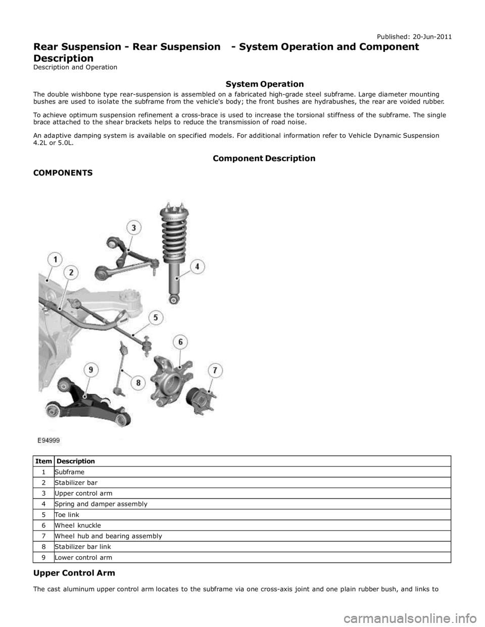
1 Subframe 2 Stabilizer bar 3 Upper control arm 4 Spring and damper assembly 5 Toe link 6 Wheel knuckle 7 Wheel hub and bearing assembly 8 Stabilizer bar link 9 Lower control arm Upper Control Arm
The cast aluminum upper control arm locates to the subframe via one cross-axis joint and one plain rubber bush, and links to
Page 395 of 3039

the aluminum wheel knuckle via an integral ball-joint.
Lower Control Arm
The aluminum lower arm locates to the subframe via one cross-axis joint and one plain rubber bush, and to the wheel knuckle
via a second plain rubber bush.
The rear of the control arm has mounting points for the damper and the stabilizer link.
Toe-Link
The toe-link is located between the wheel knuckle and brackets on the subframe.
The toe-link comprises an inner rod with integral axial ball joint. The inner ball joint has a threaded spigot which locates in a
bracket on the subframe and is secured with a locknut. The rod has an internal thread which accepts the outer rod.
The outer rod has a cross-axis joint at its outer end which is located in a clevis on the wheel knuckle, and is secured with a
bolt and locknut.
The length of the toe-link can be adjusted by rotating the inner rod. This allows for adjustment of the toe angle for the rear
wheel. Once set the inner rod can be locked in position by tightening a locknut on the outer rod against the inner rod.
Wheel Knuckle
The cast aluminum wheel knuckle attaches to:
the upper control arm via a ball-joint located in the arm,
the lower control arm via a plain rubber bush located in the arm,
the toe-link via a cross-axis joint located in the toe link.
The wheel knuckle also provides the mounting locations for the:
wheel hub assembly,
wheel bearing,
wheel speed sensor,
brake caliper,
and disc shield.
Stabilizer Bar
The solid construction stabilizer bar and bushes have been designed to provide particular characteristics in maintaining roll
rates, specifically in primary ride comfort. There are six derivatives of rear stabilizer bar, with different diameters, to support
the various powertrains:
V6 gasoline - 12.7 mm solid bar
V8 4.2L and 5.0L gasoline - 13.6 mm solid bar
V6 2.7L diesel -14.5 mm solid bar
V6 3.0L diesel - 14.5 mm solid bar
V6 3.0L diesel with Adaptive Damping – 16mm tubular
V8 4.2L gasoline supercharged – 16mm tubular
V8 5.0L gasoline supercharged
- SV8 - 17mm tubular
- XFR - 18mm tubular
The stabilizer bar is attached to the top of the subframe with two bushes and mounting brackets. The stabilizer bar has
crimped, 'anti-shuffle' collars pressed in position on the inside edges of the bushes. The collars prevent sideways movement of
the stabilizer bar.
Each end of the stabilizer bar curves rearward to attach to a ball joint on each stabilizer link. Each link is attached via a
second ball joint to a cast bracket on the lower control arm. The links allow the stabilizer bar to move with the wheel travel
providing maximum effectiveness.
Spring and Damper Assembly
The spring and damper assembly are attached to cast brackets on the lower control arms and to the vehicle body by four studs
secured by locking nuts. Dependant on vehicle model there are three types of coil spring and damper available:
a standard oil passive damper (All models except supercharged),
an adaptive damper, also known as Computer Active Technology Suspension (CATS) on 4.2L supercharged vehicles up to
2010MY, For additional information refer to Vehicle Dynamic Suspension 4.2L.
a continuously variable adaptive damper, also known as Adaptive Dynamics System on 5.0L supercharged vehicles from
2010MY. For additional information refer to Vehicle Dynamic Suspension 5.0L.
The dampers are a monotube design with a spring located by a circlip onto the damper tube. The lower end of the damper has
a spherical joint which locates in the lower control arm and is secured with a bolt.
The damper piston is connected to a damper rod which is sealed at its exit point from the damper body. The threaded outer
end of the damper rod locates through a hole in the top mount. A self locking nut secures the top mount to the damper rod.
The damper rod on the adaptive damper has an electrical connector on the outer end of the damper rod. www.JagDocs.com
Page 400 of 3039
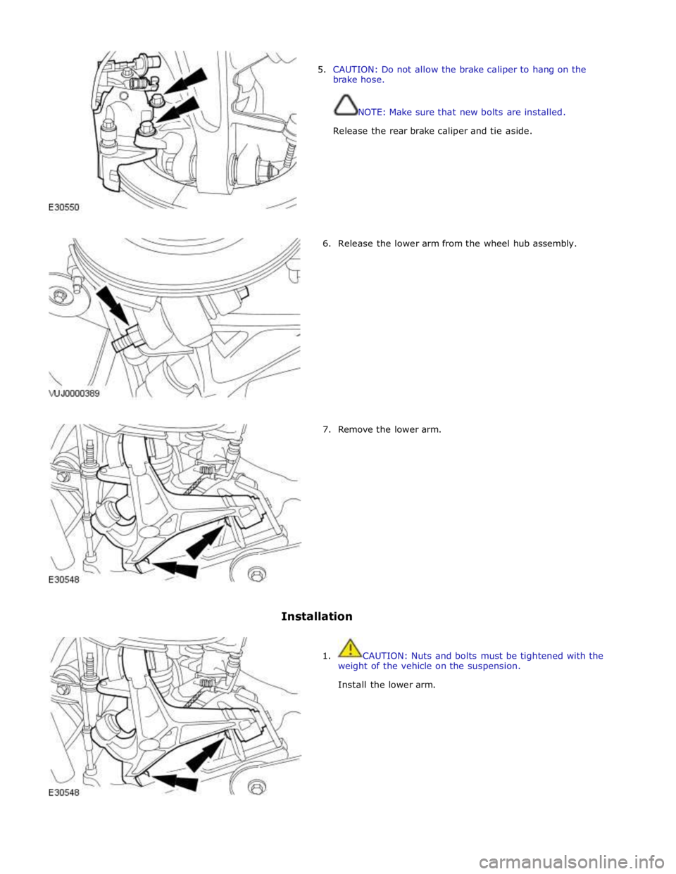
5. CAUTION: Do not allow the brake caliper to hang on the
brake hose.
NOTE: Make sure that new bolts are installed.
Release the rear brake caliper and tie aside.
6. Release the lower arm from the wheel hub assembly.
7. Remove the lower arm.
Installation
1. CAUTION: Nuts and bolts must be tightened with the
weight of the vehicle on the suspension.
Install the lower arm.
Page 401 of 3039
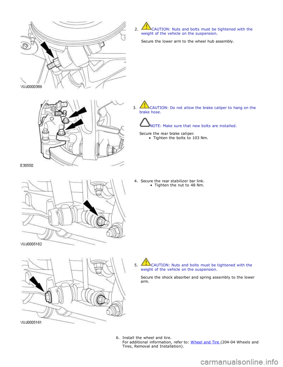
2. CAUTION: Nuts and bolts must be tightened with the
weight of the vehicle on the suspension.
Secure the lower arm to the wheel hub assembly.
3. CAUTION: Do not allow the brake caliper to hang on the
brake hose.
NOTE: Make sure that new bolts are installed.
Secure the rear brake caliper.
Tighten the bolts to 103 Nm.
4. Secure the rear stabilizer bar link.
Tighten the nut to 48 Nm.
5. CAUTION: Nuts and bolts must be tightened with the
weight of the vehicle on the suspension.
Secure the shock absorber and spring assembly to the lower
arm.
6. Install the wheel and tire.
For additional information, refer to: W heel and Tire (204-04 Wheels and Tires, Removal and Installation).
Page 422 of 3039
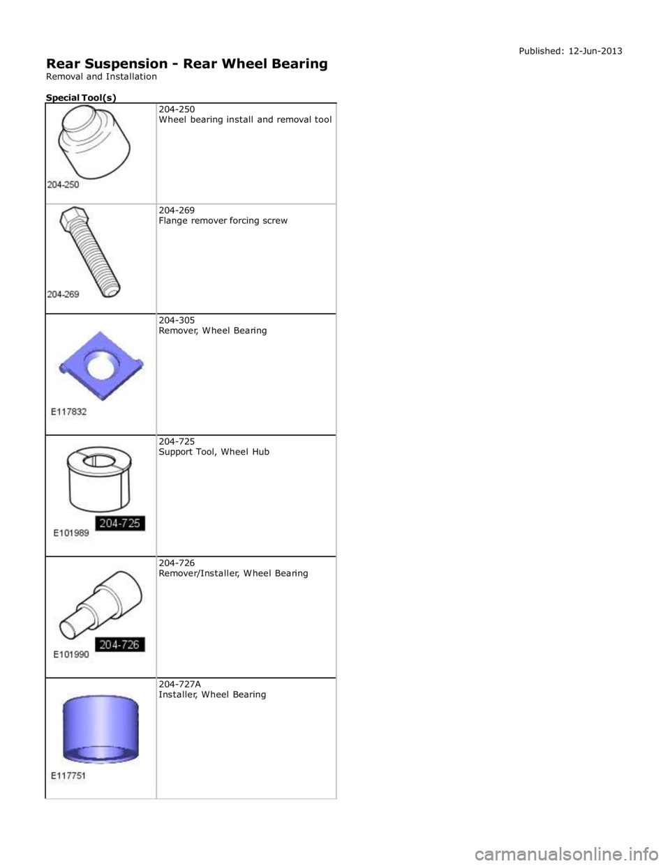
204-269
Flange remover forcing screw
204-305
Remover, Wheel Bearing
204-725
Support Tool, Wheel Hub
204-726
Remover/Installer, Wheel Bearing
204-727A
Installer, Wheel Bearing
Page 423 of 3039
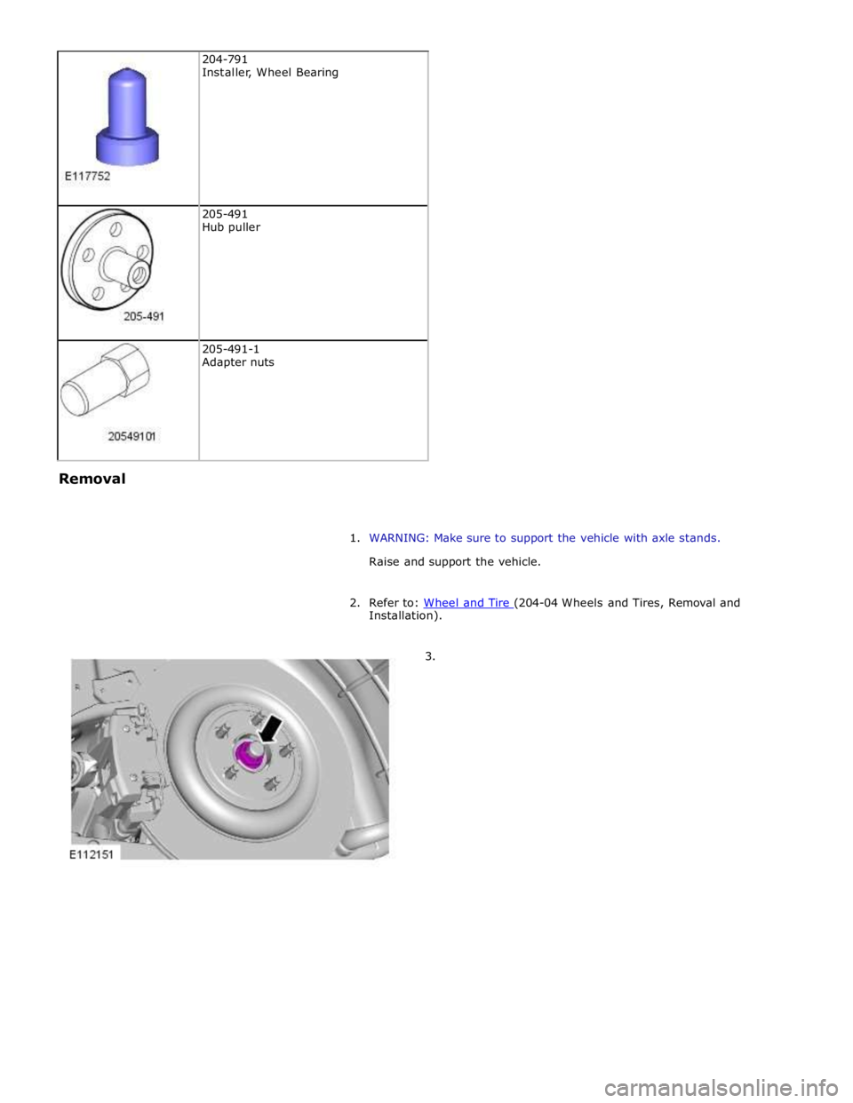
205-491
Hub puller
205-491-1
Adapter nuts Removal
1. WARNING: Make sure to support the vehicle with axle stands.
Raise and support the vehicle.
2. Refer to: Wheel and Tire (204-04 Wheels and Tires, Removal and Installation).
3.
Page 425 of 3039
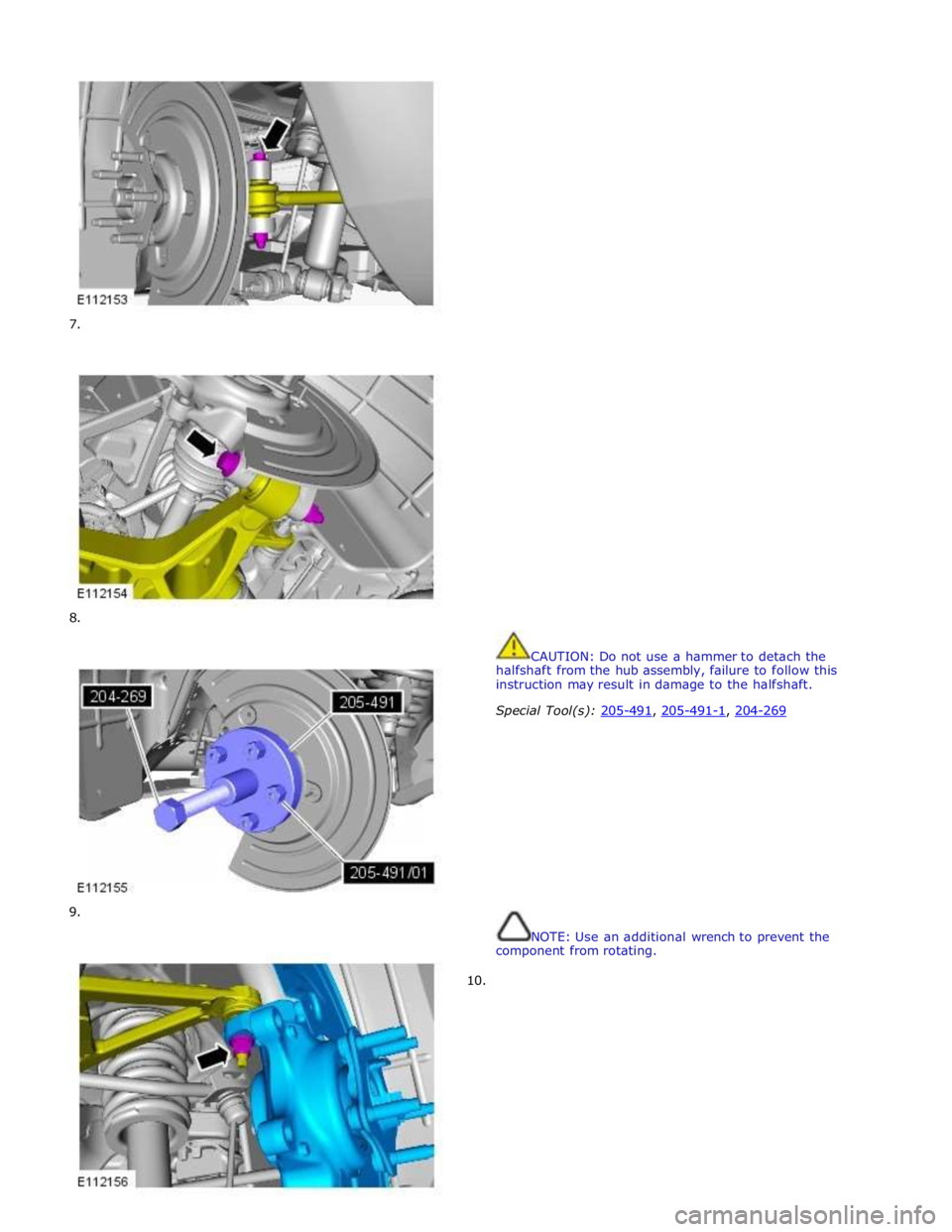
7.
8.
9.
10.
CAUTION: Do not use a hammer to detach the
halfshaft from the hub assembly, failure to follow this
instruction may result in damage to the halfshaft.
Special Tool(s): 205-491, 205-491-1, 204-269
NOTE: Use an additional wrench to prevent the
component from rotating.
Page 427 of 3039
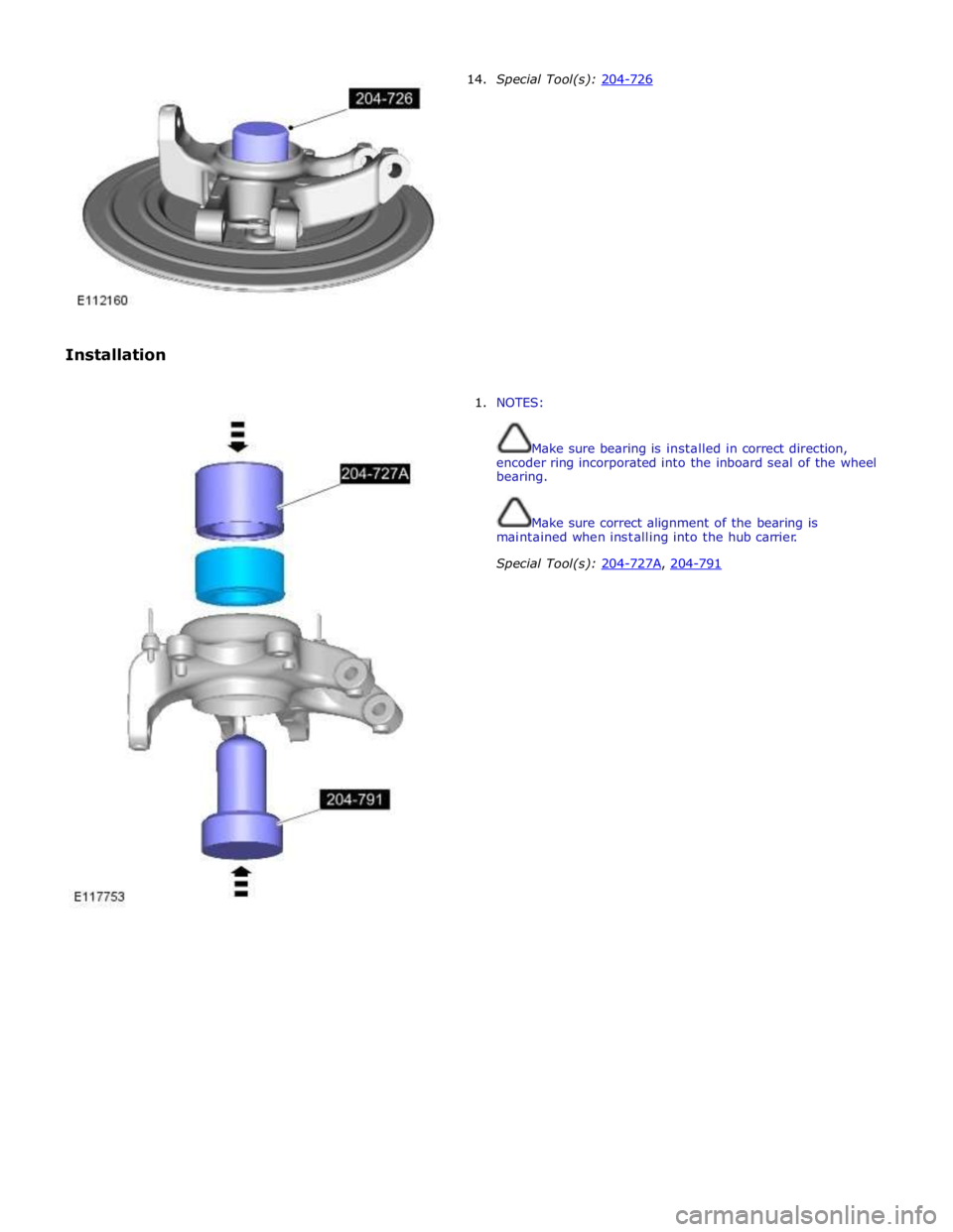
Installation 14. Special Tool(s): 204-726
1. NOTES:
Make sure bearing is installed in correct direction,
encoder ring incorporated into the inboard seal of the wheel
bearing.
Make sure correct alignment of the bearing is
maintained when installing into the hub carrier.
Special Tool(s): 204-727A, 204-791
Page 428 of 3039
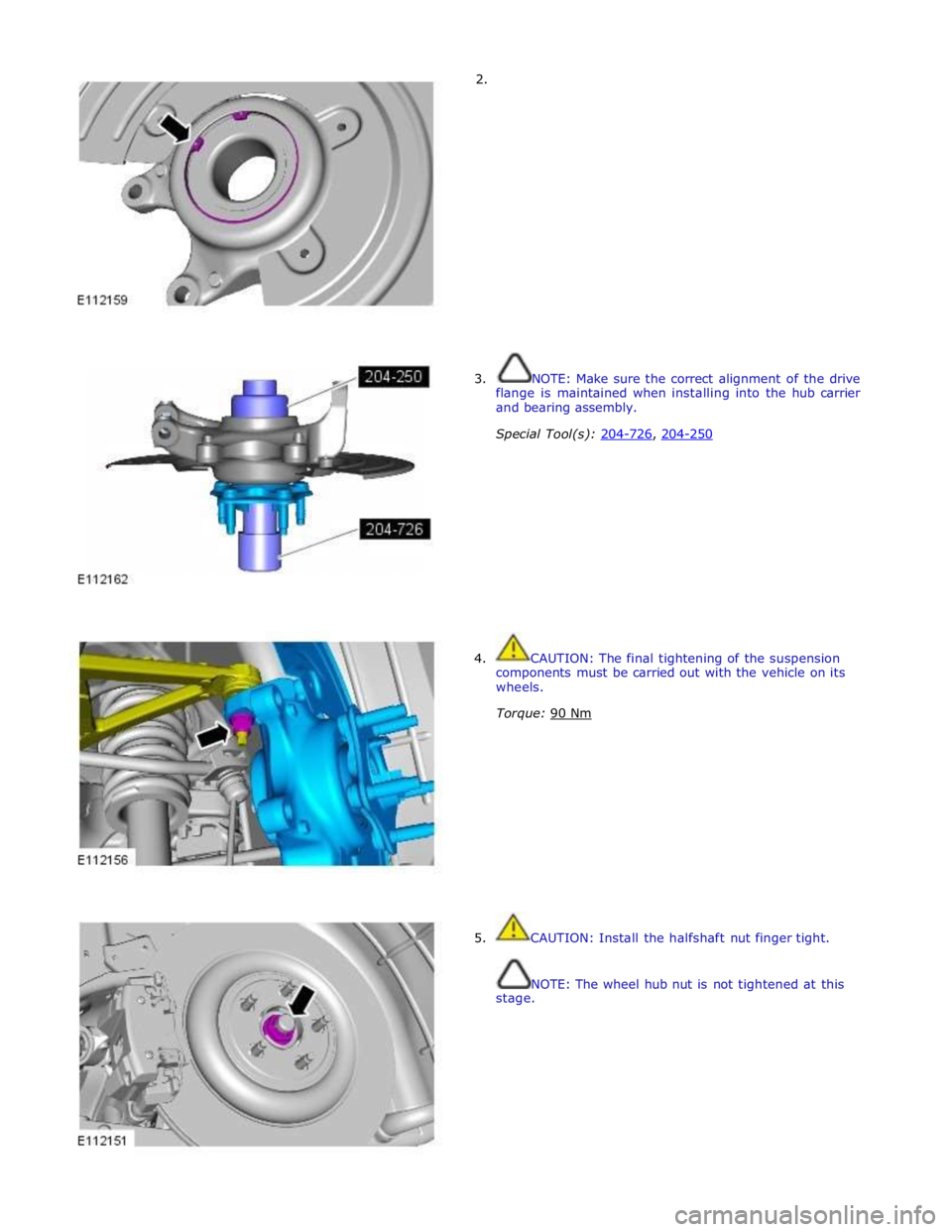
2.
3. NOTE: Make sure the correct alignment of the drive
flange is maintained when installing into the hub carrier
and bearing assembly.
Special Tool(s): 204-726, 204-250
4. CAUTION: The final tightening of the suspension
components must be carried out with the vehicle on its
wheels.
Torque: 90 Nm
5. CAUTION: Install the halfshaft nut finger tight.
NOTE: The wheel hub nut is not tightened at this
stage.
Page 478 of 3039
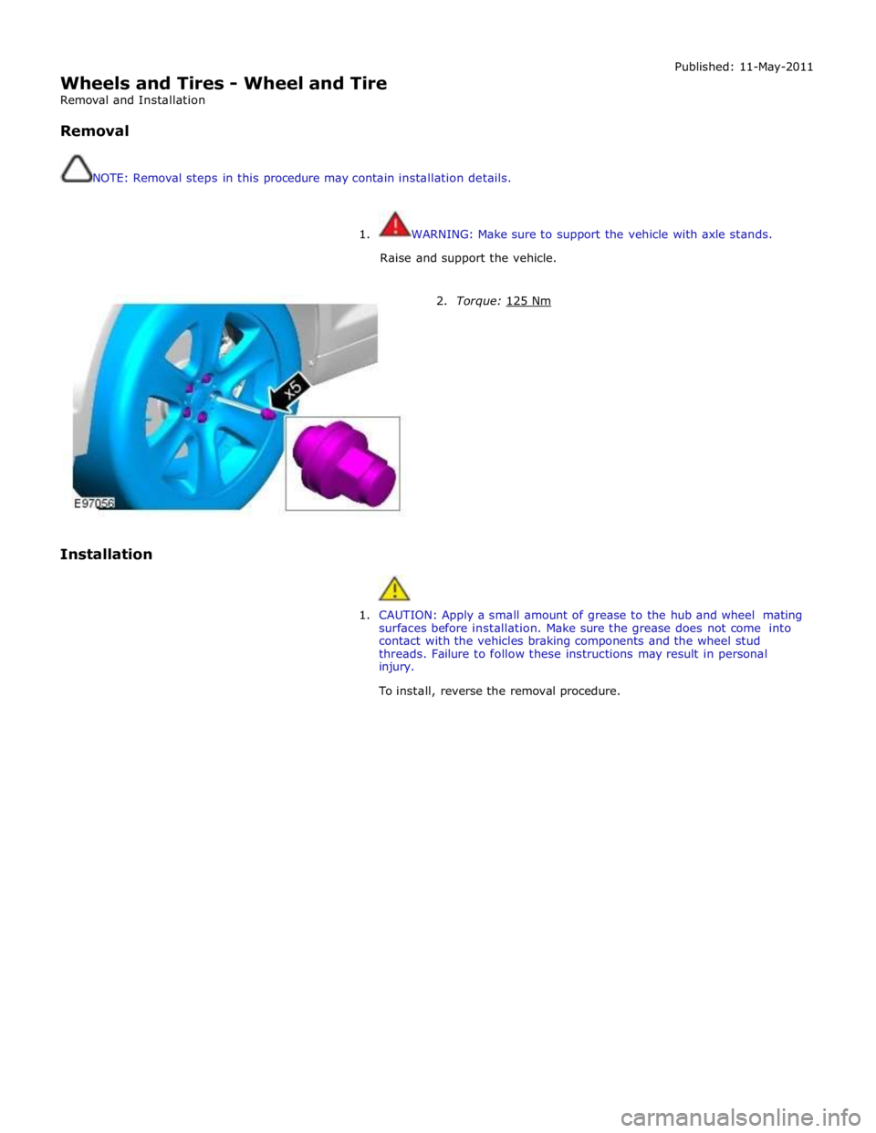
Wheels and Tires - Wheel and Tire
Removal and Installation
Removal
NOTE: Removal steps in this procedure may contain installation details. Published: 11-May-2011
1. WARNING: Make sure to support the vehicle with axle stands.
Raise and support the vehicle.
Installation
2. Torque: 125 Nm
1. CAUTION: Apply a small amount of grease to the hub and wheel mating
surfaces before installation. Make sure the grease does not come into
contact with the vehicles braking components and the wheel stud
threads. Failure to follow these instructions may result in personal
injury.
To install, reverse the removal procedure.