hub JAGUAR XFR 2010 1.G Owner's Guide
[x] Cancel search | Manufacturer: JAGUAR, Model Year: 2010, Model line: XFR, Model: JAGUAR XFR 2010 1.GPages: 3039, PDF Size: 58.49 MB
Page 499 of 3039
Driveline System - General Information - Driveline System
Diagnosis and Testing
Principle of Operation Published: 11-May-2011
For a detailed description of driveline operation, refer to the relevant Description and Operation section in the workshop
manual. REFER to:
Driveshaft (205-01 Driveshaft, Description and Operation), Driveshaft (205-01 Driveshaft, Description and Operation), Driveshaft (205-01 Driveshaft, Description and Operation), Rear Drive Axle and Differential (205-02, Description and Operation),
Rear Drive Axle and Differential (205-02, Description and Operation),
Rear Drive Axle and Differential (205-02, Description and Operation),
Rear Drive Halfshafts (205-05 Rear Drive Halfshafts, Description and Operation), Rear Drive Halfshafts (205-05 Rear Drive Halfshafts, Description and Operation), Rear Drive Halfshafts (205-05 Rear Drive Halfshafts, Description and Operation).
Inspection and Verification
CAUTION: Only serviceable items can be renewed or adjusted. Failure to follow this instruction may result in the warranty
of the component being rejected.
Certain driveline trouble symptoms are also common to the engine, transmission, wheel bearings, tires, and other parts of the
vehicle. For this reason, make sure that the cause of the trouble is in the driveline before adjusting, repairing, or installing any
new components. For additional information, refer to Workshop Manual section 100-04 Noise, Vibration and Harshness.
1. Verify the customer concern by carrying out a road test of the vehicle.
2. Visually inspect for obvious signs of mechanical damage and system integrity.
3. If an obvious cause for an observed or reported concern is found, correct the cause (if possible) before proceeding to
the next step.
4. If the concern is not visually evident, verify the symptom and refer to the Symptom Chart.
Identify the Condition
Gear Howl and Whine
Howling or whining of the ring gear and pinion is due to an incorrect gear pattern, gear damage or incorrect bearing preload.
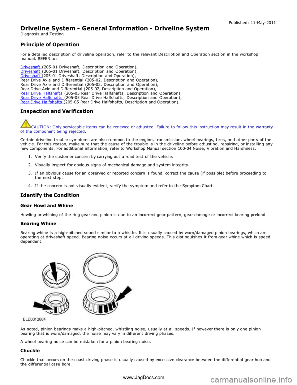
Bearing Whine
Bearing whine is a high-pitched sound similar to a whistle. It is usually caused by worn/damaged pinion bearings, which are
operating at driveshaft speed. Bearing noise occurs at all driving speeds. This distinguishes it from gear whine which is speed
dependent.
As noted, pinion bearings make a high-pitched, whistling noise, usually at all speeds. If however there is only one pinion
bearing that is worn/damaged, the noise may vary in different driving phases.
A wheel bearing noise can be mistaken for a pinion bearing noise.
Chuckle
Chuckle that occurs on the coast driving phase is usually caused by excessive clearance between the differential gear hub and
the differential case bore. www.JagDocs.com
Page 563 of 3039
Published: 11-May-2011
Rear Drive Halfshafts - Rear Drive Halfshafts - System Operation and
Component Description
Description and Operation
System Operation
Rear Drive Halfshafts Component Description
The solid-steel halfshafts are of unequal length, with each halfshaft comprising inner and outer CV (constant velocity) joints.
The CV joints are the 'ball and socket' type packed with grease and protected by gaiters.
The outer CV joint is an interference fit into the wheel hub and secured by a locking nut. The inner CV joint is a slide fit and is
retained in the differential with a spring clip.
www.JagDocs.com
Page 565 of 3039
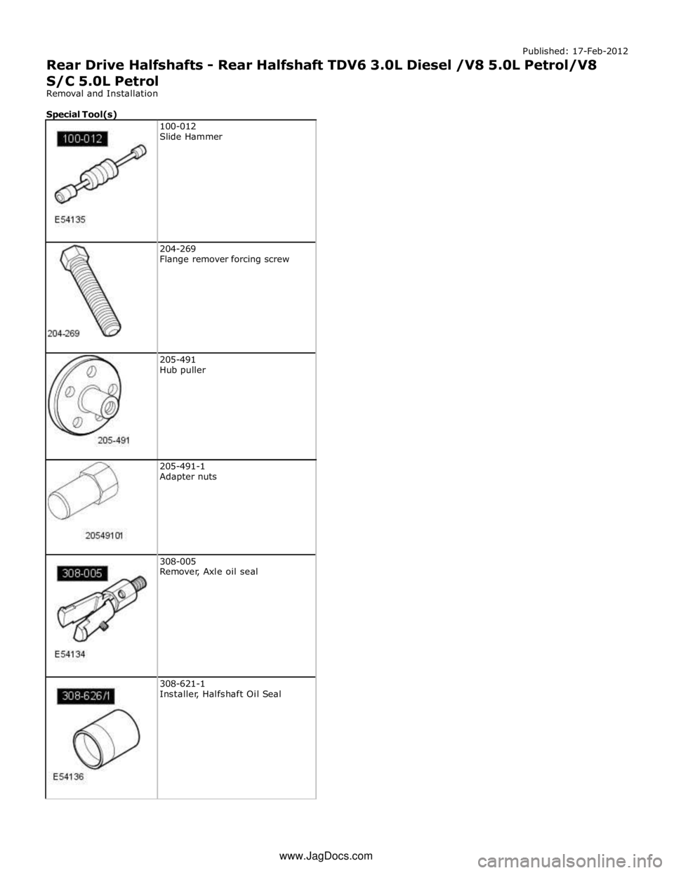
204-269
Flange remover forcing screw
205-491
Hub puller
205-491-1
Adapter nuts
308-005
Remover, Axle oil seal
308-621-1
Installer, Halfshaft Oil Seal www.JagDocs.com
Page 568 of 3039
8.
9.
10.
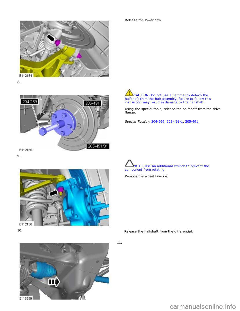
11. Release the lower arm.
CAUTION: Do not use a hammer to detach the
halfshaft from the hub assembly, failure to follow this
instruction may result in damage to the halfshaft.
Using the special tools, release the halfshaft from the drive
flange.
Special Tool(s): 204-269, 205-491-1, 205-491
NOTE: Use an additional wrench to prevent the
component from rotating.
Remove the wheel knuckle.
Release the halfshaft from the differential.
Page 581 of 3039
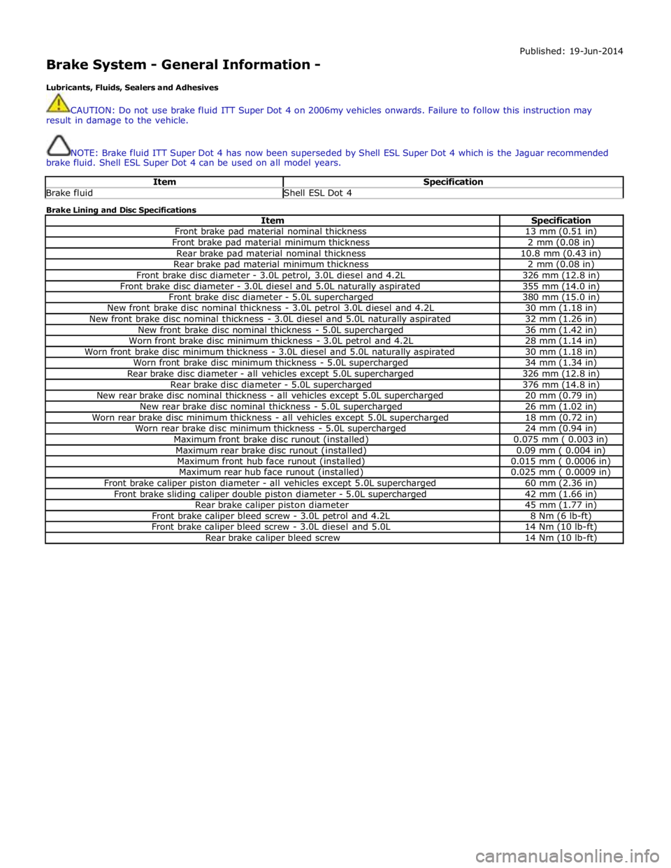
Brake System - General Information -
Lubricants, Fluids, Sealers and Adhesives Published: 19-Jun-2014
CAUTION: Do not use brake fluid ITT Super Dot 4 on 2006my vehicles onwards. Failure to follow this instruction may
result in damage to the vehicle.
NOTE: Brake fluid ITT Super Dot 4 has now been superseded by Shell ESL Super Dot 4 which is the Jaguar recommended
brake fluid. Shell ESL Super Dot 4 can be used on all model years.
Item Specification Brake fluid Shell ESL Dot 4 Brake Lining and Disc Specifications
Item Specification Front brake pad material nominal thickness 13 mm (0.51 in) Front brake pad material minimum thickness 2 mm (0.08 in) Rear brake pad material nominal thickness 10.8 mm (0.43 in) Rear brake pad material minimum thickness 2 mm (0.08 in) Front brake disc diameter - 3.0L petrol, 3.0L diesel and 4.2L 326 mm (12.8 in) Front brake disc diameter - 3.0L diesel and 5.0L naturally aspirated 355 mm (14.0 in) Front brake disc diameter - 5.0L supercharged 380 mm (15.0 in) New front brake disc nominal thickness - 3.0L petrol 3.0L diesel and 4.2L 30 mm (1.18 in) New front brake disc nominal thickness - 3.0L diesel and 5.0L naturally aspirated 32 mm (1.26 in) New front brake disc nominal thickness - 5.0L supercharged 36 mm (1.42 in) Worn front brake disc minimum thickness - 3.0L petrol and 4.2L 28 mm (1.14 in) Worn front brake disc minimum thickness - 3.0L diesel and 5.0L naturally aspirated 30 mm (1.18 in) Worn front brake disc minimum thickness - 5.0L supercharged 34 mm (1.34 in) Rear brake disc diameter - all vehicles except 5.0L supercharged 326 mm (12.8 in) Rear brake disc diameter - 5.0L supercharged 376 mm (14.8 in) New rear brake disc nominal thickness - all vehicles except 5.0L supercharged 20 mm (0.79 in) New rear brake disc nominal thickness - 5.0L supercharged 26 mm (1.02 in) Worn rear brake disc minimum thickness - all vehicles except 5.0L supercharged 18 mm (0.72 in) Worn rear brake disc minimum thickness - 5.0L supercharged 24 mm (0.94 in) Maximum front brake disc runout (installed) 0.075 mm ( 0.003 in) Maximum rear brake disc runout (installed) 0.09 mm ( 0.004 in) Maximum front hub face runout (installed) 0.015 mm ( 0.0006 in) Maximum rear hub face runout (installed) 0.025 mm ( 0.0009 in) Front brake caliper piston diameter - all vehicles except 5.0L supercharged 60 mm (2.36 in) Front brake sliding caliper double piston diameter - 5.0L supercharged 42 mm (1.66 in) Rear brake caliper piston diameter 45 mm (1.77 in) Front brake caliper bleed screw - 3.0L petrol and 4.2L 8 Nm (6 lb-ft) Front brake caliper bleed screw - 3.0L diesel and 5.0L 14 Nm (10 lb-ft) Rear brake caliper bleed screw 14 Nm (10 lb-ft)
Page 583 of 3039
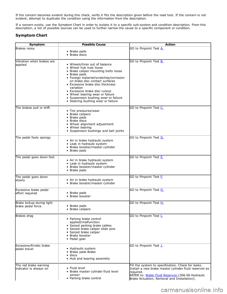
If the concern becomes evident during this check, verify it fits the description given before the road test. If the concern is not
evident, attempt to duplicate the condition using the information from the description.
If a concern exists, use the Symptom Chart in order to isolate it to a specific sub-system and condition description. From this
description, a list of possible sources can be used to further narrow the cause to a specific component or condition.
Symptom Chart
Symptom Possible Cause Action Brakes noisy
Brake pads
Brake discs GO to Pinpoint Test A. Vibration when brakes are
applied
Wheels/tires out of balance
Wheel hub nuts loose
Brake caliper mounting bolts loose
Brake pads
Foreign material/scratches/corrosion
on brake disc contact surfaces
Excessive brake disc thickness
variation
Excessive brake disc runout
Wheel bearing wear or failure
Suspension bushing wear or failure
Steering bushing wear or failure GO to Pinpoint Test B. The brakes pull or drift
Tire pressures/wear
Brake calipers
Brake pads
Brake discs
Wheel alignment adjustment
Wheel bearing
Suspension bushings and ball joints GO to Pinpoint Test C. The pedal feels spongy
Air in brake hydraulic system
Leak in hydraulic system
Brake booster/master cylinder
Brake pads GO to Pinpoint Test D. The pedal goes down fast
Air in brake hydraulic system
Leak in hydraulic system
Brake booster/master cylinder
Brake pads GO to Pinpoint Test E. The pedal goes down
slowly
Air in brake hydraulic system
Brake booster/master cylinder GO to Pinpoint Test F. Excessive brake pedal
effort required
Brake pads
Brake booster GO to Pinpoint Test G. Brake lockup during light
brake pedal force
Brake pads
Brake calipers GO to Pinpoint Test H. Brakes drag
Parking brake control
applied/malfunction
Seized parking brake cables
Seized brake caliper slide pins
Seized brake caliper
Brake booster
Pedal gear GO to Pinpoint Test I. Excessive/Erratic brake
pedal travel
Hydraulic system
Brake pads Brake
discs
Hub and bearing assembly GO to Pinpoint Test J. The red brake warning
indicator is always on
Fluid level
Brake master cylinder fluid level
sensor
Parking brake control Fill the system to specification. Check for leaks.
Install a new brake master cylinder fluid reservoir as
required.
REFER to: Brake Fluid Reservoir (206-06 Hydraulic Brake Actuation, Removal and Installation).
Page 584 of 3039
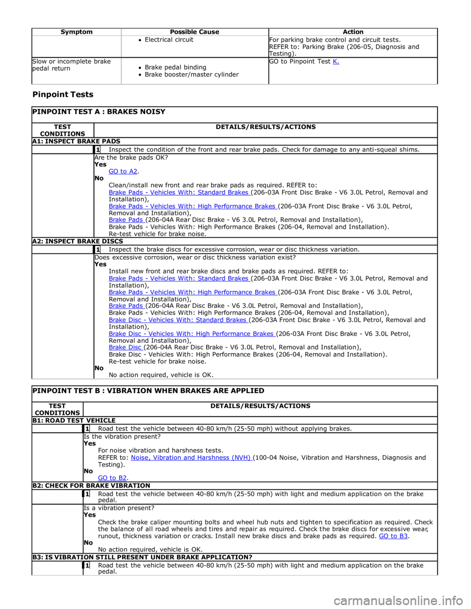
Symptom Possible Cause Action Electrical circuit
For parking brake control and circuit tests.
REFER to: Parking Brake (206-05, Diagnosis and Testing). Slow or incomplete brake
pedal return
Brake pedal binding
Brake booster/master cylinder GO to Pinpoint Test K. Pinpoint Tests
PINPOINT TEST A : BRAKES NOISY TEST
CONDITIONS DETAILS/RESULTS/ACTIONS A1: INSPECT BRAKE PADS 1 Inspect the condition of the front and rear brake pads. Check for damage to any anti-squeal shims. Are the brake pads OK? Yes
GO to A2. No
Clean/install new front and rear brake pads as required. REFER to:
Brake Pads - Vehicles With: Standard Brakes (206-03A Front Disc Brake - V6 3.0L Petrol, Removal and Installation),
Brake Pads - Vehicles With: High Performance Brakes (206-03A Front Disc Brake - V6 3.0L Petrol, Removal and Installation),
Brake Pads (206-04A Rear Disc Brake - V6 3.0L Petrol, Removal and Installation), Brake Pads - Vehicles With: High Performance Brakes (206-04, Removal and Installation).
Re-test vehicle for brake noise. A2: INSPECT BRAKE DISCS 1 Inspect the brake discs for excessive corrosion, wear or disc thickness variation. Does excessive corrosion, wear or disc thickness variation exist? Yes
Install new front and rear brake discs and brake pads as required. REFER to:
Brake Pads - Vehicles With: Standard Brakes (206-03A Front Disc Brake - V6 3.0L Petrol, Removal and Installation),
Brake Pads - Vehicles With: High Performance Brakes (206-03A Front Disc Brake - V6 3.0L Petrol, Removal and Installation),
Brake Pads (206-04A Rear Disc Brake - V6 3.0L Petrol, Removal and Installation), Brake Pads - Vehicles With: High Performance Brakes (206-04, Removal and Installation),
Brake Disc - Vehicles With: Standard Brakes (206-03A Front Disc Brake - V6 3.0L Petrol, Removal and Installation),
Brake Disc - Vehicles With: High Performance Brakes (206-03A Front Disc Brake - V6 3.0L Petrol, Removal and Installation),
Brake Disc (206-04A Rear Disc Brake - V6 3.0L Petrol, Removal and Installation), Brake Disc - Vehicles With: High Performance Brakes (206-04, Removal and Installation).
Re-test vehicle for brake noise.
No
No action required, vehicle is OK.
PINPOINT TEST B : VIBRATION WHEN BRAKES ARE APPLIED TEST
CONDITIONS DETAILS/RESULTS/ACTIONS B1: ROAD TEST VEHICLE 1 Road test the vehicle between 40-80 km/h (25-50 mph) without applying brakes. Is the vibration present?
Yes
For noise vibration and harshness tests.
REFER to: Noise, Vibration and Harshness (NVH) (100-04 Noise, Vibration and Harshness, Diagnosis and Testing).
No
GO to B2. B2: CHECK FOR BRAKE VIBRATION 1 Road test the vehicle between 40-80 km/h (25-50 mph) with light and medium application on the brake pedal. Is a vibration present?
Yes
Check the brake caliper mounting bolts and wheel hub nuts and tighten to specification as required. Check
the balance of all road wheels and tires and repair as required. Check the brake discs for excessive wear,
runout, thickness variation or cracks. Install new brake discs and brake pads as required. GO to B3. No
No action required, vehicle is OK. B3: IS VIBRATION STILL PRESENT UNDER BRAKE APPLICATION? 1 Road test the vehicle between 40-80 km/h (25-50 mph) with light and medium application on the brake pedal.
Page 585 of 3039
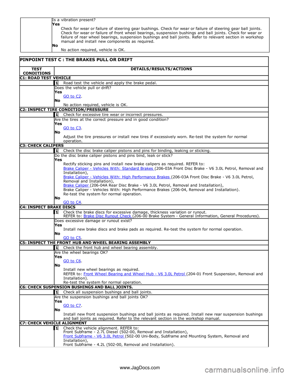
TEST
CONDITIONS DETAILS/RESULTS/ACTIONS C1: ROAD TEST VEHICLE 1 Road test the vehicle and apply the brake pedal. Does the vehicle pull or drift?
Yes
GO to C2. No
No action required, vehicle is OK. C2: INSPECT TIRE CONDITION/PRESSURE 1 Check for excessive tire wear or incorrect pressures. Are the tires at the correct pressure and in good condition?
Yes
GO to C3. No
Adjust the tire pressures or install new tires if excessively worn. Re-test the system for normal operation. C3: CHECK CALIPERS 1 Check the disc brake caliper pistons and pins for binding, leaking or sticking. Do the disc brake caliper pistons and pins bind, leak or stick?
Yes
Rectify sticking pins and install new brake calipers as required. REFER to:
Brake Caliper - Vehicles With: Standard Brakes (206-03A Front Disc Brake - V6 3.0L Petrol, Removal and Installation),
Brake Caliper - Vehicles With: High Performance Brakes (206-03A Front Disc Brake - V6 3.0L Petrol, Removal and Installation),
Brake Caliper (206-04A Rear Disc Brake - V6 3.0L Petrol, Removal and Installation), Brake Caliper - Vehicles With: High Performance Brakes (206-04, Removal and Installation).
Re-test the system for normal operation.
No
GO to C4. C4: INSPECT BRAKE DISCS 1 Check the brake discs for excessive damage, thickness variation or runout. REFER to: Brake Disc Runout Check (206-00 Brake System - General Information, General Procedures). Does excessive damage or runout exist?
Yes
Install new brake discs and brake pads as required. Re-test the system for normal operation.
No
GO to C5. C5: INSPECT THE FRONT HUB AND WHEEL BEARING ASSEMBLY 1 Check the front hub and wheel bearing assembly. Are the wheel bearings OK?
Yes
GO to C6. No
Install new wheel bearings as required.
REFER to: Front Wheel Bearing and Wheel Hub - V6 3.0L Petrol (204-01 Front Suspension, Removal and Installation).
Re-test the system for normal operation. C6: CHECK SUSPENSION BUSHINGS AND BALL JOINTS. 1 Check all suspension bushings and ball joints. Are the suspension bushings and ball joints OK?
Yes
GO to C7. No
Install new front suspension bushings and ball joints as required. Install new rear suspension bushings
and ball joints as required. Refer to the relevant section in the workshop manual. C7: CHECK VEHICLE ALIGNMENT 1 Check the vehicle alignment. REFER to: Front Subframe - 2.7L Diesel (502-00, Removal and Installation),
Front Subframe - V6 3.0L Petrol (502-00 Uni-Body, Subframe and Mounting System, Removal and Installation),
Front Subframe - 4.2L (502-00, Removal and Installation). Is a vibration present?
Yes
Check for wear or failure of steering gear bushings. Check for wear or failure of steering gear ball joints.
Check for wear or failure of front wheel bearings, suspension bushings and ball joints. Check for wear or
failure of rear wheel bearings, suspension bushings and ball joints. Refer to relevant section in workshop
manual and install new components as required.
No
No action required, vehicle is OK.
www.JagDocs.com
Page 589 of 3039
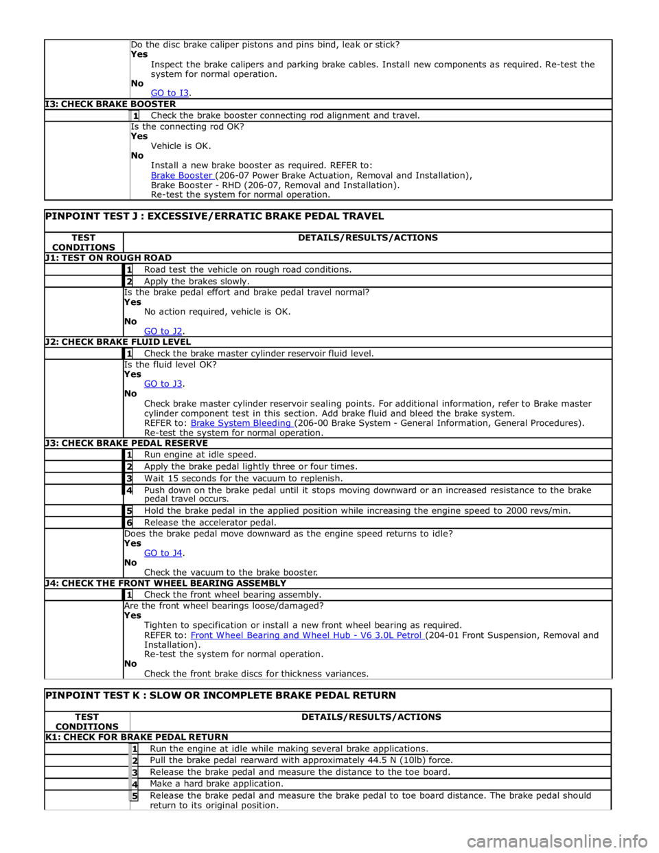
Yes
Inspect the brake calipers and parking brake cables. Install new components as required. Re-test the
system for normal operation.
No
GO to I3. I3: CHECK BRAKE BOOSTER 1 Check the brake booster connecting rod alignment and travel. Is the connecting rod OK? Yes
Vehicle is OK.
No
Install a new brake booster as required. REFER to:
Brake Booster (206-07 Power Brake Actuation, Removal and Installation), Brake Booster - RHD (206-07, Removal and Installation).
Re-test the system for normal operation.
PINPOINT TEST J : EXCESSIVE/ERRATIC BRAKE PEDAL TRAVEL TEST
CONDITIONS DETAILS/RESULTS/ACTIONS J1: TEST ON ROUGH ROAD 1 Road test the vehicle on rough road conditions. 2 Apply the brakes slowly. Is the brake pedal effort and brake pedal travel normal?
Yes
No action required, vehicle is OK.
No
GO to J2. J2: CHECK BRAKE FLUID LEVEL 1 Check the brake master cylinder reservoir fluid level. Is the fluid level OK?
Yes
GO to J3. No
Check brake master cylinder reservoir sealing points. For additional information, refer to Brake master
cylinder component test in this section. Add brake fluid and bleed the brake system.
REFER to: Brake System Bleeding (206-00 Brake System - General Information, General Procedures). Re-test the system for normal operation. J3: CHECK BRAKE PEDAL RESERVE 1 Run engine at idle speed. 2 Apply the brake pedal lightly three or four times. 3 Wait 15 seconds for the vacuum to replenish. 4 Push down on the brake pedal until it stops moving downward or an increased resistance to the brake pedal travel occurs. 5 Hold the brake pedal in the applied position while increasing the engine speed to 2000 revs/min. 6 Release the accelerator pedal. Does the brake pedal move downward as the engine speed returns to idle?
Yes
GO to J4. No
Check the vacuum to the brake booster. J4: CHECK THE FRONT WHEEL BEARING ASSEMBLY 1 Check the front wheel bearing assembly. Are the front wheel bearings loose/damaged?
Yes
Tighten to specification or install a new front wheel bearing as required.
REFER to: Front Wheel Bearing and Wheel Hub - V6 3.0L Petrol (204-01 Front Suspension, Removal and Installation).
Re-test the system for normal operation.
No
Check the front brake discs for thickness variances.
PINPOINT TEST K : SLOW OR INCOMPLETE BRAKE PEDAL RETURN TEST
CONDITIONS DETAILS/RESULTS/ACTIONS K1: CHECK FOR BRAKE PEDAL RETURN 1 Run the engine at idle while making several brake applications. 2 Pull the brake pedal rearward with approximately 44.5 N (10lb) force. 3 Release the brake pedal and measure the distance to the toe board. 4 Make a hard brake application. 5 Release the brake pedal and measure the brake pedal to toe board distance. The brake pedal should return to its original position.
Page 592 of 3039
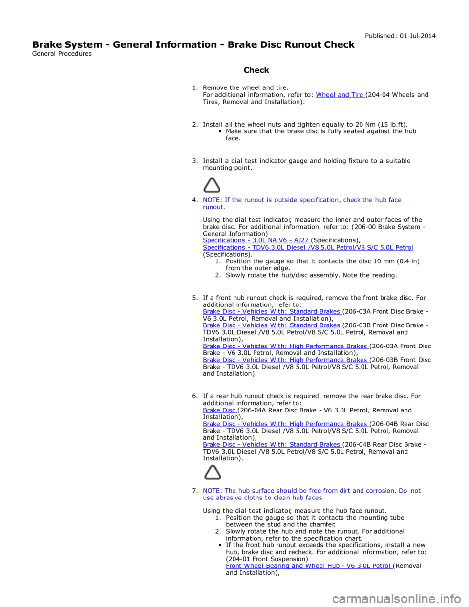
Brake System - General Information - Brake Disc Runout Check
General Procedures
Check Published: 01-Jul-2014
1. Remove the wheel and tire.
For additional information, refer to: Wheel and Tire (204-04 Wheels and Tires, Removal and Installation).
2. Install all the wheel nuts and tighten equally to 20 Nm (15 lb.ft).
Make sure that the brake disc is fully seated against the hub
face.
3. Install a dial test indicator gauge and holding fixture to a suitable
mounting point.
4. NOTE: If the runout is outside specification, check the hub face
runout.
Using the dial test indicator, measure the inner and outer faces of the
brake disc. For additional information, refer to: (206-00 Brake System -
General Information)
Specifications - 3.0L NA V6 - AJ27 (Specifications), Specifications - TDV6 3.0L Diesel /V8 5.0L Petrol/V8 S/C 5.0L Petrol (Specifications).
1. Position the gauge so that it contacts the disc 10 mm (0.4 in)
from the outer edge.
2. Slowly rotate the hub/disc assembly. Note the reading.
5. If a front hub runout check is required, remove the front brake disc. For
additional information, refer to:
Brake Disc - Vehicles With: Standard Brakes (206-03A Front Disc Brake - V6 3.0L Petrol, Removal and Installation),
Brake Disc - Vehicles With: Standard Brakes (206-03B Front Disc Brake - TDV6 3.0L Diesel /V8 5.0L Petrol/V8 S/C 5.0L Petrol, Removal and
Installation),
Brake Disc - Vehicles With: High Performance Brakes (206-03A Front Disc Brake - V6 3.0L Petrol, Removal and Installation),
Brake Disc - Vehicles With: High Performance Brakes (206-03B Front Disc Brake - TDV6 3.0L Diesel /V8 5.0L Petrol/V8 S/C 5.0L Petrol, Removal
and Installation).
6. If a rear hub runout check is required, remove the rear brake disc. For
additional information, refer to:
Brake Disc (206-04A Rear Disc Brake - V6 3.0L Petrol, Removal and Installation),
Brake Disc - Vehicles With: High Performance Brakes (206-04B Rear Disc Brake - TDV6 3.0L Diesel /V8 5.0L Petrol/V8 S/C 5.0L Petrol, Removal
and Installation),
Brake Disc - Vehicles With: Standard Brakes (206-04B Rear Disc Brake - TDV6 3.0L Diesel /V8 5.0L Petrol/V8 S/C 5.0L Petrol, Removal and
Installation).
7. NOTE: The hub surface should be free from dirt and corrosion. Do not
use abrasive cloths to clean hub faces.
Using the dial test indicator, measure the hub face runout.
1. Position the gauge so that it contacts the mounting tube
between the stud and the chamfer.
2. Slowly rotate the hub and note the runout. For additional
information, refer to the specification chart.
If the front hub runout exceeds the specifications, install a new
hub, brake disc and recheck. For additional information, refer to:
(204-01 Front Suspension)
Front Wheel Bearing and Wheel Hub - V6 3.0L Petrol (Removal and Installation),