Interior JAGUAR XFR 2010 1.G Workshop Manual
[x] Cancel search | Manufacturer: JAGUAR, Model Year: 2010, Model line: XFR, Model: JAGUAR XFR 2010 1.GPages: 3039, PDF Size: 58.49 MB
Page 2427 of 3039
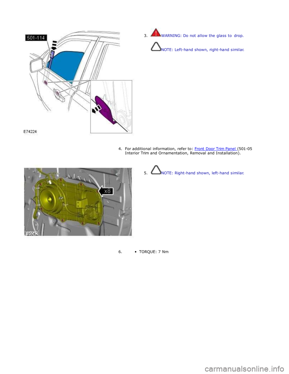
3. WARNING: Do not allow the glass to drop.
NOTE: Left-hand shown, right-hand similar.
4. For additional information, refer to: Front Door Trim Panel (501-05 Interior Trim and Ornamentation, Removal and Installation).
5. NOTE: Right-hand shown, left-hand similar.
6. TORQUE: 7 Nm
Page 2436 of 3039
Glass, Frames and Mechanisms - Rear Window Glass
Removal and Installation
Removal
CAUTIONS:
Always protect paintwork and glass when removing exterior components.
Always protect the interior components when removing body glass. Published: 04-Sep-2013
Lay the glass on felt covered supports. Do not stand on edge as this can cause chips which subsequently develop into
cracks.
NOTE: The following equipment is required: l Cutting wire and handles l Kent knife l Glazing knife l Windshield
replacement kit l Sealant applicator gun l Suction cups l A felt covered table or stand to support glass
1. Refer to: C-Pillar Trim Panel (501-05 Interior Trim and Ornamentation, Removal and Installation).
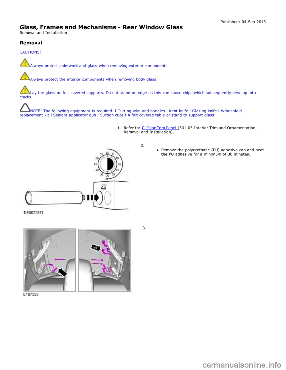
2.
Remove the polyurethane (PU) adhesive cap and heat
the PU adhesive for a minimum of 30 minutes.
3.
Page 2440 of 3039
Glass, Frames and Mechanisms - Windshield Glass
Removal and Installation
Removal
NOTE: Removal steps in this procedure may contain installation details. Published: 04-Sep-2013
1. Refer to: Cowl Vent Screen (501-02 Front End Body Panels, Removal and Installation).
2. Refer to: A-Pillar Trim Panel (501-05 Interior Trim and Ornamentation, Removal and Installation).
3. Refer to: Rain Sensor (501-16 Wipers and Washers, Removal and Installation).
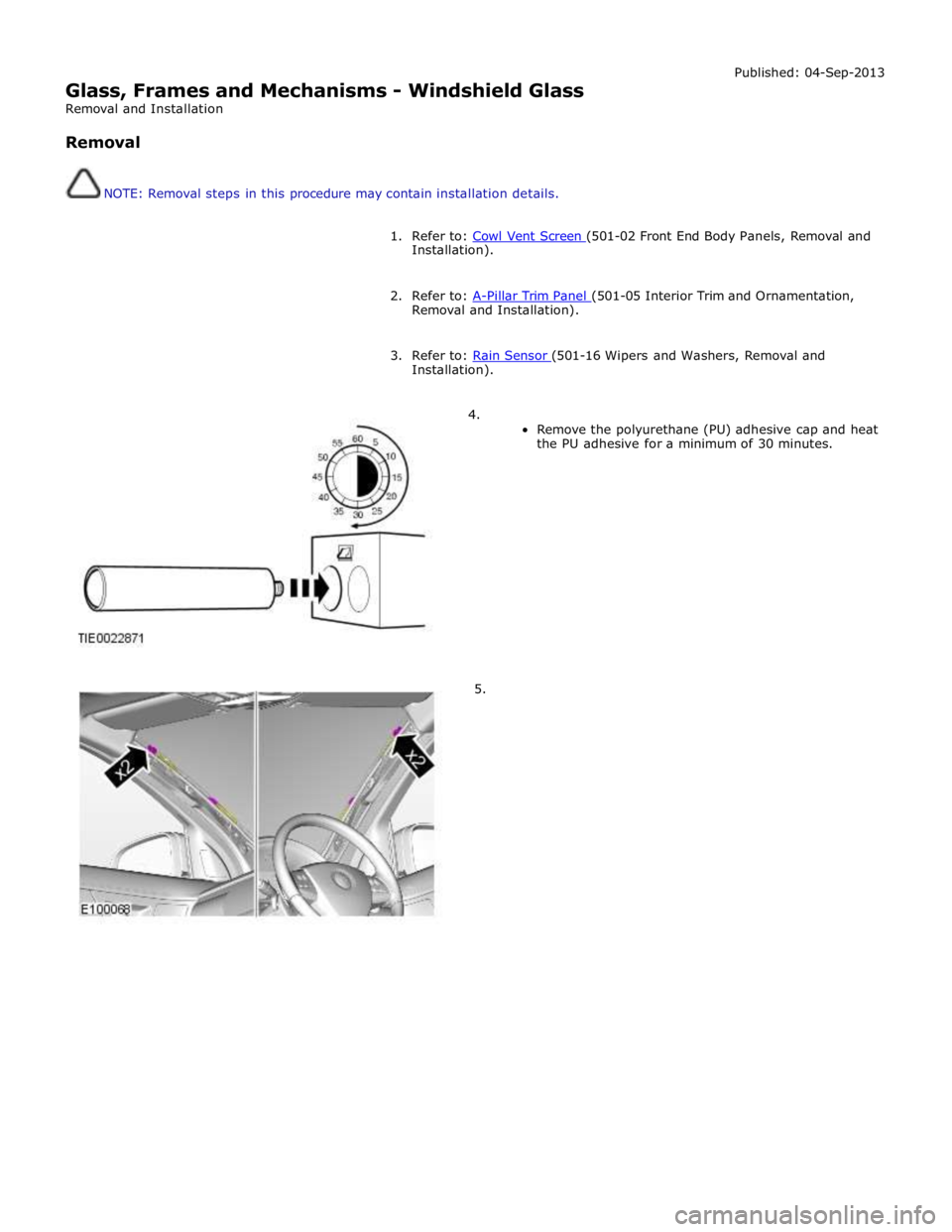
4.
Remove the polyurethane (PU) adhesive cap and heat
the PU adhesive for a minimum of 30 minutes.
5.
Page 2443 of 3039

Installation).
7. Refer to: A-Pillar Trim Panel (501-05 Interior Trim and Ornamentation, Removal and Installation).
8. Refer to: Cowl Vent Screen (501-02 Front End Body Panels, Removal and Installation).
Page 2444 of 3039
Glass, Frames and Mechanisms - Door Window Regulator Motor
Removal and Installation
Removal Published: 11-May-2011
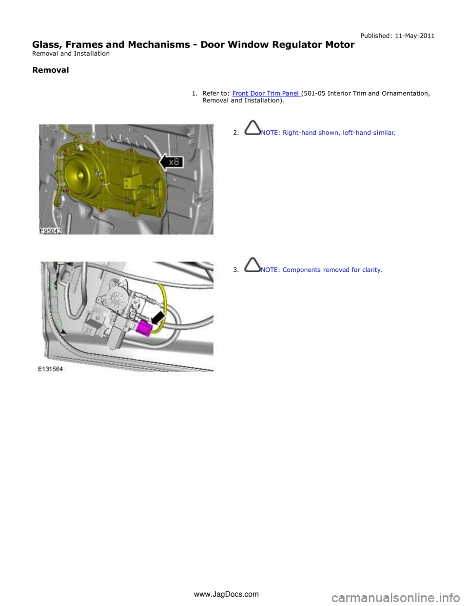
1. Refer to: Front Door Trim Panel (501-05 Interior Trim and Ornamentation, Removal and Installation).
2. NOTE: Right-hand shown, left-hand similar.
3. NOTE: Components removed for clarity. www.JagDocs.com
Page 2447 of 3039
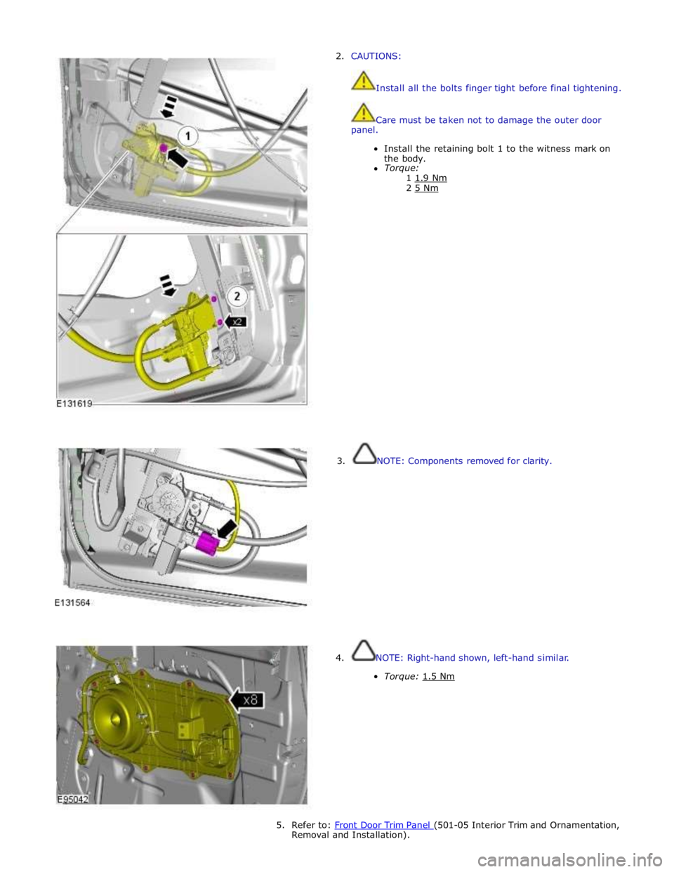
2. CAUTIONS:
Install all the bolts finger tight before final tightening.
Care must be taken not to damage the outer door
panel.
Install the retaining bolt 1 to the witness mark on
the body.
Torque:
1 1.9 Nm 2 5 Nm
3. NOTE: Components removed for clarity.
4. NOTE: Right-hand shown, left-hand similar.
Torque: 1.5 Nm
5. Refer to: Front Door Trim Panel (501-05 Interior Trim and Ornamentation, Removal and Installation).
Page 2470 of 3039
8. Refer to: Floor Console (501-12 Instrument Panel and Console, Removal and Installation).
9. Refer to: Glove Compartment (501-12 Instrument Panel and Console, Removal and Installation).
10. Refer to: Instrument Panel Lower Trim Panel (501-12 Instrument Panel and Console, Removal and Installation).
11. Refer to: A-Pillar Trim Panel (501-05 Interior Trim and Ornamentation, Removal and Installation).
12. Refer to: Cowl Side Trim Panel (501-05 Interior Trim and Ornamentation, Removal and Installation).
13. Refer to: Steering Wheel (211-04 Steering Column, Removal and Installation).
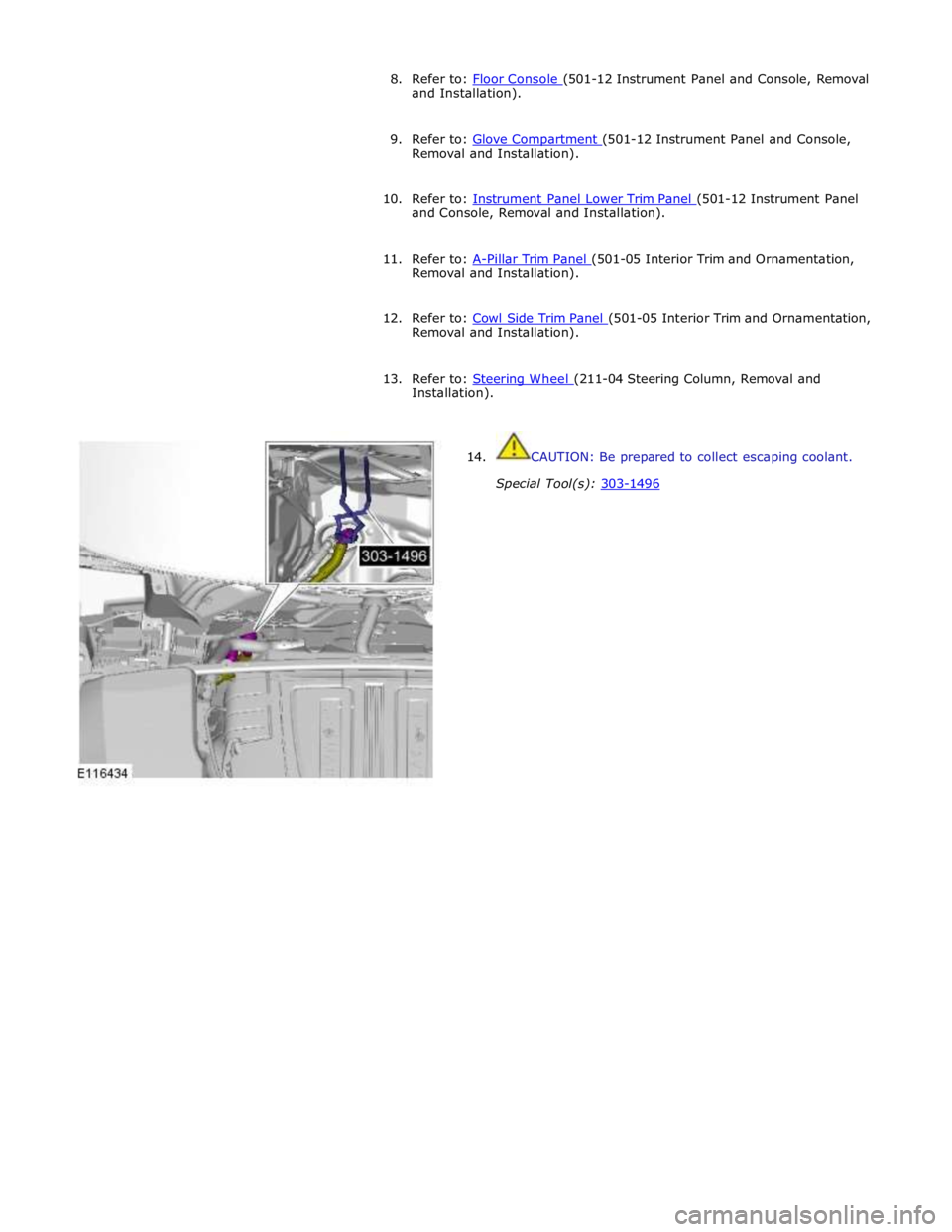
14. CAUTION: Be prepared to collect escaping coolant.
Special Tool(s): 303-1496
Page 2486 of 3039

Front and rear door latch retaining screw 7 - 62 Front and Rear exterior door handle / Door lock captive retaining screw 4 - 36 Front and Rear Exterior Door handle seperate retaining screw 3 - 28 Front and Rear Door striker retaining screw 25 18 - Interior Door handle retaining Screw 1.3 - 11.5 Hood latch Reataining screw 10 8 - Hood Striker Retaining screw 22 17 - Trunk Latch Retaining screw 20 15 - Trunk Striker Retaining screw 22 17 - Trunk Lock Retaining screw 3 - 28
Page 2493 of 3039

Item Description Note: A = Hardwired; N = Medium speed CAN 1 Battery 2 Megafuse (250 A) 3 CJB 4 Radio frequency receiver 5 Keylesss vehicle module 6 Door handle, lock/unlock switch and antenna - front passenger 7 Door latch, fast latch - front passenger 8 Door latch, fast latch - RH rear passenger 9 Door handle, lock/unlock switch and antenna - RH rear passenger 10 Door latch, fast latch - LH rear passenger 11 Door handle, lock/unlock switch and antenna - LH rear passenger 12 Door latch, fast latch - driver door 13 Door handle, lock/unlock switch and antenna - driver door
System Operation
The hinged panels are secured with latches and strikers. A remotely operated central locking system controls the locking and
unlocking of the door and luggage compartment latches. A radio frequency Smart Key allows the vehicle to be locked and
unlocked by pressing the appropriate handset buttons. Two levels of central locking system are available: remote central
locking and an optional passive entry system.
The passive entry and associated passive start system allows the driver to unlock and start the vehicle without using a vehicle
key in a door-lock or ignition switch. The passive entry system is an optional fitment while the passive start system is a
standard fitment on all vehicles. The passive start system is combined with the passive anti-theft immobilization system.
Refer to: Anti-Theft - Passive (419-01B Anti-Theft - Passive, Description and Operation).
Emergency access to the vehicle is provided by two concealed key barrels: one located in the front left-hand door handle and
one located on the underside of the luggage compartment lid finisher. An emergency, removable key blade is fitted into the
Smart Key.
Operation of either key barrel unlocks the vehicle but does not disarm the alarm system. The key barrels in the door and
luggage compartment lid are concealed by a plastic cover which can be removed by inserting the blade of the emergency key
into a slot in the cover.
Locking and unlocking conditions using the emergency key in the door key barrel:
If the alarm is not armed the vehicle can be centrally unlocked.
If the alarm is armed the door only can be opened and the alarm will be triggered.
The vehicle cannot be double locked or the alarm system armed using the emergency key.
The vehicle can be centrally locked and unlocked from inside using the interior handle release levers on the front doors only.
Central locking and unlocking can also be performed using lock and unlock buttons on the vehicle's fascia. The driver can select
locking options, single point entry or drive away locking for example, from a menu available on the touch screen.
Central Locking – Radio Frequency Remote System
The radio frequency central locking system, provides locking and unlocking of the vehicle from inside and outside of the
vehicle. The system is operated using buttons on the Smart Key, which transmits radio frequency signals to the central locking
radio frequency receiver.
The system provides additional security by double-locking the doors from outside the vehicle if the lock button, on the Smart
Key, is pressed twice within 3 seconds; this function is not applicable in North American Specification (NAS) and Japanese
markets.
Additional buttons on the Smart Key provide for the convenience operation of the luggage compartment lid release, headlamp
delay and panic alarm functions. A global open or close feature is also available in certain markets using the lock/unlock
buttons.
Passive Entry
On vehicles fitted with the optional passive entry system, the vehicle can be unlocked without the use of a key blade or
pressing buttons on the Smart Key. The Smart Key operates the passive entry system in addition to the passive start system.
Refer to: Anti-Theft - Passive (419-01B Anti-Theft - Passive, Description and Operation).
The passive entry system is controlled by the keyless vehicle module and five low frequency antennas. One antenna located in
each door handle and one antenna located behind the rear bumper cover.
When a vehicle door handle is pulled to the first five-percent of its travel and the Smart Key is within one meter of the handle;
the Smart Key receives the low-frequency signal transmitted from the keyless vehicle module. The Smart Key responds with a
radio frequency transmission of its authorization code. The radio frequency signal is received by the central locking radio-
frequency receiver and passed to the keyless vehicle module which checks and approves the code as valid. Once the handle is
Page 2494 of 3039

door modules.
Locking of the vehicle is performed by pressing one of the buttons located on each exterior door handle, with the Smart Key
within a one meter range of the vehicle. When the door handle button is pressed, the keyless vehicle module transmits a
low-frequency signal via the low-frequency handle antenna to the Smart Key. The Smart Key transmits a radio frequency signal
which is verified by the keyless vehicle module and allows the doors to be locked or double locked and the alarm system to be
armed.
To double lock the vehicle, the button on the exterior door handle must be pressed twice within three seconds, with the Smart
Key within one meter range of the vehicle.
If a door, engine-compartment lid or the luggage compartment lid is ajar when an attempt to lock the vehicle is made, an error
tone is emitted and no locking action will occur.
Refer to: Anti-Theft - Active (419-01A Anti-Theft - Active, Description and Operation).
Engine Compartment Lid Latches Component Description
Two engine-compartment lid latches are located on the front crossmember. An engine-compartment lid release lever is located
below the instrument panel on the left-hand 'A' pillar and is connected with a cable to the latches. An engine-compartment lid
ajar switch is integrated in the engine-compartment lid latch.
Door Latches
The door latches are located at the rear of each door and engage with a striker on the adjacent pillar. Each door latch motor
assembly contains micro-switches for lock, unlock and door ajar. Motors provide for the central door locking and the double
locking feature. The electrical control for the door latch components is provided by the CJB and RJB via the driver's and
passenger door modules.
The interior door handles are connected by a cable to the latch release mechanisms. The interior door handles also incorporate
a locking facility to allow the doors to be locked from inside the vehicle when all the doors are closed. If a door is ajar the
locking feature is inhibited.
Luggage Compartment Lid Latch
The luggage compartment latch is attached to the bottom of the lid. The latch can be released electrically by pressing the
interior release button located on the outboard side of driver's lower knee bolster; a release button is also provided on the
Smart Key. There is also a release switch on the underside of the luggage compartment lid finisher.
On NAS vehicles an emergency release cable is attached to the latch. This allows the latch to be manually opened by pulling a
handle located in the luggage compartment lid interior trim.
Fuel Filler Door
The fuel filler door is electrically locked by a motor located on the fuel door housing. The fuel door is locked when the vehicle
is locked and alarmed. The fuel door can be opened when the vehicle is unlocked or locked:
via an interior handle,
via drive-a-way locking,
via the lock switch on the fascia,
via the external door key barrel. www.JagDocs.com