Interior JAGUAR XFR 2010 1.G Workshop Manual
[x] Cancel search | Manufacturer: JAGUAR, Model Year: 2010, Model line: XFR, Model: JAGUAR XFR 2010 1.GPages: 3039, PDF Size: 58.49 MB
Page 23 of 3039

Removal and InstallationApproach Lamp
Headlamp Assembly
Headlamp Leveling Front Sensor
Headlamp Leveling Rear Sensor
High Mounted Stoplamp
Rear Fog Lamp
Rear Lamp Assembly
Side Turn Signal Lamp417-02: Interior Lighting
Description and OperationComponent Location
Overview
System Operation and Component DescriptionDiagnosis and TestingInterior Lighting417-04: Daytime Running Lamps (DRL)
Description and OperationOverview
System Operation and Component Description418: Electrical Distribution
418-00: Module Communications Network
Description and OperationOverview
System Operation and Component DescriptionDiagnosis and TestingCommunications NetworkRemoval and InstallationAuxiliary Junction Box (AJB)
Central Junction Box (CJB)418-02: Wiring Harnesses
Description and OperationWiring HarnessGeneral ProceduresWiring Harness RepairRemoval and InstallationLuggage Compartment Lid Wiring Harness419: Electronic Feature Group
419-01A: Anti-Theft - Active
Description and OperationComponent Location
Overview
Page 25 of 3039

SpecificationRemoval and InstallationAir Deflector
Cowl Vent Screen (76.10.01)
Engine Rear Undershield
Fender Splash Shield
Hood
Radiator Splash Shield
Secondary Bulkhead Center Panel
Secondary Bulkhead Panel LH - TDV6 3.0L Diesel /V8 5.0L Petrol/V8 S/C 5.0L Petrol
Secondary Bulkhead Panel RH - TDV6 3.0L Diesel /V8 5.0L Petrol/V8 S/C 5.0L Petrol501-03: Body Closures
Removal and InstallationFront Door
Fuel Filler Door
Fuel Filler Door Assembly
Luggage Compartment Lid (76.19.01)
Rear Door501-05: Interior Trim and OrnamentationSpecificationRemoval and InstallationA-Pillar Trim Panel
B-Pillar Lower Trim Panel
B-Pillar Upper Trim Panel
C-Pillar Lower Trim Panel
C-Pillar Trim Panel
Cowl Side Trim Panel
Engine Cover - V8 5.0L Petrol/V8 S/C 5.0L Petrol
Front Door Trim Panel (76.34.01)
Front Scuff Plate Trim Panel
Instrument Panel Speaker Grille
Headliner
Loadspace Scuff Plate Trim Panel
Loadspace Trim Panel
Loadspace Trim Panel LH
Loadspace Trim Panel RH
Luggage Compartment Lid Trim Panel
Parcel Shelf
Rear Door Trim Panel
Rear Scuff Plate Trim Panel
Sun Visor (76.10.48)
Sun Visor Vanity Mirror
Page 26 of 3039

SpecificationRemoval and InstallationRadiator Grille
Luggage Compartment Lid Moulding
Front Fender Moulding
Rocker Panel Moulding501-09: Rear View MirrorsSpecificationDescription and OperationComponent Location
Overview
System Operation and Component DescriptionDiagnosis and TestingRear View MirrorsRemoval and InstallationExterior Mirror
Exterior Mirror Cover
Exterior Mirror Glass
Exterior Mirror Motor
Interior Rear View Mirror501-10: SeatingSpecificationDescription and OperationComponent Location
Overview
System Operation and Component Description
Seat Cover InspectionDiagnosis and TestingSeats
Heater Mats
Seats - Vehicles With: Climate Controlled SeatsGeneral ProceduresSeat SmoothingRemoval and InstallationFront Seat (76.70.01)
Front Seat Backrest (76.70.06)
Front Seat Backrest Cover (76.70.15)
Front Seat Bolster
Front Seat Bolster Pump
Front Seat Cushion Cover
Front Seat Track Motor
Lumbar Assembly501-08: Exterior Trim and Ornamentation
Page 28 of 3039

Instrument Panel Console
Instrument Panel Lower Trim Panel
Overhead Console501-14: Handles, Locks, Latches and Entry SystemsSpecificationDescription and OperationComponent Location
Overview
System Operation and Component DescriptionDiagnosis and TestingLocks, Latches and Entry SystemsRemoval and InstallationDoor Lock Cylinder Cover
Exterior Front Door Handle
Exterior Luggage Compartment Lid Release Switch
Exterior Rear Door Handle
Front Door Latch
Front Door Lock Cylinder
Interior Front Door Handle
Luggage Compartment Lid Latch Actuator
Luggage Compartment Lid Lock Cylinder
Rear Door Latch501-16: Wipers and WashersSpecificationDescription and OperationComponent Location
Overview
System Operation and Component DescriptionDiagnosis and TestingWipers and WashersRemoval and InstallationHeadlamp Washer Jet
Headlamp Washer Pump
Rain Sensor
Windshield Washer Reservoir
Windshield Wiper Motor
Windshield Wiper Pivot Arm
Windshield Washer Pump501-17: Roof Opening PanelSpecificationDescription and OperationComponent Location
Page 50 of 3039

disconnected, a Radio Code Saver will allow sufficient current to pass to maintain the radio receiver/cassette player/mini disc
player and compact disc player memory, operate the clock and supply the door operated interior lights while isolating the
battery in the event of a short circuit.
Reconnecting the Battery
WARNING: If the battery has been on bench charge the cells may be giving off explosive hydrogen gas. Avoid creating
sparks, and if in doubt cover the vent plugs or covers with a damp cloth.
Always make sure that all electrical systems are switched OFF before reconnecting the battery to avoid causing sparks or
damage to sensitive electrical equipment.
Always reconnect the battery positive lead first and the negative last, ensuring that there is a good electrical contact and the
battery terminals are secure.
Restart the clock (where installed) and set it to the correct time.
Enter the radio receiver/cassette player/mini disc player and compact disc player keycodes and preset' frequencies, if known.
Following reconnection of the battery, the engine should be allowed to idle until it has reached normal operating temperature
as the stored idle and drive values contained within the ECM have been lost. Allow the vehicle to idle for a further three
minutes. Drive the vehicle at constant speeds of approximately 48 km/h (30 mph), 64 km/h (40 mph), 80 km/h (50 mph), 96
km/h (60 mph) and 112 km/h (70 mph) for three minutes each. This will allow the ECM to relearn idle and drive values, and
may cause driveability concerns if the procedure is not carried out.
Connecting a Slave Battery Using Jump Leads
WARNING: If the slave battery has recently been charged and is gassing, cover the vent plugs or covers with a damp
cloth to reduce the risk of explosion should arcing occur when connecting the jump leads.
CAUTIONS:
A discharged battery condition may have been caused by an electrical short circuit. If this condition exists there will be
an apparently live circuit on the vehicle even when all circuits are switched off. This can cause arcing when the jump leads are
connected.
Whilst it is not recommended that the vehicle is jump started, it is recognized that this may occasionally be the only
practical way to mobilize a vehicle. In such an instance the discharged battery must be recharged immediately after jump
starting to avoid permanent damage.
Always make sure that the jump leads are adequate for the task. Heavy duty cables must be used.
Always make sure that the slave battery is of the same voltage as the vehicle battery. The batteries must be connected
in parallel.
Always make sure that switchable electric circuits are switched off before connecting jump leads. This reduces the risk
of sparks occurring when the final connection is made.
WARNING: Make sure that the ends of the jump leads do not touch each other or ground against the vehicle body at any
time while the leads are attached to the battery. A fully charged battery, if shorted through jump leads, can discharge at a rate
well above 1000 amps causing violent arcing and very rapid heating of the jump leads and terminals, and can even cause the
battery to explode.
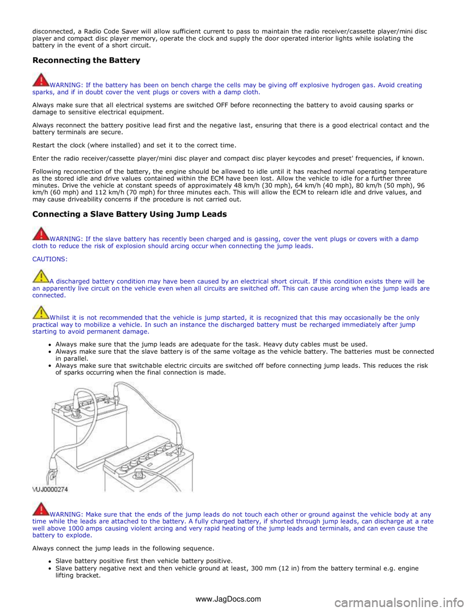
Always connect the jump leads in the following sequence.
Slave battery positive first then vehicle battery positive.
Slave battery negative next and then vehicle ground at least, 300 mm (12 in) from the battery terminal e.g. engine
lifting bracket. www.JagDocs.com
Page 72 of 3039

General Information - Standard Workshop Practices
Description and Operation
Protecting the Vehicle Published: 04-Jul-2014
Always install covers to protect the fenders before commencing work in the engine compartment. Always install the interior
protection kit, wear clean overalls and wash hands or wear gloves before working inside the vehicle. Avoid spilling hydraulic
fluid, antifreeze or battery acid on the paintwork. In the event of spillage, wash off with water immediately. Use polythene
sheets in the luggage compartment to protect carpets. Always use the recommended service tool, or a satisfactory equivalent,
where specified. Protect temporarily exposed screw threads by replacing nuts or installing caps.
Vehicle in Workshop
When working on a vehicle in the workshop always make sure that:
The parking brake is applied or the wheels are securely chocked to prevent the vehicle moving forwards or backwards
If the engine is to be run, there is adequate ventilation, or an extraction hose to remove exhaust fumes is installed
There is adequate room to jack up the vehicle and remove the wheels, if necessary
Fender covers are always installed if any work is to be carried out in the engine compartment
The battery is disconnected if working on the engine, underneath the vehicle, or if the vehicle is jacked up
CAUTION: When electric arc welding on a vehicle, always disconnect the generator wiring to prevent the possibility of a
surge of current causing damage to the internal components of the generator.
If using welding equipment on the vehicle, ensure a suitable fire extinguisher is readily available.
Screw Threads
Damaged nuts, bolts and screws must always be discarded. Attempting to recut or repair damaged threads with a tap
or die impairs the strength and fit of the threads and is not recommended.
NOTES:
During certain repair operations, it may be necessary to remove traces of thread locking agents using a tap. Where this
is necessary, the instruction to do so will appear in the relevant operation and it is essential that a tap of the correct size and
thread is used.
New Taptite bolts when used cut their own threads on the first application.
Some bolts are coated with a thread locking agent and unless stated otherwise, they must not be reused. New bolts
having the same part number as the original must always be installed. When nuts or bolts are to be discarded, the
repair operation and relevant torque chart will include an instruction to that effect. Do not use proprietary thread
locking agents as they may not meet the specification required. See also Encapsulated ('Patched') Bolts and Screws.
Always make sure that replacement nuts and bolts are at least equal in strength to those that they are replacing.
Castellated nuts must not be loosened to accept a split pin except in recommended cases when this forms part of an
adjustment.
Do not allow oil or grease to enter blind holes, the hydraulic action resulting from tightening the bolt or stud can split
the housing and also give a false torque reading.
Always tighten a nut, bolt or screw to the specified torque figure, damaged or corroded threads can give a false torque
reading.
Nut and bolt loosening and tightening sequences, where given, must ALWAYS be followed. Distortion of components or
faulty sealing of joints will result if the sequences are not followed. Where an instruction is given to tighten in stages,
these stages must be adhered to; do not attempt to combine stages particularly where certain stages involve
tightening by degrees.
To check or re-tighten a fixing to a specified torque, first loosen a quarter of a turn, then retighten to the specified
torque figure.
Unless instructed otherwise, do not lubricate bolt or nut threads prior to installing.
Where it is stated that bolts and screws may be reused, the following procedures must be carried out:
Check that threads are undamaged.
Remove all traces of locking agent from the threads.
CAUTION: DO NOT use a wire brush; take care that threads are not damaged.
Make sure that threads are clean and free from oil or grease.
Apply the specified locking agent to the bolt threads.
Page 73 of 3039

Supplementary Restraint System (SRS) Precautions
WARNING: Do not install rear facing child seats in the front passenger seat.
The SRS contains components which are potentially hazardous to service personnel if not handled correctly. The following
guidelines and precautions are intended to alert personnel to potential sources of danger and emphasise the importance of
ensuring the integrity of the SRS components installed to the vehicle.
WARNING: The following precautions MUST be adhered to when working on the SRS system:
The correct procedures must always be used when working on SRS components.
Persons working on the SRS system must be fully trained and have been issued with the safety guidelines.
The airbag modules contain extremely flammable and hazardous compounds. Contact with water, acids or heavy
metals may produce harmful or explosive results. Do not dismantle, incinerate or bring into contact with electricity
before the unit has been deployed.
Always replace a seat belt assembly that has withstood the strain of a severe vehicle impact or if the webbing
shows signs of fraying.
Always disconnect the vehicle battery before carrying out any electric welding on a vehicle installed with an SRS
system.
CAUTION: Do not expose airbag modules or seat belt pre-tensioners to temperatures exceeding 85° C (185° F).
It should be noted that these precautions are not restricted to operations performed when servicing the SRS system. The same
care should be exercised when working on ancillary systems and components located in the vicinity of SRS components; these
include but are not limited to:
Steering wheel airbag, rotary coupler.
Passenger front airbag.
Head airbag modules - front and rear.
Seat belt pre-tensioners.
SRS harnesses, link leads and connectors.
Side (thorax) air bags.
Making the system safe
Before working on or in the vicinity of SRS components, make sure the system is rendered safe by performing the following
operations:
Remove the ignition key.
Disconnect battery, earth lead first.
Wait 2 minutes for the SRS power circuit to discharge before commencing work.
NOTE: The SRS uses energy reserve capacitors to keep the system active in the event of electrical supply failure under
crash conditions. It is necessary to allow the capacitors sufficient time to discharge (2 minutes) in order to avoid the risk of
accidental deployment.
Installation
In order to make sure system integrity, it is essential that the SRS system is regularly checked and maintained so that it is
ready for effective operation in the event of a collision. Carefully inspect SRS components before installation. Do not install a
part that shows signs of being dropped or improperly handled, such as dents, cracks or deformation.
WARNING: The integrity of the SRS systems is critical for safety reasons. Make sure the following precautions are always
adhered to:
Do not install accessories or other objects to trim panels which cover ITS airbags.
Never install used SRS components from another vehicle or attempt to repair an SRS component.
When repairing an SRS system, only use genuine new parts.
Never apply electrical power to an SRS component unless instructed to do so as part of an approved test
procedure.
Special fixings are necessary for installing an airbag module – do not use other fixings and make sure that all
fixings are tightened to the correct torque.
Always use new fixings when replacing an SRS component.
CAUTIONS:
Take care not to trap airbag modules when installing interior trim components.
Make sure SRS components are not contaminated by oil or grease.
NOTES:
Following seat belt pre-tensioner deployment, the seat belts can still be used as conventional seat belts but will need to
Page 95 of 3039

7
Center punch 8
Marker 9
Metal inert gas (MIG) welding equipment 10
Hose clamp 11
Interior trim remover 12
Vacuum cleaner 13
Strap wrench 14
Wedge 15
Pin Punch Material symbols
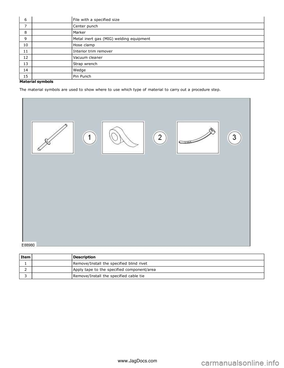
The material symbols are used to show where to use which type of material to carry out a procedure step.
Item
Description 1
Remove/Install the specified blind rivet 2
Apply tape to the specified component/area 3
Remove/Install the specified cable tie www.JagDocs.com
Page 223 of 3039

DTC Description Possible Causes Action or short to power short to power B1124-11
Lamp Fade Control -
Circuit short to ground
Interior lamp fade
control circuit - short to
ground
Refer to the electrical circuit diagrams and check
interior lamp fade control circuit for short to ground B1124-12
Lamp Fade Control -
Circuit short to battery
Interior lamp fade
control circuit - short to
power
Refer to the electrical circuit diagrams and check
interior lamp fade control circuit for short to power B113C-12
Hazard Switch
Illumination - Circuit
short to battery
Hazard switch
illumination control
circuit - short to power
Refer to the electrical circuit diagrams and check
hazard switch illumination control circuit for short to
power B113C-14
Hazard Switch
Illumination - Circuit
short to ground or open
Hazard switch
illumination control
circuit - short to ground,
open circuit
Refer to the electrical circuit diagrams and check
hazard switch illumination control circuit for short to
ground, open circuit B113E-12
External Boot/Trunk
Release Switch - Circuit
short to battery
External luggage
compartment lid release
switch digital input
circuit - short to power
Refer to the electrical circuit diagrams and check
external luggage compartment lid release switch
digital input circuit for short to power B113E-23
External Boot/Trunk
Release Switch - Signal
stuck low
External luggage
compartment lid release
switch digital input
circuit - signal stuck low
Carry out any pinpoint test associated with this DTC
using the manufacturer approved diagnostic system.
Refer to the electrical circuit diagrams and check
external luggage compartment lid release switch
digital input circuit for short to ground B11D9-49
Vehicle Battery -
Internal electronic
failure
Vehicle battery
damaged/worn out
Check battery is in fully charged and serviceable
condition using the Midtronics battery tester and
the battery care manual B11DB-49
Battery Monitoring
Module - Internal
electronic failure
Internal electronic
failure
Suspect the battery monitoring module. Check and
install a new module as required, refer to the new
module/component installation note at the top of
the DTC Index B11DB-87
Battery Monitoring
Module - Missing
message
Battery monitoring
module connector
dis-connected/poor
connection
Battery monitoring
module to RJB LIN
circuit - open circuit
Battery monitoring
module to battery
positive monitor circuit -
open circuit
Battery monitoring
module/RJB failure
Carry out any pinpoint test associated with this DTC
using the manufacturer approved diagnostic system.
If additional DTCs B108783, B108786, B108787 are
logged, suspect the RJB. Check and install a new
RJB as required, refer to the new module/component
installation note at the top of the DTC Index. If
additional DTCs B108783, B108786, B108787 are
NOT logged, check for good/clean contact at battery
monitoring module connector, refer to electrical
circuit diagrams and check battery monitoring
module to RJB LIN circuit and battery monitoring
module to battery positive monitor circuit for open
circuit. Clear DTC and repeat automated diagnostic
procedure using manufacturer approved diagnostic
system. If DTC remains suspect the battery
monitoring module, check and install a new battery
monitoring module as required, refer to the new
module/component installation note at the top of
the DTC Index B123A-11 Left Front Turn Indicator
- Circuit short to ground
Left front turn signal
lamp control circuit -
short to ground
Refer to the electrical circuit diagrams and check left
front turn signal lamp control circuit for short to
ground B123A-12 Left Front Turn Indicator
- Circuit short to battery
Left front turn signal
lamp control circuit -
short to power
Refer to the electrical circuit diagrams and check left
front turn signal lamp control circuit for short to
power
Page 228 of 3039

DTC Description Possible Causes Action B10C2-00
Left Rear Unlock Pull
Switch - No sub type
information
No power supply to door
handle
Switch circuit open, or
short circuit to power
Carry out any pinpoint tests associated with this
DTC using the manufacturer approved diagnostic
system. Refer to the electrical circuit diagrams and
check the power supply to the door handle. Check
the switch circuit is not open circuit or short to
power. Repair wiring as required B10C2-24
Left Rear Unlock Pull
Switch - Signal stuck
high
Signal stuck high - button
stuck in active position
Carry out any pinpoint tests associated with this
DTC using the manufacturer approved diagnostic
system. Check for stuck left rear unlock switch.
Refer to the electrical circuit diagrams and check
left rear unlock switch circuit for short to ground B10C3-00
Right Front Unlock Pull
Switch - No sub type
information
No power supply to door
handle
Switch circuit open, or
short circuit to power
Carry out any pinpoint tests associated with this
DTC using the manufacturer approved diagnostic
system. Refer to the electrical circuit diagrams and
check the power supply to the door handle. Check
the switch circuit is not open circuit or short to
power. Repair wiring as required B10C3-24
Right Front Unlock Pull
Switch - Signal stuck
high
Signal stuck high - button
stuck in active position
Carry out any pinpoint tests associated with this
DTC using the manufacturer approved diagnostic
system. Check for stuck right front unlock switch.
Refer to the electrical circuit diagrams and check
right front unlock switch circuit for short to ground B10C4-00
Right Rear Unlock Pull
Switch - No sub type
information
No power supply to door
handle
Switch circuit open, or
short circuit to power
Carry out any pinpoint tests associated with this
DTC using the manufacturer approved diagnostic
system. Refer to the electrical circuit diagrams and
check the power supply to the door handle. Check
the switch circuit is not open circuit or short to
power. Repair wiring as required B10C4-24
Right Rear Unlock Pull
Switch - Signal stuck
high
Signal stuck high - button
stuck in active position
Carry out any pinpoint tests associated with this
DTC using the manufacturer approved diagnostic
system. Check for stuck right rear unlock switch.
Refer to the electrical circuit diagrams and check
right front unlock switch circuit for short to ground B10C5-24 Trunk Unlock Pull
Switch - Signal stuck
high
Signal stuck high - button
stuck in active position
Carry out any pinpoint tests associated with this
DTC using the manufacturer approved diagnostic
system. Check for stuck luggage compartment lid
unlock switch. Refer to the electrical circuit diagrams
and check luggage compartment lid unlock
switch circuit for short to ground B10C6-1F Exterior Trunk Antenna
- Circuit intermittent
Circuit intermittent -
general electrical error
Carry out any pinpoint tests associated with this
DTC using the manufacturer approved diagnostic
system. Refer to the electrical circuit diagrams and
check exterior luggage compartment antenna
circuits for short to ground, power, open circuit B10C7-1F Interior Trunk Antenna
- Circuit intermittent
Circuit intermittent -
general electrical error
Carry out any pinpoint tests associated with this
DTC using the manufacturer approved diagnostic
system. Refer to the electrical circuit diagrams and
check interior luggage compartment antenna circuits
for short to ground, power, open circuit B10C8-1F
Interior Center
Antenna - Circuit
intermittent
Circuit intermittent -
general electrical error
Carry out any pinpoint tests associated with this
DTC using the manufacturer approved diagnostic
system. Refer to the electrical circuit diagrams and
check interior center antenna circuits for short to
ground, power, open circuit B10C9-1F Interior Front Antenna
- Circuit intermittent
Circuit intermittent -
general electrical error
Carry out any pinpoint tests associated with this
DTC using the manufacturer approved diagnostic
system. Refer to the electrical circuit diagrams and
check interior front antenna circuits for short to