Interior JAGUAR XFR 2010 1.G Workshop Manual
[x] Cancel search | Manufacturer: JAGUAR, Model Year: 2010, Model line: XFR, Model: JAGUAR XFR 2010 1.GPages: 3039, PDF Size: 58.49 MB
Page 2542 of 3039
On vehicles with headlamp powerwash, each headlamp assembly is fitted with a headlamp powerwasher. The powerwasher is
located on the underside of the headlamp assembly. The powerwasher is located in a clip at the front of the headlamp and
secured with 2 self tapping screws to the headlamp body.
The powerwasher is a telescopic unit which extends forwards from the headlamp assembly under washer fluid pressure
supplied by the headlamp powerwash pump. When the pump pressure decreases the powerwasher is automatically retracted
back into the housing. The outer end of the powerwasher is fitted with a trim which blends the powerwasher into the headlamp
when it is not operating. The powerwasher has two washer jets which direct washer fluid under high pressure onto the
headlamp lens when the powerwasher is extended.
RAIN/LIGHT SENSOR
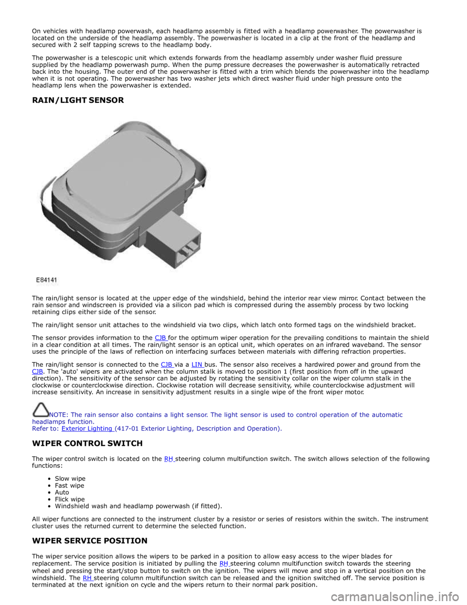
The rain/light sensor is located at the upper edge of the windshield, behind the interior rear view mirror. Contact between the
rain sensor and windscreen is provided via a silicon pad which is compressed during the assembly process by two locking
retaining clips either side of the sensor.
The rain/light sensor unit attaches to the windshield via two clips, which latch onto formed tags on the windshield bracket.
The sensor provides information to the CJB for the optimum wiper operation for the prevailing conditions to maintain the shield in a clear condition at all times. The rain/light sensor is an optical unit, which operates on an infrared waveband. The sensor
uses the principle of the laws of reflection on interfacing surfaces between materials with differing refraction properties.
The rain/light sensor is connected to the CJB via a LIN bus. The sensor also receives a hardwired power and ground from the CJB. The 'auto' wipers are activated when the column stalk is moved to position 1 (first position from off in the upward direction). The sensitivity of the sensor can be adjusted by rotating the sensitivity collar on the wiper column stalk in the
clockwise or counterclockwise direction. Clockwise rotation will decrease sensitivity, while counterclockwise adjustment will
increase sensitivity. An increase in sensitivity adjustment results in a single wipe of the front wiper motor.
NOTE: The rain sensor also contains a light sensor. The light sensor is used to control operation of the automatic
headlamps function.
Refer to: Exterior Lighting (417-01 Exterior Lighting, Description and Operation).
WIPER CONTROL SWITCH
The wiper control switch is located on the RH steering column multifunction switch. The switch allows selection of the following functions:
Slow wipe
Fast wipe
Auto
Flick wipe
Windshield wash and headlamp powerwash (if fitted).
All wiper functions are connected to the instrument cluster by a resistor or series of resistors within the switch. The instrument
cluster uses the returned current to determine the selected function.
WIPER SERVICE POSITION
The wiper service position allows the wipers to be parked in a position to allow easy access to the wiper blades for
replacement. The service position is initiated by pulling the RH steering column multifunction switch towards the steering wheel and pressing the start/stop button to switch on the ignition. The wipers will move and stop in a vertical position on the
windshield. The RH steering column multifunction switch can be released and the ignition switched off. The service position is terminated at the next ignition on cycle and the wipers return to their normal park position.
Page 2549 of 3039

Wipers and Washers - Rain Sensor
Removal and Installation
Removal
NOTE: Removal steps in this procedure may contain installation details. Published: 11-May-2011
1. Refer to: Interior Rear View Mirror (501-09 Rear View Mirrors, Removal and Installation).
2.
3.
Installation
1. CAUTIONS:
Make sure that the component is secured in the
retainer.
Make sure that the clips are correctly located.
To install, reverse the removal procedure. www.JagDocs.com
Page 2568 of 3039
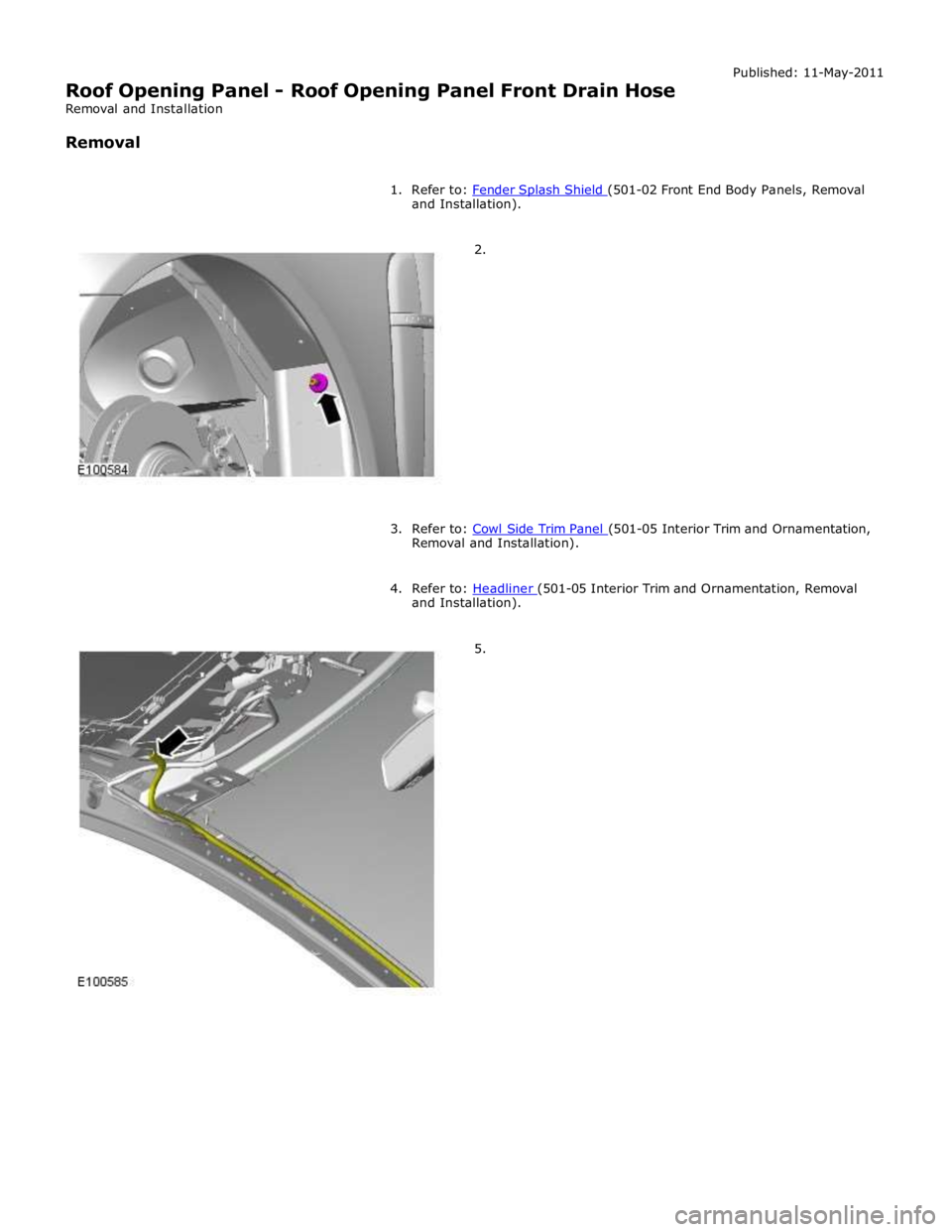
and Installation).
2.
3. Refer to: Cowl Side Trim Panel (501-05 Interior Trim and Ornamentation, Removal and Installation).
4. Refer to: Headliner (501-05 Interior Trim and Ornamentation, Removal and Installation).
5.
Page 2570 of 3039
Roof Opening Panel - Roof Opening Panel Frame
Removal and Installation
Removal
NOTE: Removal steps in this procedure may contain installation details. Published: 11-May-2011
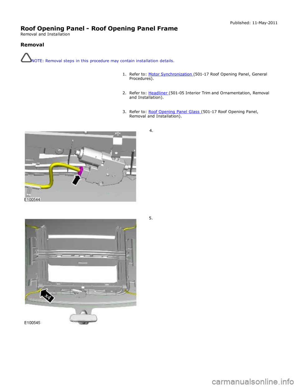
1. Refer to: Motor Synchronization (501-17 Roof Opening Panel, General Procedures).
2. Refer to: Headliner (501-05 Interior Trim and Ornamentation, Removal and Installation).
3. Refer to: Roof Opening Panel Glass (501-17 Roof Opening Panel, Removal and Installation).
4.
5.
Page 2576 of 3039
Roof Opening Panel - Roof Opening Panel Rear Drain Hose
Removal and Installation
Removal Published: 11-May-2011
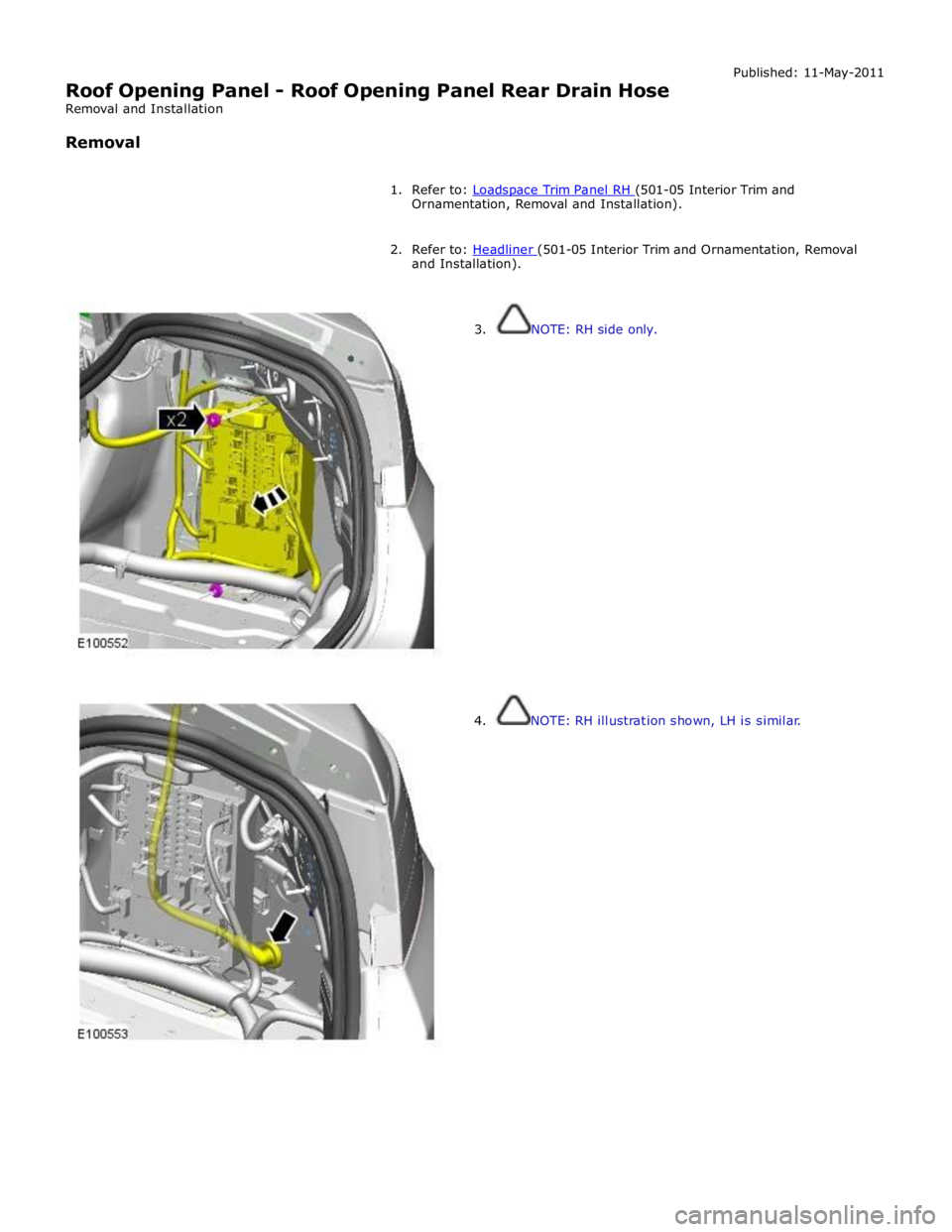
1. Refer to: Loadspace Trim Panel RH (501-05 Interior Trim and Ornamentation, Removal and Installation).
2. Refer to: Headliner (501-05 Interior Trim and Ornamentation, Removal and Installation).
3. NOTE: RH side only.
4. NOTE: RH illustration shown, LH is similar.
Page 2601 of 3039
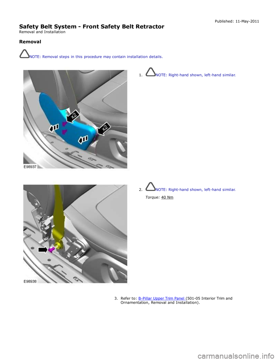
Safety Belt System - Front Safety Belt Retractor
Removal and Installation
Removal
NOTE: Removal steps in this procedure may contain installation details. Published: 11-May-2011
1. NOTE: Right-hand shown, left-hand similar.
2. NOTE: Right-hand shown, left-hand similar.
Torque: 40 Nm
3. Refer to: B-Pillar Upper Trim Panel (501-05 Interior Trim and Ornamentation, Removal and Installation).
Page 2604 of 3039
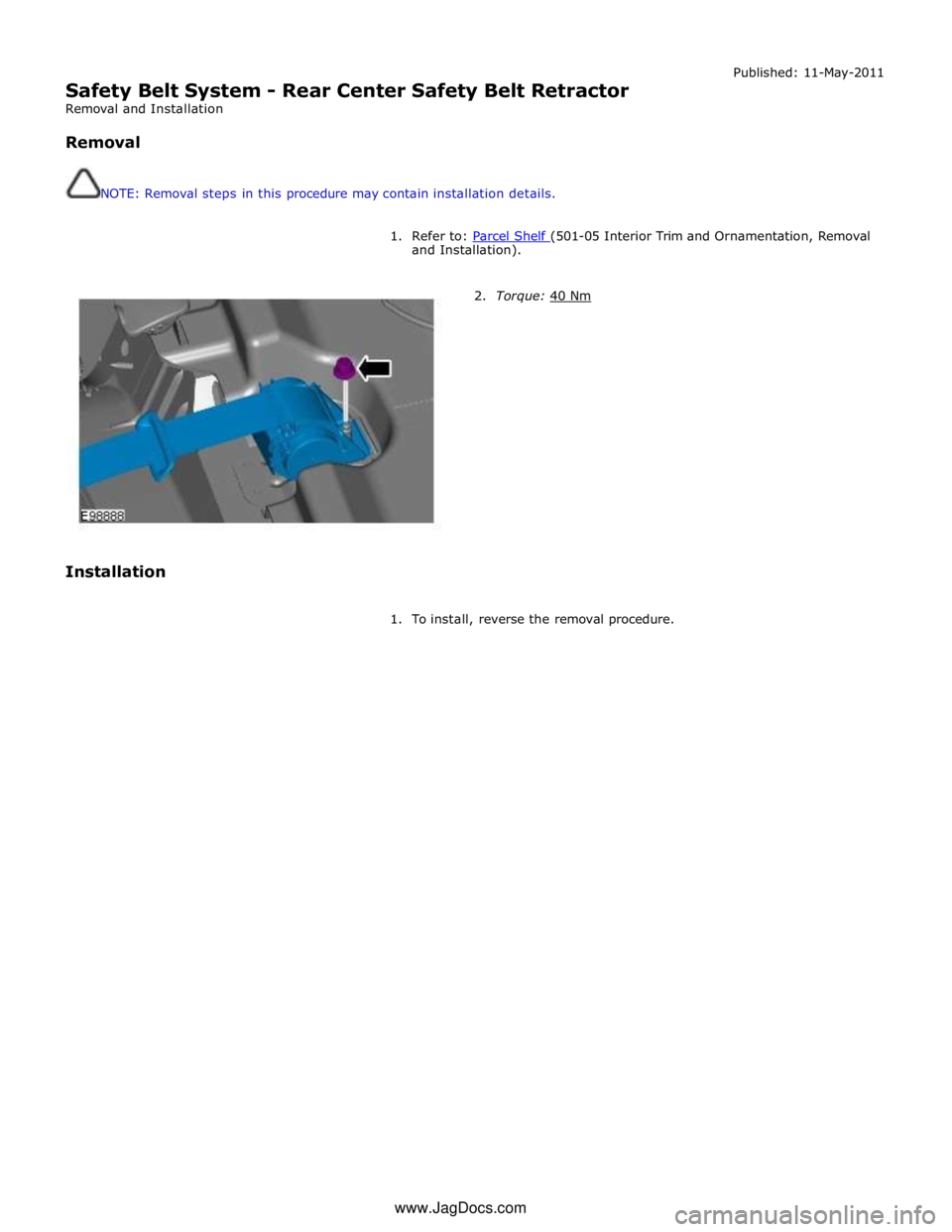
Safety Belt System - Rear Center Safety Belt Retractor
Removal and Installation
Removal
NOTE: Removal steps in this procedure may contain installation details. Published: 11-May-2011
1. Refer to: Parcel Shelf (501-05 Interior Trim and Ornamentation, Removal and Installation).
Installation
2. Torque: 40 Nm
1. To install, reverse the removal procedure. www.JagDocs.com
Page 2606 of 3039
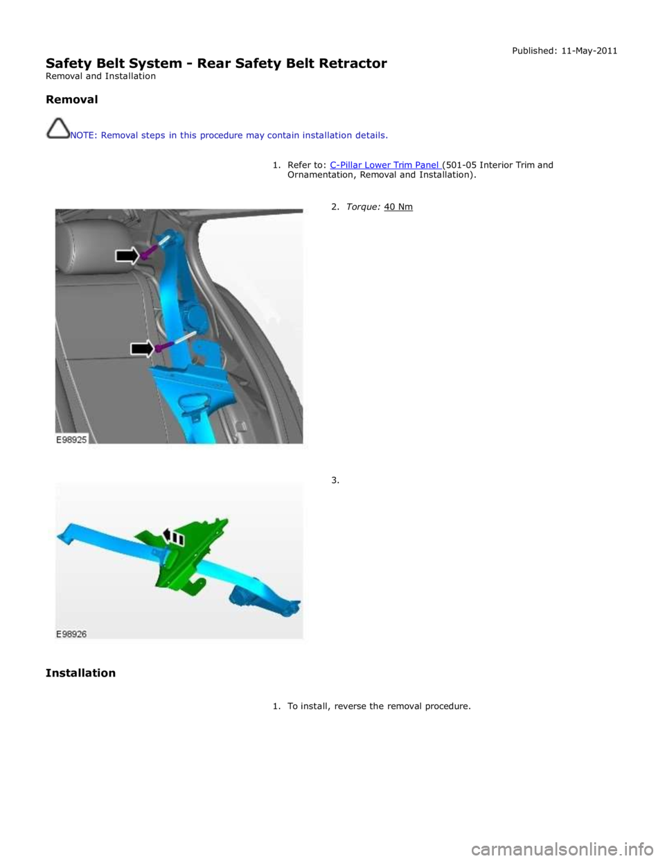
Safety Belt System - Rear Safety Belt Retractor
Removal and Installation
Removal
NOTE: Removal steps in this procedure may contain installation details. Published: 11-May-2011
1. Refer to: C-Pillar Lower Trim Panel (501-05 Interior Trim and Ornamentation, Removal and Installation).
Installation
2. Torque: 40 Nm
3.
1. To install, reverse the removal procedure.
Page 2607 of 3039
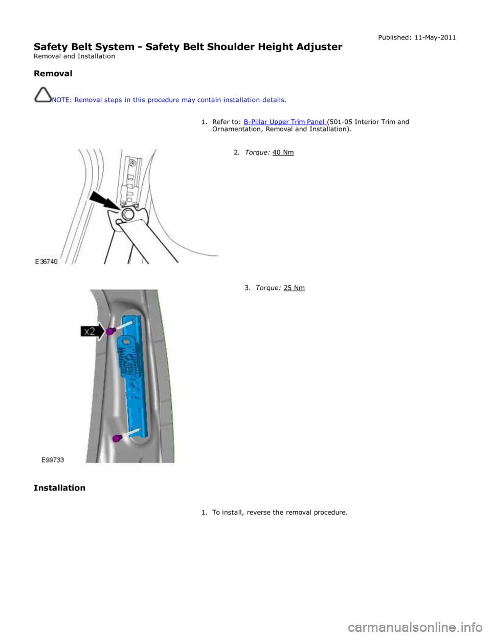
Safety Belt System - Safety Belt Shoulder Height Adjuster
Removal and Installation
Removal
NOTE: Removal steps in this procedure may contain installation details. Published: 11-May-2011
1. Refer to: B-Pillar Upper Trim Panel (501-05 Interior Trim and Ornamentation, Removal and Installation).
2. Torque: 40 Nm
Installation
3. Torque: 25 Nm
1. To install, reverse the removal procedure.
Page 2615 of 3039
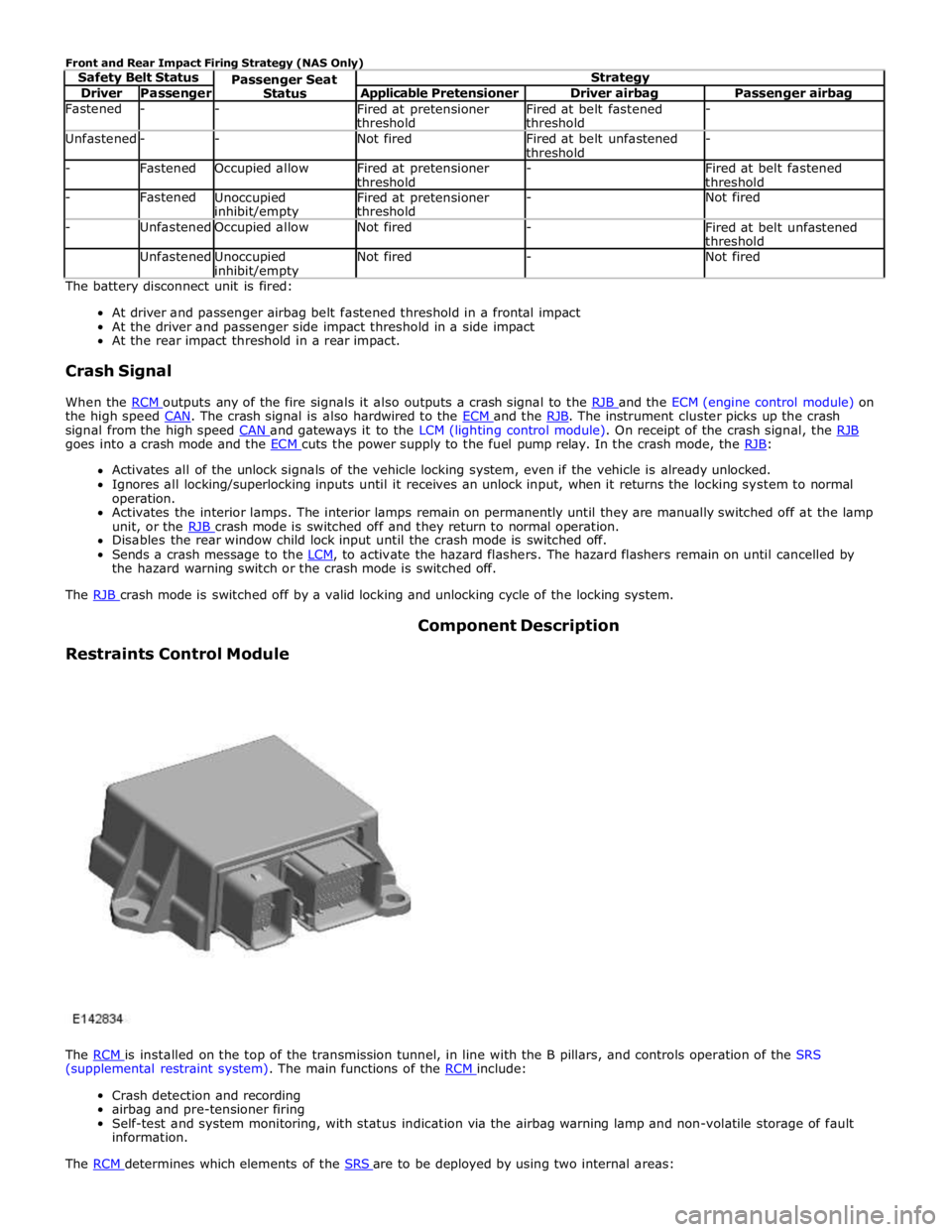
Driver Passenger Applicable Pretensioner Driver airbag Passenger airbag Fastened - -
Fired at pretensioner
threshold Fired at belt fastened
threshold - Unfastened - - Not fired
Fired at belt unfastened
threshold - - Fastened Occupied allow
Fired at pretensioner
threshold -
Fired at belt fastened
threshold - Fastened
Unoccupied inhibit/empty Fired at pretensioner
threshold - Not fired - Unfastened Occupied allow Not fired -
Fired at belt unfastened
threshold Unfastened
Unoccupied inhibit/empty Not fired - Not fired The battery disconnect unit is fired:
At driver and passenger airbag belt fastened threshold in a frontal impact
At the driver and passenger side impact threshold in a side impact
At the rear impact threshold in a rear impact.
Crash Signal
When the RCM outputs any of the fire signals it also outputs a crash signal to the RJB and the ECM (engine control module) on the high speed CAN. The crash signal is also hardwired to the ECM and the RJB. The instrument cluster picks up the crash signal from the high speed CAN and gateways it to the LCM (lighting control module). On receipt of the crash signal, the RJB goes into a crash mode and the ECM cuts the power supply to the fuel pump relay. In the crash mode, the RJB: Activates all of the unlock signals of the vehicle locking system, even if the vehicle is already unlocked.
Ignores all locking/superlocking inputs until it receives an unlock input, when it returns the locking system to normal
operation.
Activates the interior lamps. The interior lamps remain on permanently until they are manually switched off at the lamp
unit, or the RJB crash mode is switched off and they return to normal operation. Disables the rear window child lock input until the crash mode is switched off.
Sends a crash message to the LCM, to activate the hazard flashers. The hazard flashers remain on until cancelled by the hazard warning switch or the crash mode is switched off.
The RJB crash mode is switched off by a valid locking and unlocking cycle of the locking system.
Restraints Control Module Component Description
The RCM is installed on the top of the transmission tunnel, in line with the B pillars, and controls operation of the SRS (supplemental restraint system). The main functions of the RCM include:
Crash detection and recording
airbag and pre-tensioner firing
Self-test and system monitoring, with status indication via the airbag warning lamp and non-volatile storage of fault
information.
The RCM determines which elements of the SRS are to be deployed by using two internal areas: