Engine JAGUAR XFR 2010 1.G Workshop Manual
[x] Cancel search | Manufacturer: JAGUAR, Model Year: 2010, Model line: XFR, Model: JAGUAR XFR 2010 1.GPages: 3039, PDF Size: 58.49 MB
Page 841 of 3039
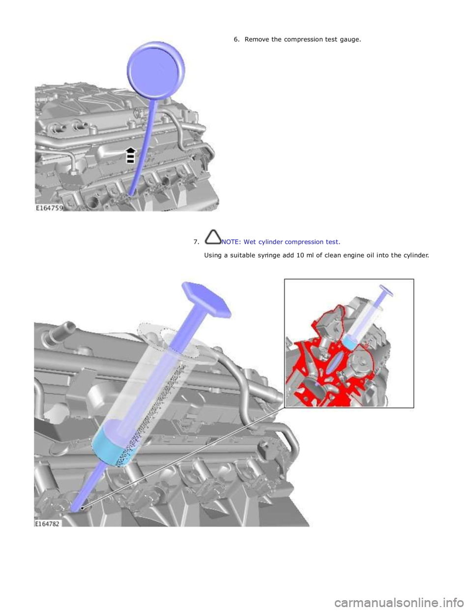
6. Remove the compression test gauge.
7. NOTE: Wet cylinder compression test.
Using a suitable syringe add 10 ml of clean engine oil into the cylinder.
Page 842 of 3039
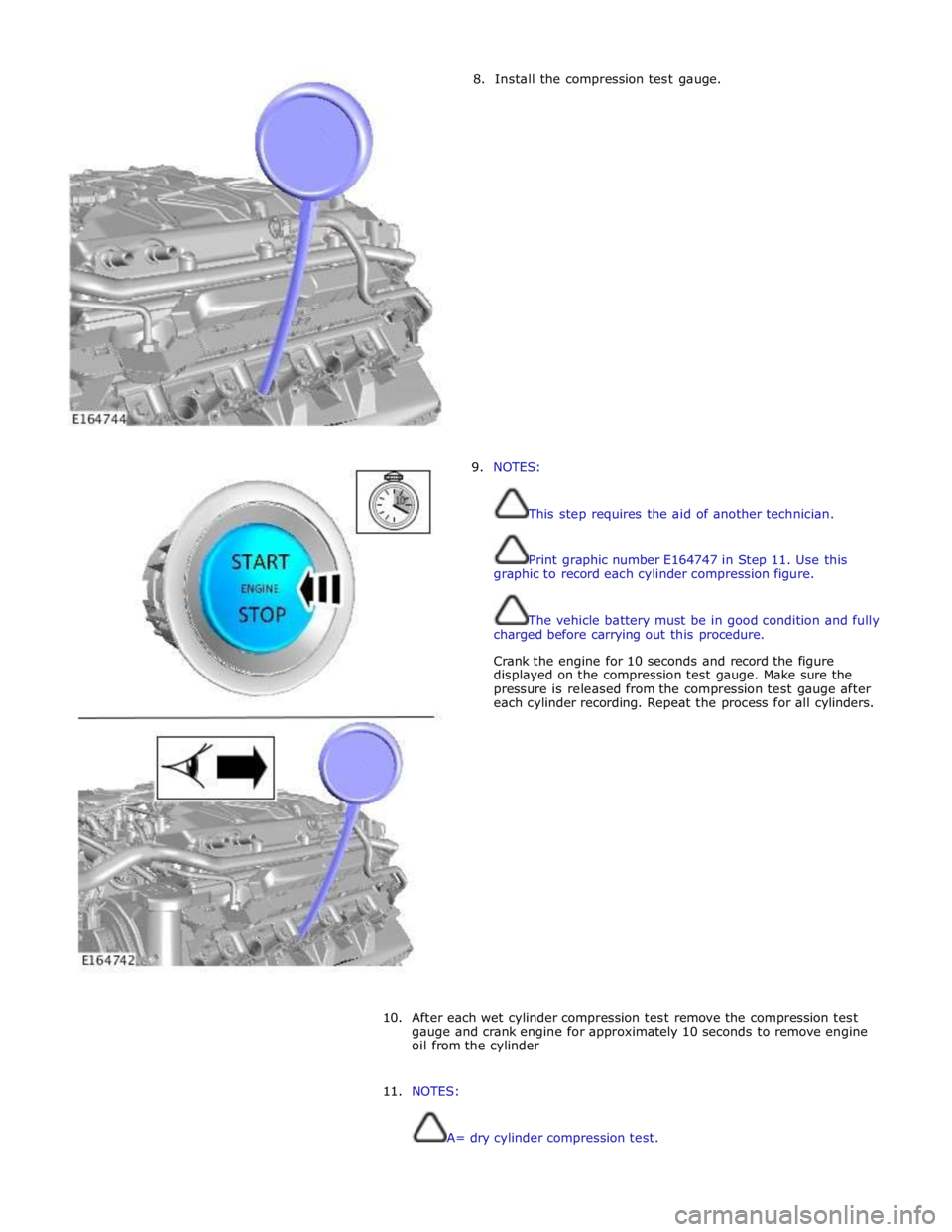
8. Install the compression test gauge.
9. NOTES:
This step requires the aid of another technician.
Print graphic number E164747 in Step 11. Use this
graphic to record each cylinder compression figure.
The vehicle battery must be in good condition and fully
charged before carrying out this procedure.
Crank the engine for 10 seconds and record the figure
displayed on the compression test gauge. Make sure the
pressure is released from the compression test gauge after
each cylinder recording. Repeat the process for all cylinders.
10.
After each wet cylinder compression test remove the compression test
gauge and crank engine for approximately 10 seconds to remove engine
oil from the cylinder
11. NOTES:
A= dry cylinder compression test.
Page 844 of 3039
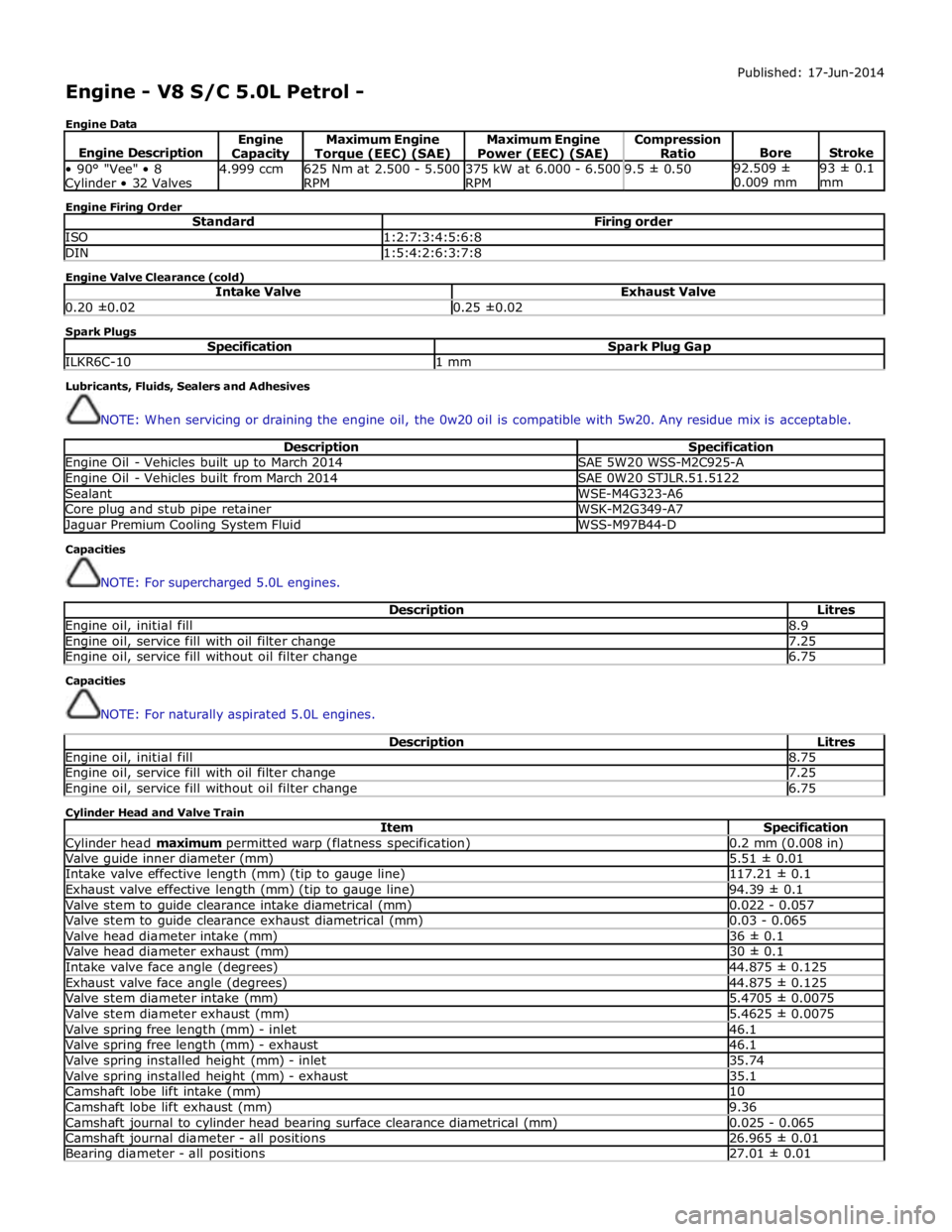
Engine - V8 S/C 5.0L Petrol -
Engine Data Published: 17-Jun-2014
Engine Description Engine Capacity Maximum Engine Torque (EEC) (SAE) Maximum Engine
Power (EEC) (SAE) Compression
Ratio
Bore
Stroke • 90° "Vee" • 8 Cylinder • 32 Valves 4.999 ccm
625 Nm at 2.500 - 5.500
RPM 375 kW at 6.000 - 6.500
RPM 9.5 ± 0.50 92.509 ±
0.009 mm 93 ± 0.1
mm Engine Firing Order
Standard Firing order ISO 1:2:7:3:4:5:6:8 DIN 1:5:4:2:6:3:7:8 Engine Valve Clearance (cold)
Intake Valve Exhaust Valve 0.20 ±0.02 0.25 ±0.02 Spark Plugs
Specification Spark Plug Gap ILKR6C-10 1 mm Lubricants, Fluids, Sealers and Adhesives
NOTE: When servicing or draining the engine oil, the 0w20 oil is compatible with 5w20. Any residue mix is acceptable.
Description Specification Engine Oil - Vehicles built up to March 2014 SAE 5W20 WSS-M2C925-A Engine Oil - Vehicles built from March 2014 SAE 0W20 STJLR.51.5122 Sealant WSE-M4G323-A6 Core plug and stub pipe retainer WSK-M2G349-A7 Jaguar Premium Cooling System Fluid WSS-M97B44-D Capacities
NOTE: For supercharged 5.0L engines.
Description Litres Engine oil, initial fill 8.9 Engine oil, service fill with oil filter change 7.25 Engine oil, service fill without oil filter change 6.75 Capacities
NOTE: For naturally aspirated 5.0L engines.
Description Litres Engine oil, initial fill 8.75 Engine oil, service fill with oil filter change 7.25 Engine oil, service fill without oil filter change 6.75 Cylinder Head and Valve Train
Item Specification Cylinder head maximum permitted warp (flatness specification) 0.2 mm (0.008 in) Valve guide inner diameter (mm) 5.51 ± 0.01 Intake valve effective length (mm) (tip to gauge line) 117.21 ± 0.1 Exhaust valve effective length (mm) (tip to gauge line) 94.39 ± 0.1 Valve stem to guide clearance intake diametrical (mm) 0.022 - 0.057 Valve stem to guide clearance exhaust diametrical (mm) 0.03 - 0.065 Valve head diameter intake (mm) 36 ± 0.1 Valve head diameter exhaust (mm) 30 ± 0.1 Intake valve face angle (degrees) 44.875 ± 0.125 Exhaust valve face angle (degrees) 44.875 ± 0.125 Valve stem diameter intake (mm) 5.4705 ± 0.0075 Valve stem diameter exhaust (mm) 5.4625 ± 0.0075 Valve spring free length (mm) - inlet 46.1 Valve spring free length (mm) - exhaust 46.1 Valve spring installed height (mm) - inlet 35.74 Valve spring installed height (mm) - exhaust 35.1 Camshaft lobe lift intake (mm) 10 Camshaft lobe lift exhaust (mm) 9.36 Camshaft journal to cylinder head bearing surface clearance diametrical (mm) 0.025 - 0.065 Camshaft journal diameter - all positions 26.965 ± 0.01 Bearing diameter - all positions 27.01 ± 0.01
Page 845 of 3039
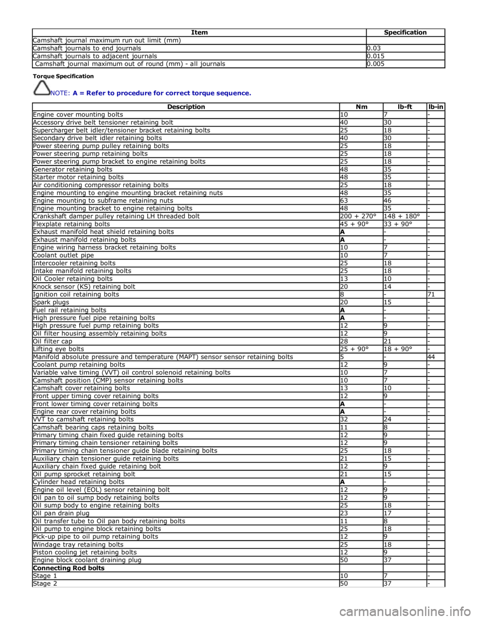
Item Specification Camshaft journal maximum run out limit (mm) Camshaft journals to end journals 0.03 Camshaft journals to adjacent journals 0.015 Camshaft journal maximum out of round (mm) - all journals 0.005 Torque Specification
NOTE: A = Refer to procedure for correct torque sequence.
Description Nm lb-ft lb-in Engine cover mounting bolts 10 7 - Accessory drive belt tensioner retaining bolt 40 30 - Supercharger belt idler/tensioner bracket retaining bolts 25 18 - Secondary drive belt idler retaining bolts 40 30 - Power steering pump pulley retaining bolts 25 18 - Power steering pump retaining bolts 25 18 - Power steering pump bracket to engine retaining bolts 25 18 - Generator retaining bolts 48 35 - Starter motor retaining bolts 48 35 - Air conditioning compressor retaining bolts 25 18 - Engine mounting to engine mounting bracket retaining nuts 48 35 - Engine mounting to subframe retaining nuts 63 46 - Engine mounting bracket to engine retaining bolts 48 35 - Crankshaft damper pulley retaining LH threaded bolt 200 + 270° 148 + 180° - Flexplate retaining bolts 45 + 90° 33 + 90° - Exhaust manifold heat shield retaining bolts A - - Exhaust manifold retaining bolts A - - Engine wiring harness bracket retaining bolts 10 7 - Coolant outlet pipe 10 7 - Intercooler retaining bolts 25 18 - Intake manifold retaining bolts 25 18 - Oil Cooler retaining bolts 13 10 - Knock sensor (KS) retaining bolt 20 14 - Ignition coil retaining bolts 8 - 71 Spark plugs 20 15 - Fuel rail retaining bolts A - - High pressure fuel pipe retaining bolts A - - High pressure fuel pump retaining bolts 12 9 - Oil filter housing assembly retaining bolts 12 9 - Oil filter cap 28 21 - Lifting eye bolts 25 + 90° 18 + 90° - Manifold absolute pressure and temperature (MAPT) sensor sensor retaining bolts 5 - 44 Coolant pump retaining bolts 12 9 - Variable valve timing (VVT) oil control solenoid retaining bolts 10 7 - Camshaft position (CMP) sensor retaining bolts 10 7 - Camshaft cover retaining bolts 13 10 - Front upper timing cover retaining bolts 12 9 - Front lower timing cover retaining bolts A - - Engine rear cover retaining bolts A - - VVT to camshaft retaining bolts 32 24 - Camshaft bearing caps retaining bolts 11 8 - Primary timing chain fixed guide retaining bolts 12 9 - Primary timing chain tensioner retaining bolts 12 9 - Primary timing chain tensioner guide blade retaining bolts 25 18 - Auxiliary chain tensioner guide retaining bolts 21 15 - Auxiliary chain fixed guide retaining bolt 12 9 - Oil pump sprocket retaining bolt 21 15 - Cylinder head retaining bolts A - - Engine oil level (EOL) sensor retaining bolt 12 9 - Oil pan to oil sump body retaining bolts 12 9 - Oil sump body to engine retaining bolts 25 18 - Oil pan drain plug 23 17 - Oil transfer tube to Oil pan body retaining bolts 11 8 - Oil pump to engine block retaining bolts 25 18 - Pick-up pipe to oil pump retaining bolts 12 9 - Windage tray retaining bolts 25 18 - Piston cooling jet retaining bolts 12 9 - Engine block coolant draining plug 50 37 - Connecting Rod bolts Stage 1 10 7 - Stage 2 50 37 -
Page 847 of 3039
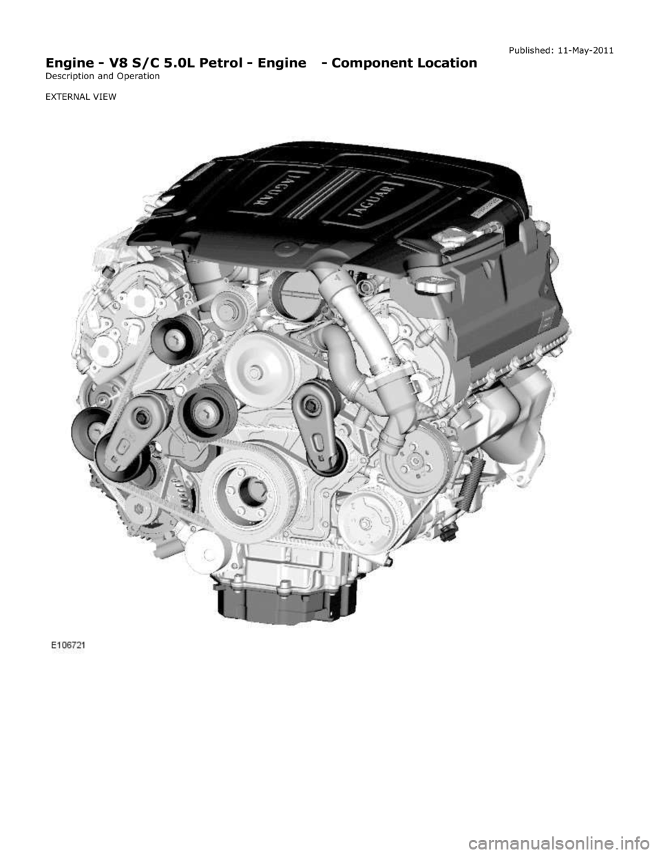
Engine - V8 S/C 5.0L Petrol - Engine - Component Location
Description and Operation
EXTERNAL VIEW Published: 11-May-2011
Page 851 of 3039
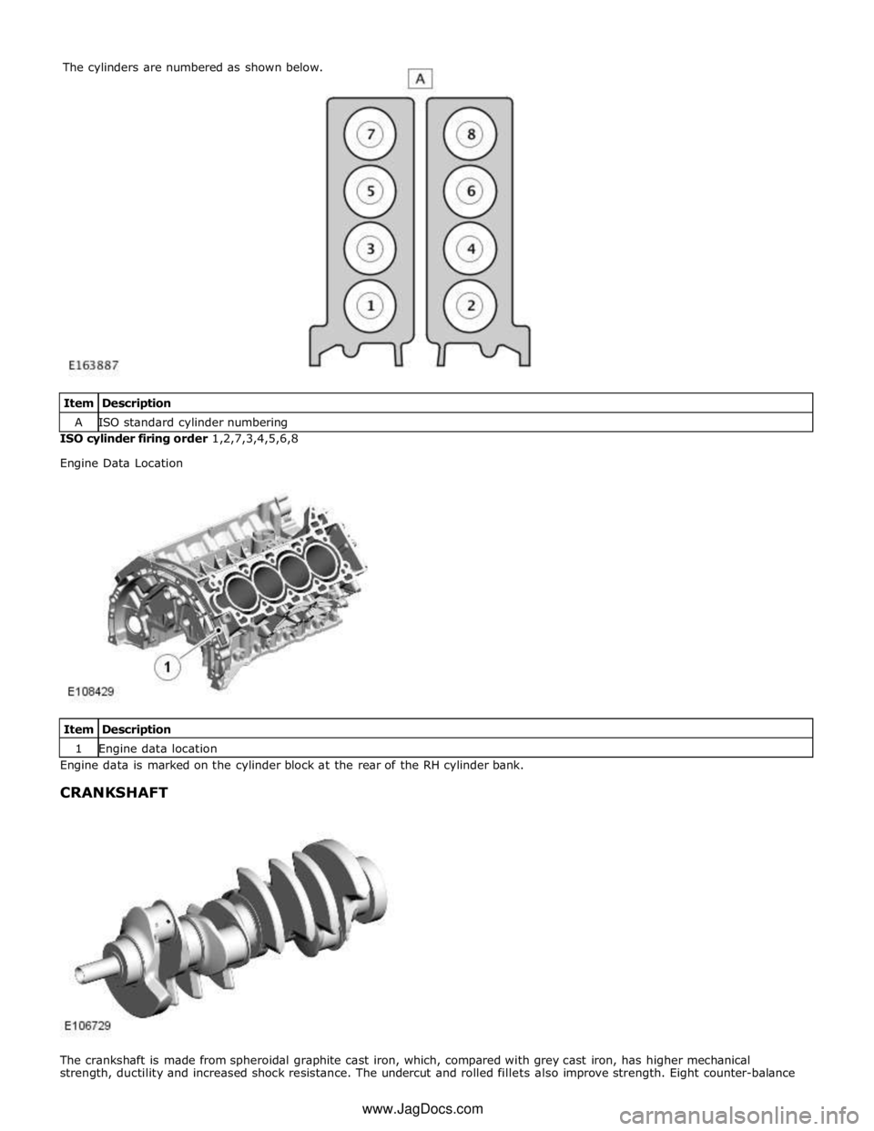
A ISO standard cylinder numbering ISO cylinder firing order 1,2,7,3,4,5,6,8
Engine Data Location
Item Description 1 Engine data location Engine data is marked on the cylinder block at the rear of the RH cylinder bank.
CRANKSHAFT
The crankshaft is made from spheroidal graphite cast iron, which, compared with grey cast iron, has higher mechanical
strength, ductility and increased shock resistance. The undercut and rolled fillets also improve strength. Eight counter-balance The cylinders are numbered as shown below.
www.JagDocs.com
Page 852 of 3039
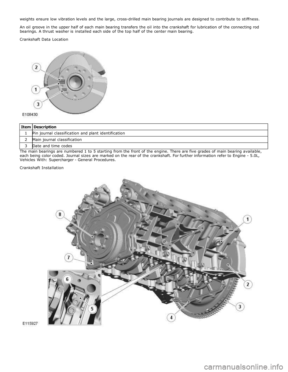
1 Pin journal classification and plant identification 2 Main journal classification 3 Date and time codes The main bearings are numbered 1 to 5 starting from the front of the engine. There are five grades of main bearing available,
each being color coded. Journal sizes are marked on the rear of the crankshaft. For further information refer to Engine - 5.0L,
Vehicles With: Supercharger - General Procedures.
Crankshaft Installation
Page 853 of 3039
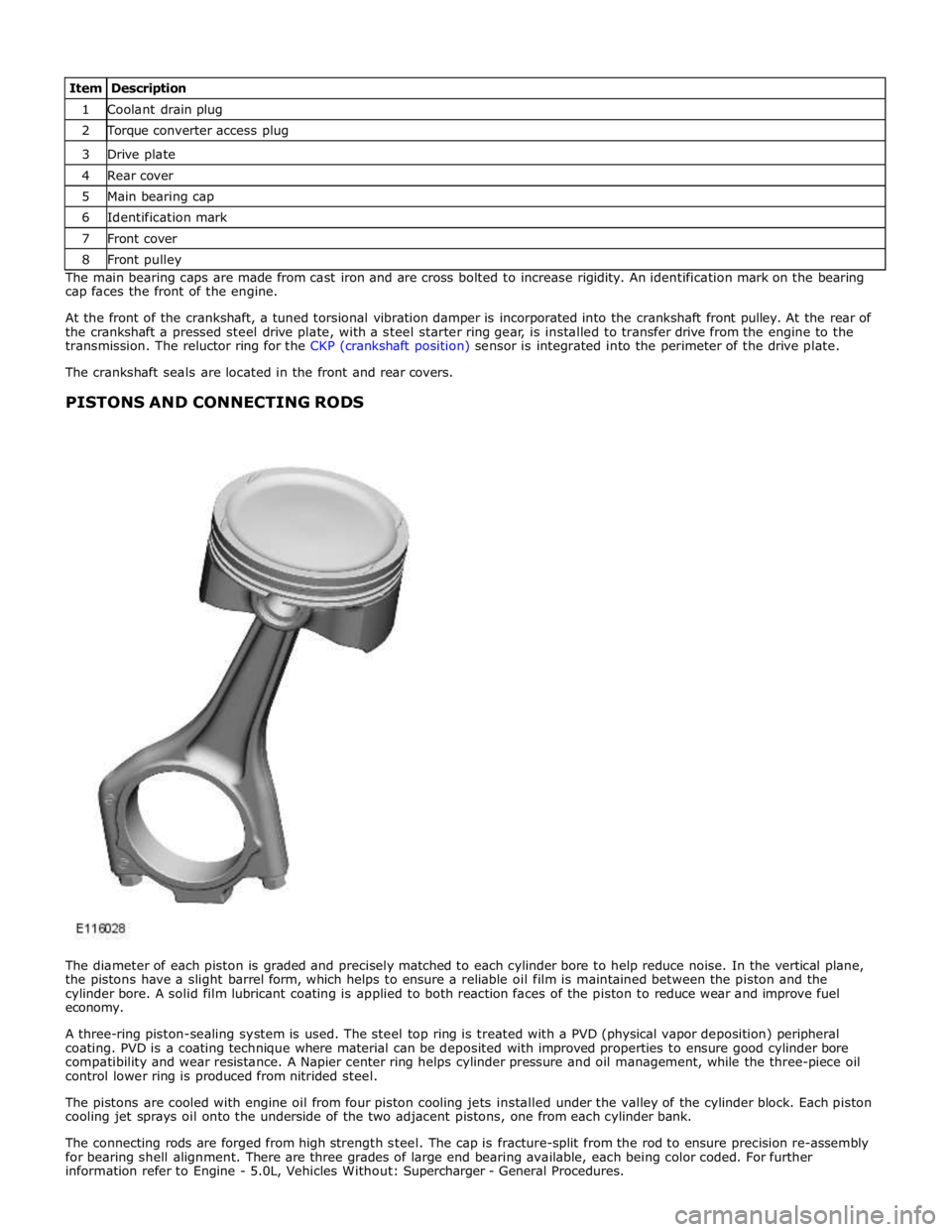
1 Coolant drain plug 2 Torque converter access plug 3 Drive plate 4 Rear cover 5 Main bearing cap 6 Identification mark 7 Front cover 8 Front pulley The main bearing caps are made from cast iron and are cross bolted to increase rigidity. An identification mark on the bearing
cap faces the front of the engine.
At the front of the crankshaft, a tuned torsional vibration damper is incorporated into the crankshaft front pulley. At the rear of
the crankshaft a pressed steel drive plate, with a steel starter ring gear, is installed to transfer drive from the engine to the
transmission. The reluctor ring for the CKP (crankshaft position) sensor is integrated into the perimeter of the drive plate.
The crankshaft seals are located in the front and rear covers.
PISTONS AND CONNECTING RODS
The diameter of each piston is graded and precisely matched to each cylinder bore to help reduce noise. In the vertical plane,
the pistons have a slight barrel form, which helps to ensure a reliable oil film is maintained between the piston and the
cylinder bore. A solid film lubricant coating is applied to both reaction faces of the piston to reduce wear and improve fuel
economy.
A three-ring piston-sealing system is used. The steel top ring is treated with a PVD (physical vapor deposition) peripheral
coating. PVD is a coating technique where material can be deposited with improved properties to ensure good cylinder bore
compatibility and wear resistance. A Napier center ring helps cylinder pressure and oil management, while the three-piece oil
control lower ring is produced from nitrided steel.
The pistons are cooled with engine oil from four piston cooling jets installed under the valley of the cylinder block. Each piston
cooling jet sprays oil onto the underside of the two adjacent pistons, one from each cylinder bank.
The connecting rods are forged from high strength steel. The cap is fracture-split from the rod to ensure precision re-assembly
for bearing shell alignment. There are three grades of large end bearing available, each being color coded. For further
information refer to Engine - 5.0L, Vehicles Without: Supercharger - General Procedures.
Page 855 of 3039
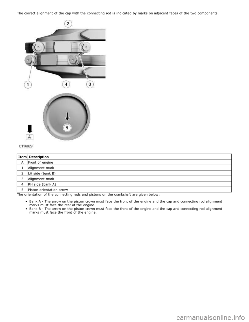
A Front of engine 1 Alignment mark 2 LH side (bank B) 3 Alignment mark 4 RH side (bank A) 5 Piston orientation arrow The orientation of the connecting rods and pistons on the crankshaft are given below:
Bank A - The arrow on the piston crown must face the front of the engine and the cap and connecting rod alignment
marks must face the rear of the engine.
Bank B - The arrow on the piston crown must face the front of the engine and the cap and connecting rod alignment
marks must face the front of the engine.
Page 858 of 3039
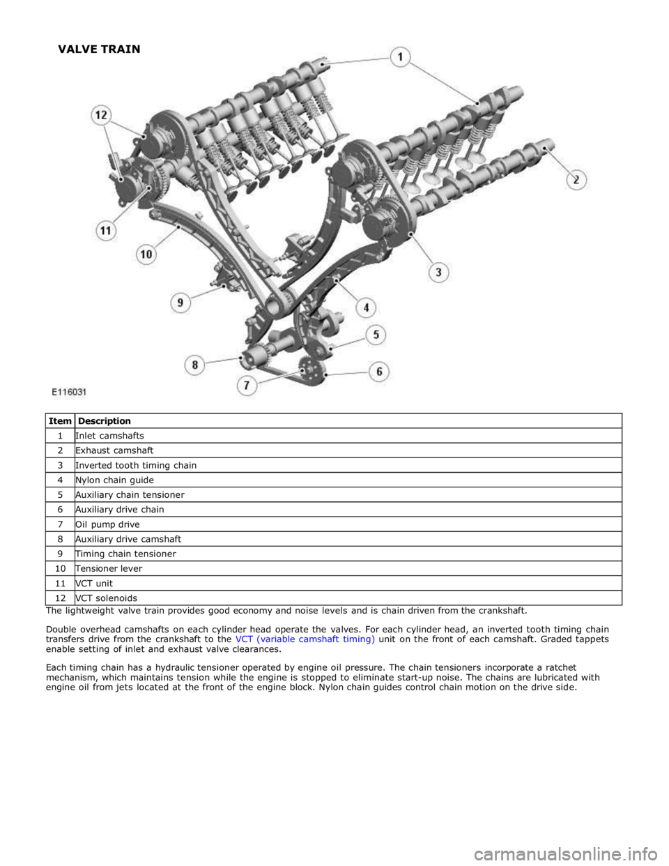
1 Inlet camshafts 2 Exhaust camshaft 3 Inverted tooth timing chain 4 Nylon chain guide 5 Auxiliary chain tensioner 6 Auxiliary drive chain 7 Oil pump drive 8 Auxiliary drive camshaft 9 Timing chain tensioner 10 Tensioner lever 11 VCT unit 12 VCT solenoids The lightweight valve train provides good economy and noise levels and is chain driven from the crankshaft.
Double overhead camshafts on each cylinder head operate the valves. For each cylinder head, an inverted tooth timing chain
transfers drive from the crankshaft to the VCT (variable camshaft timing) unit on the front of each camshaft. Graded tappets
enable setting of inlet and exhaust valve clearances.
Each timing chain has a hydraulic tensioner operated by engine oil pressure. The chain tensioners incorporate a ratchet
mechanism, which maintains tension while the engine is stopped to eliminate start-up noise. The chains are lubricated with
engine oil from jets located at the front of the engine block. Nylon chain guides control chain motion on the drive side. VALVE TRAIN