Engine JAGUAR XFR 2010 1.G Owners Manual
[x] Cancel search | Manufacturer: JAGUAR, Model Year: 2010, Model line: XFR, Model: JAGUAR XFR 2010 1.GPages: 3039, PDF Size: 58.49 MB
Page 692 of 3039
Published: 11-May-2011
Anti-Lock Control - Stability Assist - Anti-Lock Control - Stability Assist - Overview
Description and Operation
Overview
The ABS (anti-lock brake system) and DSC (dynamic stability control) system features a Bosch modulator, which is an
integrated four-channel HCU (hydraulic control unit) and ABS module. The unit is located in the rear of the engine compartment on the passenger side, and is installed in the brake hydraulic circuit between the brake master cylinder and the four brake
calipers.
The ABS module is connected to the high speed CAN (controller area network) bus, and actively interacts with other vehicle system control modules and associated sensors to receive and transmit current vehicle operating information.
When required, the ABS module will actively intervene and operate the HCU during braking or vehicle maneuvers to correct the vehicle attitude, stability, traction or speed. During incidents of vehicle correction, the ABS module may also request the ECM (engine control module) to control engine power in order to further stabilize and correct the vehicle.
To provide full system functionality, the ABS and DSC system comprise the following components: DSC switch.
Four wheel speed sensors.
Steering angle sensor.
Yaw rate and lateral acceleration sensor.
Stoplamp switch.
Instrument cluster indicator lamps.
Integrated ABS module and HCU. Brake booster vacuum sensor (3.0L vehicles only).
Two variants of ABS module are available, Bosch ESP®8.1 and Bosch ESP®plus8.1. The Bosch ESP®plus8.1 system is fitted to vehicles with ACC (adaptive cruise control) and incorporates a new feature to Jaguar known as 'electronic brake prefill'.
Electronic brake prefill, senses any rapid throttle lift off, activating a small brake hydraulic pressure build-up of approximately 3
to 5 bar (43.5 to 72.5 lbf/in²) in anticipation of the brakes being applied. This application produces a quicker brake pedal
response and consequently slightly shorter stopping distances. When the ECM detects rapid throttle lift off it signals the ABS module which controls the HCU to apply a low brake pressure to assist in a quicker brake application.
NOTE: All vehicles with ACC are supported by the Bosch ESP®plus8.1 system.
The ABS provides the following brake functions that are designed to assist the vehicle or aid the driver: ABS. DSC, including Trac DSC.
CBC (corner brake control).
EBD (electronic brake force distribution).
ETC (electronic traction control).
EBA (emergency brake assist).
EDC (engine drag-torque control).
Understeer control.
Electronic brake prefill (vehicles with ACC only).
Brake vacuum assist (3.0L vehicles only).
All the brake functions listed are automatically active when the ignition is in power mode and the engine is running. The DSC
system can be selected to off using the DSC switch.
WARNING: Although the vehicle is fitted with DSC, it remains the drivers responsibility to drive safely according to the
prevailing conditions.
Page 693 of 3039
Published: 11-May-2011
Anti-Lock Control - Stability Assist - Anti-Lock Control - Stability Assist - System Operation and Component Description
Description and Operation
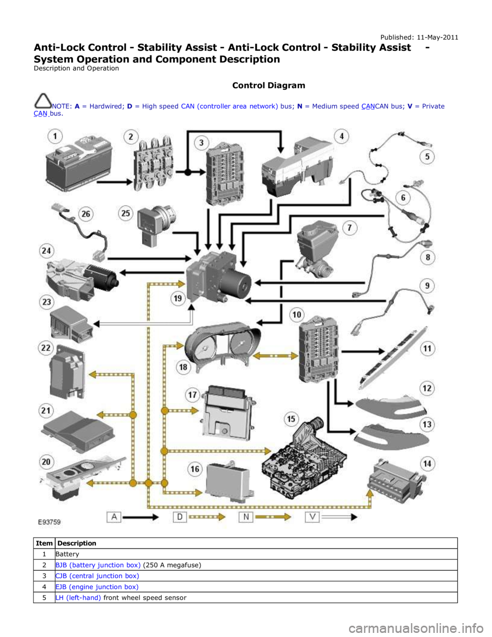
Control Diagram
NOTE: A = Hardwired; D = High speed CAN (controller area network) bus; N = Medium speed CANCAN bus; V = Private CAN bus.
Item Description 1 Battery 2 BJB (battery junction box) (250 A megafuse) 3 CJB (central junction box) 4 EJB (engine junction box) 5 LH (left-hand) front wheel speed sensor
Page 694 of 3039
7 Brake fluid level switch 8 LH rear wheel speed sensor 9 RH rear wheel speed sensor 10 RJB (rear junction box) 11 High mounted stop lamp 12 LH stop lamp 13 RH stop lamp 14 Diagnostic socket 15 TCM (transmission control module) 16 Electronic parking brake module 17 ECM (engine control module) 18 Instrument cluster 19 ABS (anti-lock brake system) module 20 JaguarDrive selector module 21 Adaptive damping control module 22 Adaptive speed control module 23 Yaw rate and lateral acceleration sensor 24 Roof opening panel motor/module 25 Brake booster vacuum sensor (3.0L vehicles only) 26 Steering angle sensor
Anti-Lock Brake System System Operation
ABS controls the speed of all road wheels to ensure optimum wheel slip when braking at the adhesion limit. The wheels are prevented from locking to retain effective steering control of the vehicle.
The brake pressures are modulated separately for each wheel. Rear brake pressures are controlled to maintain rear stability on
split friction surfaces.
Dynamic Stability Control
DSC (dynamic stability control) uses brakes and powertrain torque control to assist in maintaining the yaw stability of the
vehicle. While the ignition is energized the DSC function is permanently enabled, unless selected off using the DSC switch.
DSC enhances driving safety in abrupt maneuvers and in under-steer or over-steer situations that may occur in a bend. The
ABS module monitors the yaw rate and lateral acceleration of the vehicle, steering input and individual wheel speeds, then selectively applies individual brakes and signals for powertrain torque adjustments to reduce under-steer or over-steer
conditions.
In general:
In an under-steer situation the inner wheels are braked to counteract the yaw movement towards the outer edge of the
bend.
In an over-steer situation the outer wheels are braked to prevent the rear end of the vehicle from pushing towards the
outer edge of the bend.
The ABS module monitors the tracking stability of the vehicle using inputs from the wheel speed sensors, the steering angle sensor, and the yaw rate and lateral acceleration sensor. The tracking stability is compared with stored target data. Whenever
the tracking stability deviates from the target data, the ABS module intervenes by applying the appropriate control strategy. The following interactions occur in an intervention situation:
High speed CAN signal to the ECM, to reduce engine torque. Application of braking to the appropriate corner of the vehicle.
Trac DSC
TracDSC is an alternative setting of DSC with reduced system interventions. With TracDSC engaged, traction may be somewhat
increased, although stability may be reduced compared to normal DSC. TracDSC is intended for use only on dry tarmac, by
suitably experienced drivers and should not be selected for other surfaces or by drivers with insufficient skill and training to
operate the vehicle safely with the TracDSC function engaged.
The less restrictive TracDSC setting may be preferred, for example, by expert drivers engaged in high performance driving on
dry Tarmac surfaces such as tracks and circuits.
Switching between DSC and Trac DSC:
Page 695 of 3039
Press and hold the DSC switch for less than 10 seconds.
The message center will temporarily display either Trac DSC or DSC ON.
The warning indicator in the instrument panel will illuminate while Trac DSC is selected.
The warning indicator will flash when DSC or Trac DSC is active.
NOTE: If cruise control is engaged, it will automatically disengage if DSC activates.
Refer to: Speed Control (310-03 Speed Control - 2.7L V6 - TdV6, Description and Operation).
Corner Brake Control
CBC (corner brake control) influences the brake pressures, below and within DSC and ABS thresholds, to counteract the yawing moment produced when braking in a corner. CBC produces a correction torque by limiting the brake pressure on one side of the
vehicle.
Electronic Brake Force Distribution
EBD (electronic brake force distribution) limits the brake pressure applied to the rear wheels. When the brakes are applied, the
weight of the vehicle transfers forwards, reducing the ability of the rear wheels to transfer braking effort to the road surface.
This may cause the rear wheels to slip and make the vehicle unstable.
EBD uses the ABS braking hardware to automatically optimize the pressure to the rear brakes, below the point where ABS is normally invoked.
NOTE: Only the rear brakes are controlled by the EBD function.
Electronic Traction Control
ETC (electronic traction control) attempts to optimize forward traction by reducing engine torque, or by applying the brake of a
spinning wheel until traction is regained.
ETC is activated if an individual wheel speed is above that of the vehicle reference speed (positive slip) and the brake pedal is
not pressed. The brake is applied to the spinning wheel, allowing the excess torque to be transmitted to the non-spinning
wheel through the drive line. If necessary, the ABS module also sends a high speed CAN bus message to the ECM to request a reduction in engine torque.
When the DSC function is selected off using the DSC switch, the braking and engine torque reduction features are both
disabled, except when the JaguarDrive control is in winter mode. When the JaguarDrive control is in winter mode, selecting the
DSC function off retains the braking and engine torque reduction features, but reduces intervention levels compared to DSC
and Trac DSC modes.
Emergency Brake Assist
EBA (emergency brake assist) assists the driver in emergency braking situations by automatically increasing the applied
braking effort. The ABS module invokes EBA when: The brake pedal is rapidly pressed.
The brake pedal is pressed hard enough to bring the front brakes into ABS operation.
When the brake pedal is rapidly pressed, the ABS module increases the hydraulic pressure to all of the brakes until the threshold for ABS operation is reached. This action applies the maximum braking effort for the available traction. The ABS module monitors for the sudden application of the brakes, using inputs from the brake pedal switch and from the pressure
sensor within the HCU (hydraulic control unit). With the brake pedal pressed, if the rate of increase of hydraulic pressure
exceeds the predetermined limit, the ABS module invokes emergency braking.
When the brake pedal is pressed hard enough to bring the front brakes into ABS operation, the ABS module increases the hydraulic pressure to the rear brakes up to the ABS threshold.
EBA operation continues until the driver releases the brake pedal, sufficiently for the hydraulic pressure in the HCU to drop below a threshold value stored in the ABS module.
Engine Drag-Torque Control
EDC (engine drag-torque control) prevents wheel slip caused by any of the following: A
sudden decrease in engine torque when the accelerator is suddenly released.
A downshift using the Jaguar sequential shift function on automatic transmission vehicles.
When the ABS module detects the onset of wheel slip without the brakes being applied, the ABS module signals the ECM via the high speed CAN bus to request a momentary increase in engine torque.
Understeer Control
Understeer Logic Control is a proactive system which monitors the vehicle for understeer by comparing signals from the yaw
rate and lateral acceleration sensor with signals from the steering angle sensor and wheel speed sensors. www.JagDocs.com
Page 696 of 3039
a decrease in engine torque. At the same time the ABS module will control the HCU to apply brake pressure to the relevant wheels to correct the understeer.
Electronic Brake Prefill (Vehicles With ACC Only)
Electronic brake prefill (Bosch ESP®plus8.1), senses any rapid throttle lift off, activating a small brake hydraulic pressure
build-up of approximately 3 to 5 bar (43.5 to 72.5 lbf/in²) in anticipation of the brakes being applied.
This application produces a quicker brake pedal response and consequently slightly shorter stopping distances. The system
supports vehicles with ACC (adaptive cruise control).
When the ABS module detects rapid throttle lift off (from the signals received from the ECM over the high speed CAN bus), it controls the HCU to apply a low brake pressure to assist in a quicker brake application.
Brake Vacuum Assist (3.0L Vehicles Only)
Operation of Brake Vacuum Assist generally occurs at the beginning of an ignition cycle when brake booster vacuum levels are
low; refer to Brake Booster Vacuum sensor, below.
Brake vacuum assist operation will be recognized by the driver experiencing a vibrating brake pedal and slight modulator noise.
This will be similar to that experienced when ABS system is operating.
As the engine warms up, Brake Vacuum Assist operation will become less frequent. However, it can be become more active
when vacuum levels are low due to driving at high-altitudes, or during frequent heavy-braking.
Noise levels during Brake Vacuum Assist may vary with initial system activity being the loudest observed. In some
circumstances initial activity may be interpreted as a 'thump' noise, particularly if there is no immediate and significant Brake
Vacuum Assist functionality.
In this circumstance system behavior is normal and should not be a cause for fault investigation.
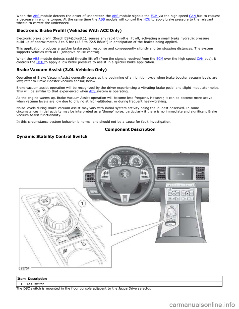
Dynamic Stability Control Switch Component Description
Item Description 1 DSC switch The DSC switch is mounted in the floor console adjacent to the JaguarDrive selector.
Page 697 of 3039
DSC becomes active whenever the engine is running. A momentary press of the switch allows the driver to toggle between the
standard DSC settings and the optimized 'Trac DSC' settings. The message 'Trac DSC' or 'DSC on' will temporarily be displayed
in the instrument cluster message center. The amber DSC warning indicator in the instrument cluster remains illuminated while
'Trac DSC' is selected.
The DSC can be switched off by pressing and holding the switch for more than 10 seconds.
In each case the message 'DSC OFF' will be displayed in the instrument cluster message center to confirm DSC has been
switched off. The amber DSC warning indicator in the instrument cluster will remain illuminated. The system can be switched
back on again by simply pressing and releasing the switch. The message 'DSC ON' will then temporarily appear in the
instrument cluster message center to confirm the system is on.
NOTE: Switch requests may be delayed if the switch is pressed while a DSC operation is taking place. The switch request
will be displayed in the instrument cluster but the ABS module will not initiate any stability changes until it is safe to do so.
If a fault is detected with the DSC switch, the ABS module defaults to the 'DSC ON' setting and any switch requests are ignored.
WARNING: It is recommended that when using snow chains, Trac DSC is switched off and JaguarDrive control winter mode
is selected.
Wheel Speed Sensors
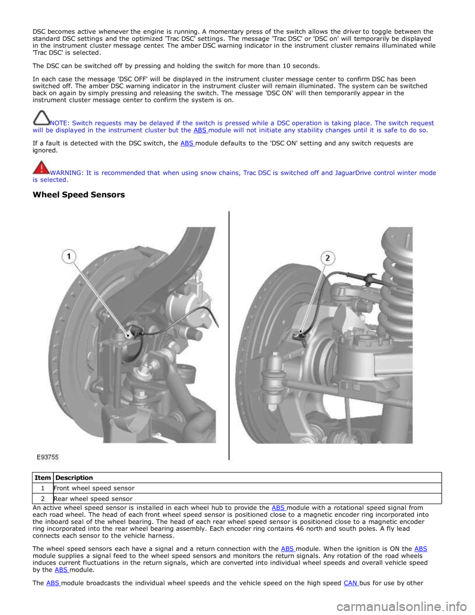
Item Description 1 Front wheel speed sensor 2 Rear wheel speed sensor An active wheel speed sensor is installed in each wheel hub to provide the ABS module with a rotational speed signal from each road wheel. The head of each front wheel speed sensor is positioned close to a magnetic encoder ring incorporated into
the inboard seal of the wheel bearing. The head of each rear wheel speed sensor is positioned close to a magnetic encoder
ring incorporated into the rear wheel bearing assembly. Each encoder ring contains 46 north and south poles. A fly lead
connects each sensor to the vehicle harness.
The wheel speed sensors each have a signal and a return connection with the ABS module. When the ignition is ON the ABS module supplies a signal feed to the wheel speed sensors and monitors the return signals. Any rotation of the road wheels
induces current fluctuations in the return signals, which are converted into individual wheel speeds and overall vehicle speed
by the ABS module. The ABS module broadcasts the individual wheel speeds and the vehicle speed on the high speed CAN bus for use by other
Page 702 of 3039
ABS Module
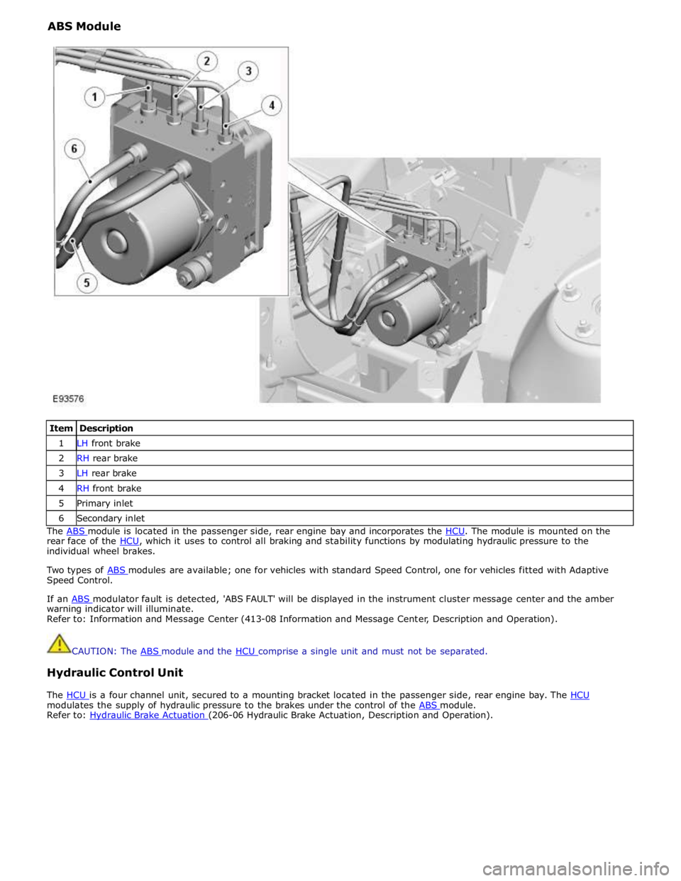
Item Description 1 LH front brake 2 RH rear brake 3 LH rear brake 4 RH front brake 5 Primary inlet 6 Secondary inlet The ABS module is located in the passenger side, rear engine bay and incorporates the HCU. The module is mounted on the rear face of the HCU, which it uses to control all braking and stability functions by modulating hydraulic pressure to the individual wheel brakes.
Two types of ABS modules are available; one for vehicles with standard Speed Control, one for vehicles fitted with Adaptive Speed Control.
If an ABS modulator fault is detected, 'ABS FAULT' will be displayed in the instrument cluster message center and the amber warning indicator will illuminate.
Refer to: Information and Message Center (413-08 Information and Message Center, Description and Operation).
CAUTION: The ABS module and the HCU comprise a single unit and must not be separated.
Hydraulic Control Unit
The HCU is a four channel unit, secured to a mounting bracket located in the passenger side, rear engine bay. The HCU modulates the supply of hydraulic pressure to the brakes under the control of the ABS module. Refer to: Hydraulic Brake Actuation (206-06 Hydraulic Brake Actuation, Description and Operation).
Page 724 of 3039
2. Free play should be between 0 and 6 mm (0 and 0.24 in) at the steering wheel rim. If the free play exceeds this limit,
either the ball joints are worn, the lower steering column joints are worn or the backlash of the steering gear is
excessive.
CAUTION: DO NOT attempt to adjust the steering gear yoke. Failure to follow this instruction will invalidate the steering
gear warranty.
3. The backlash of the steering gear cannot be adjusted, install a new steering gear if excessive backlash is diagnosed.
4. Grasp the steering wheel firmly and move it up and down and to the left and right without turning the wheel to check
for column bearing wear, steering wheel or steering column.
Power Steering Fluid Condition Check
1. Run the engine for 2 minutes.
2. Check the power steering fluid system level.
3. Observe the color and the odor. The color under normal circumstances should be dark reddish, not brown or black.
4. Using a suitable clean syringe extract a suitable amount of fluid from the reservoir.
5. Allow the fluid to drip onto a facial tissue and examine the stain.
6. If evidence of solid material is found, the power steering fluid system should be drained for further inspection.
7. If fluid contamination or steering component failure is confirmed by the sediment in the power steering fluid system,
refer to Steering Fault Diagnosis by Symptom Charts in this section.
Power Steering Pressure Test
Test Equipment
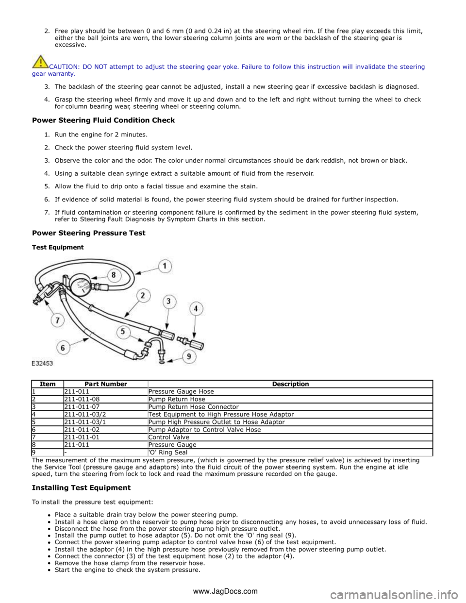
Item Part Number Description 1 211-011 Pressure Gauge Hose 2 211-011-08 Pump Return Hose 3 211-011-07 Pump Return Hose Connector 4 211-011-03/2 Test Equipment to High Pressure Hose Adaptor 5 211-011-03/1 Pump High Pressure Outlet to Hose Adaptor 6 211-011-02 Pump Adaptor to Control Valve Hose 7 211-011-01 Control Valve 8 211-011 Pressure Gauge 9 - 'O' Ring Seal The measurement of the maximum system pressure, (which is governed by the pressure relief valve) is achieved by inserting
the Service Tool (pressure gauge and adaptors) into the fluid circuit of the power steering system. Run the engine at idle
speed, turn the steering from lock to lock and read the maximum pressure recorded on the gauge.
Installing Test Equipment
To install the pressure test equipment:
Place a suitable drain tray below the power steering pump.
Install a hose clamp on the reservoir to pump hose prior to disconnecting any hoses, to avoid unnecessary loss of fluid.
Disconnect the hose from the power steering pump high pressure outlet.
Install the pump outlet to hose adaptor (5). Do not omit the 'O' ring seal (9).
Connect the power steering pump adaptor to control valve hose (6) of the test equipment.
Install the adaptor (4) in the high pressure hose previously removed from the power steering pump outlet.
Connect the connector (3) of the test equipment hose (2) to the adaptor (4).
Remove the hose clamp from the reservoir hose.
Start the engine to check the system pressure. www.JagDocs.com
Page 725 of 3039
With the control valve (7) OPEN and the engine idling, the following system pressures may be checked:
During turning when static (dry parking pressure).
When the steering is held on full lock (maximum system pressure or pressure relief).
With the steering at rest (idle pressure or back pressure).
CAUTIONS:
To avoid excessive heating of the power steering pump when checking the pressure, do not close the valve for more than
5 seconds maximum.
When checking the pump pressure DO NOT drive the vehicle with the test equipment installed.
With the control valve (7) CLOSED the power steering pump maximum output pressure can be checked.
Removing Test Equipment
To remove the test equipment:
Install a hose clamp on the reservoir to power steering pump hose.
Removing the test equipment is a reversal of the installation instructions.
Install a new 'O' ring seal (9) to the power steering pump high pressure outlet to hose connection.
Install the original hose to the power steering pump.
Remove the clamp from the reservoir to the power steering pump hose.
Top-up the reservoir fluid.
Bleed the power steering system.
REFER to: Power Steering System Bleeding (211-00 Steering System - General Information, General Procedures).
Description of Terms General Steering System Noises
Boom
Rhythmic sound like a drum roll or distant thunder. May cause pressure on the ear drum.
Buzz
Low-pitched sound, like a bee. Usually associated with vibrations.
Chatter
Rapidly repeating metallic sound.
Chuckle
Rapid noise that sounds like a stick against the spokes of a spinning bicycle wheel.
Chirp
High pitched rapidly repeating sound, like chirping birds.
Click
Light sound, like a ball point pen being clicked.
Click/Thump
Heavy metal-to-metal sound, like a hammer striking steel.
Grind
Abrasive sound, like a grinding wheel or sandpaper rubbing against wood.
Groan/Moan
Continuous, low-pitched humming sound.
Groan/Howl
Low, guttural sound, like an angry dog.
Hiss
Continuous sound like air escaping from a tire valve.
Page 727 of 3039
between moving components such as the steering wheel to steering column shroud.
Grunt (Squawk/Whoop)
Grunt is a 'honking' sound elicited when coming off one of the steering stops. Grunt is generally excited during parking
manoeuvres with a low to medium speed steering input.
Hiss (Swish)
Hiss or Valve Hiss is a high-frequency sound coming from the steering gear when the system is loaded. It is a rushing or
'swish' noise that doesn't change frequency with RPM. Hiss is the general noise generated by the flow of hydraulic fluid through
restrictions in the steering system. Restrictions include the rotary steering valve, power steering tubes, connectors, tuning
orifices, etc. Hiss can be air-borne and structure-borne, but the structure-borne path through the steering intermediate shaft is
usually dominant.
Moan (Groan)
Moan is the general structure-borne noise of the steering system. Moan is primarily transmitted to the driver via the body
structure through the pump mount, engine mounts, power steering lines and power steering brackets. On some vehicles, moan
is a loud humming noise, often present when the wheel is turned and the system is loaded. It may change frequency with
engine RPM and if the system is loaded or unloaded.
Steering Gear Knock (Steering Gear Slap)
CAUTION: DO NOT attempt to adjust the steering gear yoke. Failure to follow this instruction will invalidate the steering
gear warranty.
Steering gear knock is a rattle sound and steering wheel vibration caused by separation of the steering gear and pinion while
driving over bumps. It is a structure-borne noise transmitted through the intermediate shaft and column. Steering gear knock
can also be heard as a 'thump' or impact noise that occurs with the vehicle stationary when the steering wheel is released
from a loaded position and allowed to return to rest. Noise occurs with the engine on or off.
Rattles
Rattles are noises caused by knocking or hitting of components in the steering system. Steering rattles can occur in the engine
compartment, the suspension, or the passenger compartment. Rattles can be caused by loose components, movable and
flexible components, and improper clearances.
Squeaks/Scrapes
Squeaks/Scrapes are noises due to friction or component rubbing anywhere in the steering system. Squeaks/Scrapes have
appeared in steering linkages and joints, in column components and in column and steering wheel trim.
Weep
Weep is an air-borne noise, occasionally generated when turning the steering across lock at a constant rate. When present on
a vehicle the noise, once initiated can often be maintained across a large proportion of the available steering movement.
Whistle
Whistle is similar to hiss but is louder and of a higher frequency. It is also more of a pure tone noise than hiss. Whistle is
air-borne and is generated by a high flow rate of hydraulic fluid through a small restriction.
Zip
Zip noise is the air-borne noise generated by power steering pump cavitation when power steering fluid does not flow freely
through the suction hose from the reservoir to the pump. Zip primarily occurs during cold weather at start-up.
Steering System Vibrations and Harshness
Buzz
Buzz is a tactile rotary vibration felt in the steering wheel when steering inputs are slow. Buzz can also be called a grinding
feel and it is closely related to grunt and is caused by high system gain with low damping. Buzz is generally excited during
parking manoeuvres with low to medium speed steering input.
Buzz (Electrical)
A different steering buzz can be caused by pulse width modulated (PWM) electric actuators used in variable assist steering
systems. This buzz is felt by turning the ignition key to run without starting the engine and holding onto the steering wheel.
In extreme cases, the buzz can be felt with the engine running also.
Column/Steering Wheel Shake
Column shake is a low frequency vertical vibration excited by primary engine vibrations.
Nibble (Shimmy)