Engine JAGUAR XFR 2010 1.G Workshop Manual
[x] Cancel search | Manufacturer: JAGUAR, Model Year: 2010, Model line: XFR, Model: JAGUAR XFR 2010 1.GPages: 3039, PDF Size: 58.49 MB
Page 859 of 3039
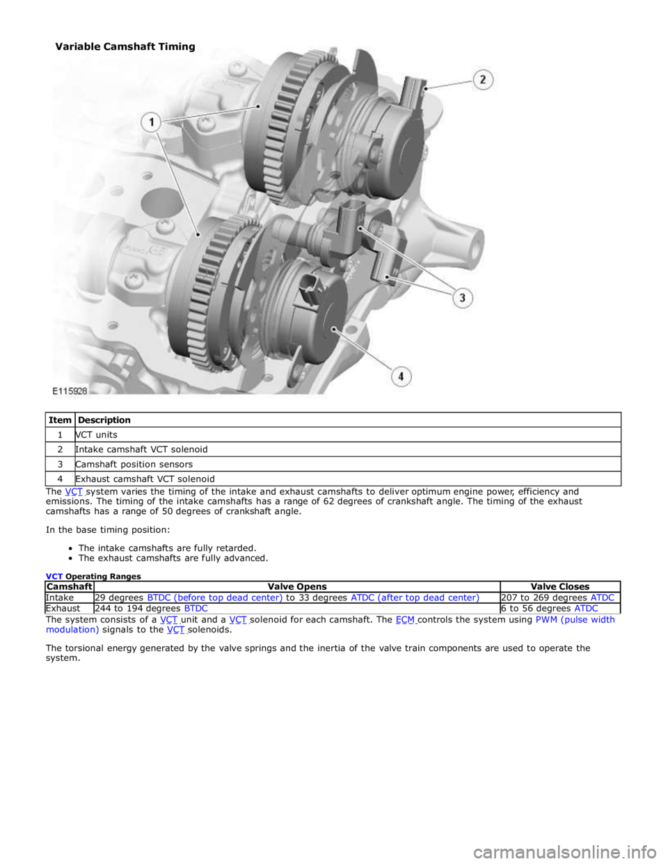
1 VCT units 2 Intake camshaft VCT solenoid 3 Camshaft position sensors 4 Exhaust camshaft VCT solenoid The VCT system varies the timing of the intake and exhaust camshafts to deliver optimum engine power, efficiency and emissions. The timing of the intake camshafts has a range of 62 degrees of crankshaft angle. The timing of the exhaust
camshafts has a range of 50 degrees of crankshaft angle.
In the base timing position:
The intake camshafts are fully retarded.
The exhaust camshafts are fully advanced.
VCT Operating Ranges
Camshaft Valve Opens Valve Closes Intake 29 degrees BTDC (before top dead center) to 33 degrees ATDC (after top dead center) 207 to 269 degrees ATDC Exhaust 244 to 194 degrees BTDC 6 to 56 degrees ATDC The system consists of a VCT unit and a VCT solenoid for each camshaft. The ECM controls the system using PWM (pulse width modulation) signals to the VCT solenoids.
The torsional energy generated by the valve springs and the inertia of the valve train components are used to operate the
system. Variable Camshaft Timing
Page 861 of 3039
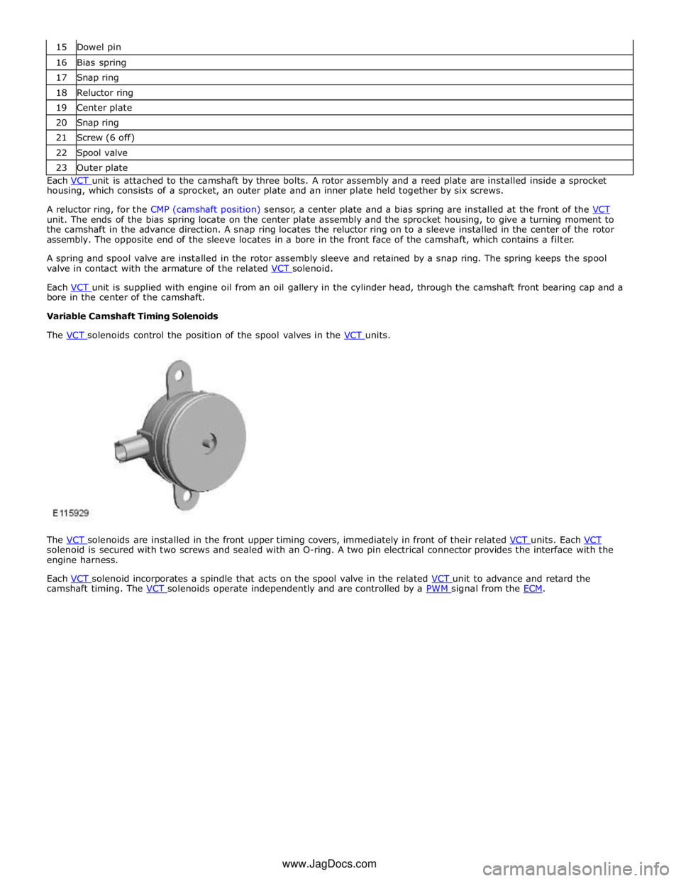
16 Bias spring 17 Snap ring 18 Reluctor ring 19 Center plate 20 Snap ring 21 Screw (6 off) 22 Spool valve 23 Outer plate Each VCT unit is attached to the camshaft by three bolts. A rotor assembly and a reed plate are installed inside a sprocket housing, which consists of a sprocket, an outer plate and an inner plate held together by six screws.
A reluctor ring, for the CMP (camshaft position) sensor, a center plate and a bias spring are installed at the front of the VCT unit. The ends of the bias spring locate on the center plate assembly and the sprocket housing, to give a turning moment to
the camshaft in the advance direction. A snap ring locates the reluctor ring on to a sleeve installed in the center of the rotor
assembly. The opposite end of the sleeve locates in a bore in the front face of the camshaft, which contains a filter.
A spring and spool valve are installed in the rotor assembly sleeve and retained by a snap ring. The spring keeps the spool
valve in contact with the armature of the related VCT solenoid.
Each VCT unit is supplied with engine oil from an oil gallery in the cylinder head, through the camshaft front bearing cap and a bore in the center of the camshaft.
Variable Camshaft Timing Solenoids
The VCT solenoids control the position of the spool valves in the VCT units.
The VCT solenoids are installed in the front upper timing covers, immediately in front of their related VCT units. Each VCT solenoid is secured with two screws and sealed with an O-ring. A two pin electrical connector provides the interface with the
engine harness.
Each VCT solenoid incorporates a spindle that acts on the spool valve in the related VCT unit to advance and retard the camshaft timing. The VCT solenoids operate independently and are controlled by a PWM signal from the ECM. www.JagDocs.com
Page 862 of 3039
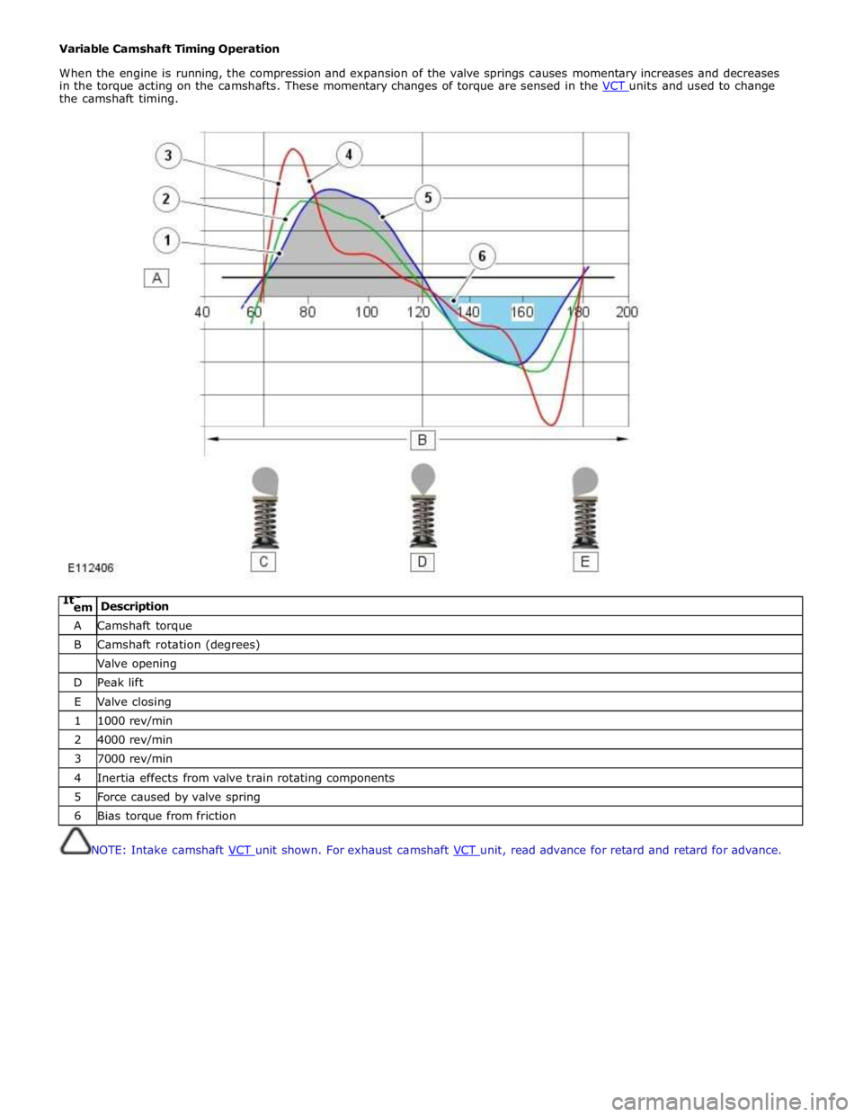
Variable Camshaft Timing Operation
When the engine is running, the compression and expansion of the valve springs causes momentary increases and decreases
in the torque acting on the camshafts. These momentary changes of torque are sensed in the VCT units and used to change the camshaft timing.
ItC
em Description A Camshaft torque B Camshaft rotation (degrees) Valve opening D Peak lift E Valve closing 1 1000 rev/min 2 4000 rev/min 3 7000 rev/min 4 Inertia effects from valve train rotating components 5 Force caused by valve spring 6 Bias torque from friction
NOTE: Intake camshaft VCT unit shown. For exhaust camshaft VCT unit, read advance for retard and retard for advance.
Page 863 of 3039

1 Advance chamber 2 Retard chamber 3 Sprocket housing 4 Rotor assembly 5 Lock pin 6 Sleeve 7 Engine oil supply from camshaft 8 Inlet check valve 9 Lock pin drain 10 Spool valve 11 Advance check valve 12 Retard check valve At engine start-up, once the engine oil pressure in the camshaft is sufficient to open the inlet check valve, engine oil flows
across the spool valve, through the advance and retard check valves and into the advance and retard chambers. During the
start cycle, the ECM signals the VCT solenoid to move the spool valve into the sleeve and connect the lock pin to inlet oil
Page 867 of 3039
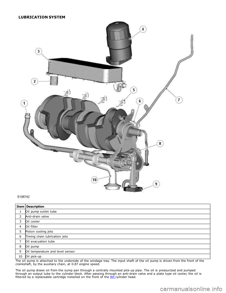
1 Oil pump outlet tube 2 Anti-drain valve 3 Oil cooler 4 Oil filter 5 Piston cooling jets 6 Timing chain lubrication jets 7 Oil evacuation tube 8 Oil pump 9 Oil temperature and level sensor 10 Oil pick-up The oil pump is attached to the underside of the windage tray. The input shaft of the oil pump is driven from the front of the
crankshaft, by the auxiliary chain, at 0.87 engine speed.
The oil pump draws oil from the sump pan through a centrally mounted pick-up pipe. The oil is pressurized and pumped
through an output tube to the cylinder block. After passing through an anti-drain valve and a plate type oil cooler, the oil is
filtered by a replaceable cartridge installed on the front of the RH cylinder head. LUBRICATION SYSTEM
Page 868 of 3039
cooling jets and the timing chain lubrication jets.
The oil returns to the oil pan under gravity. Large drain holes through the cylinder heads and cylinder block ensure the rapid
return of the oil to the sump pan. System replenishment is through the oil filler cap on the LH cylinder head cover.
An oil evacuation tube is installed to allow oil to be drawn from the sump pan. The upper end of the oil evacuation tube is
located under the oil filler cap.
An oil drain plug is installed in the RH side of the sump pan.
Oil Pump Nominal Operating Pressures
Engine Speed, rev/min Temperature, °C (°F) Pressure, bar (lbf/in2
) Idle 20 (68) 2.0 (29.0) 1500 20 (68) 6.0 (87.0) 3000 40 (104) 6.2 (90.0) 3000 110 (230) 5.0 (72.5) 3000 130 (266) 4.0 (58.0) Oil Level Monitoring
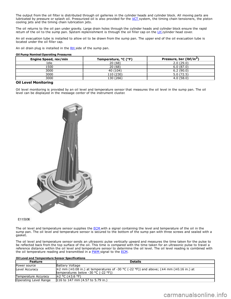
Oil level monitoring is provided by an oil level and temperature sensor that measures the oil level in the sump pan. The oil
level can be displayed in the message center of the instrument cluster.
The oil level and temperature sensor supplies the ECM with a signal containing the level and temperature of the oil in the sump pan. The oil level and temperature sensor is secured to the bottom of the sump pan with three screws and sealed with a
gasket.
The oil level and temperature sensor sends an ultrasonic pulse vertically upward and measures the time taken for the pulse to
be reflected back from the top surface of the oil. This time is compared with the time taken for an ultrasonic pulse to travel a
reference distance within the oil level and temperature sensor to determine the oil level. The oil level reading is combined with
the oil temperature reading and transmitted in a PWM signal to the ECM.
Oil Level and Temperature Sensor Specifications
Feature Details Power source Battery Voltage Level Accuracy ±2 mm (±0.08 in.) at temperatures of -30 °C (-22 °F)) and above; (±4 mm (±0.16 in.) at
temperatures below -30 °C (-22 °F)) Temperature Accuracy ±2 °C (±3.6 °F) Operating Level Range 116 to 147 mm (4.57 to 5.79 in.)
Page 869 of 3039
Operating Temperature Range -40 to 160 °C (-40 to 320 °F) Oil Level Check
For additional information, refer to Engine Oil Draining and Filling (303-01A, General Procedures).
For accuracy, oil level checks should be performed with the vehicle on level ground when the oil is hot. The vehicle needs to
stand for approximately 10 minutes, after the engine is switched off, to allow the oil to drain back into the sump pan and the
oil level to stabilize. The oil level system will not give a reading until the oil level has stabilized.
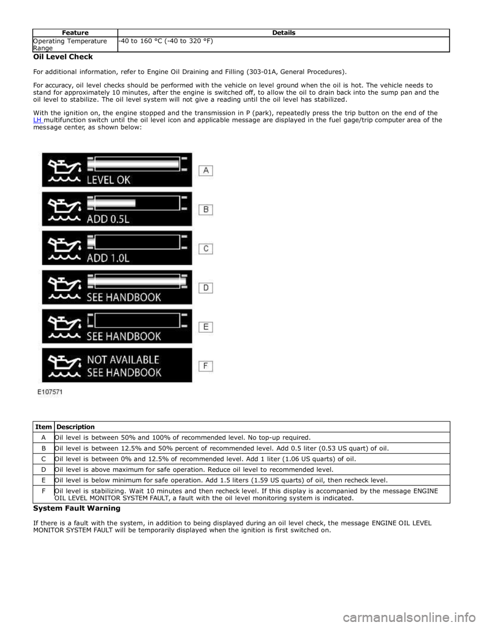
With the ignition on, the engine stopped and the transmission in P (park), repeatedly press the trip button on the end of the
LH multifunction switch until the oil level icon and applicable message are displayed in the fuel gage/trip computer area of the message center, as shown below:
Item Description A Oil level is between 50% and 100% of recommended level. No top-up required. B Oil level is between 12.5% and 50% percent of recommended level. Add 0.5 liter (0.53 US quart) of oil. C Oil level is between 0% and 12.5% of recommended level. Add 1 liter (1.06 US quarts) of oil. D Oil level is above maximum for safe operation. Reduce oil level to recommended level. E Oil level is below minimum for safe operation. Add 1.5 liters (1.59 US quarts) of oil, then recheck level. F Oil level is stabilizing. Wait 10 minutes and then recheck level. If this display is accompanied by the message ENGINE OIL LEVEL MONITOR SYSTEM FAULT, a fault with the oil level monitoring system is indicated. System Fault Warning
If there is a fault with the system, in addition to being displayed during an oil level check, the message ENGINE OIL LEVEL
MONITOR SYSTEM FAULT will be temporarily displayed when the ignition is first switched on.
Page 871 of 3039

Engine - V8 S/C 5.0L Petrol - Engine Oil Draining and Filling
General Procedures
Draining Published: 11-May-2011
WARNING: The spilling of hot engine oil is unavoidable during this procedure, care must be taken to prevent scalding.
CAUTION: Correct installation of the oil filler cap can be obtained by tightening the cap until hard stop.
NOTE: Clean the components general area prior to dismantling.
1. CAUTION: Make sure the engine is warm.
Start the engine and allow to run for 10 minutes, stop the engine.
2.
3. Refer to: Engine Cover - V8 5.0L Petrol/V8 S/C 5.0L Petrol (501-05 Interior Trim and Ornamentation, Removal and Installation).
4.
Loosen the element cover 4 complete turns to allow
engine oil to drain from the filter cover.
Make sure that the O-ring seal is exposed.
5. NOTE: Allow 10 minutes for the engine oil to drain from the oil filter
housing. www.JagDocs.com
Page 872 of 3039

6. NOTE: Remove and discard the O-ring seal.
7. Remove and discard the oil filter element.
8. WARNING: Do not work on or under a vehicle supported only by a
jack. Always support the vehicle on safety stands.
Raise and support the vehicle.
9. Refer to: Air Deflector (501-02 Front End Body Panels, Removal and Installation).
10. CAUTIONS:
Be prepared to collect escaping oil.
Allow at least 10 minutes for the engine oil to drain.
NOTE: Discard the sealing washer.
Page 873 of 3039

Filling
1. CAUTION: Make sure that the area around the
component is clean and free of foreign material.
NOTE: Install a new sealing washer.
Torque: 24 Nm
2. Refer to: Air Deflector (501-02 Front End Body Panels, Removal and Installation).
3. NOTE: Install new O-ring seals.
Lubricate the oil filter element O-ring seal with clean
engine oil.
4. CAUTION: Tighten the component finger tight first.
Torque: 25 Nm
5. CAUTION: Make sure that the vehicle is left for 5 minutes from
filling with oil and that the engine oil level is reading at least minimum
(by following Steps 9-13), before starting the engine.
Fill the engine with oil - for filling values on vehicles without
supercharger:
Refer to: Specifications (303-01C Engine - V8 5.0L Petrol, Specifications).
Fill the engine with oil - for filling values on vehicles with
supercharger: