ESP JAGUAR XFR 2010 1.G Workshop Manual
[x] Cancel search | Manufacturer: JAGUAR, Model Year: 2010, Model line: XFR, Model: JAGUAR XFR 2010 1.GPages: 3039, PDF Size: 58.49 MB
Page 2152 of 3039
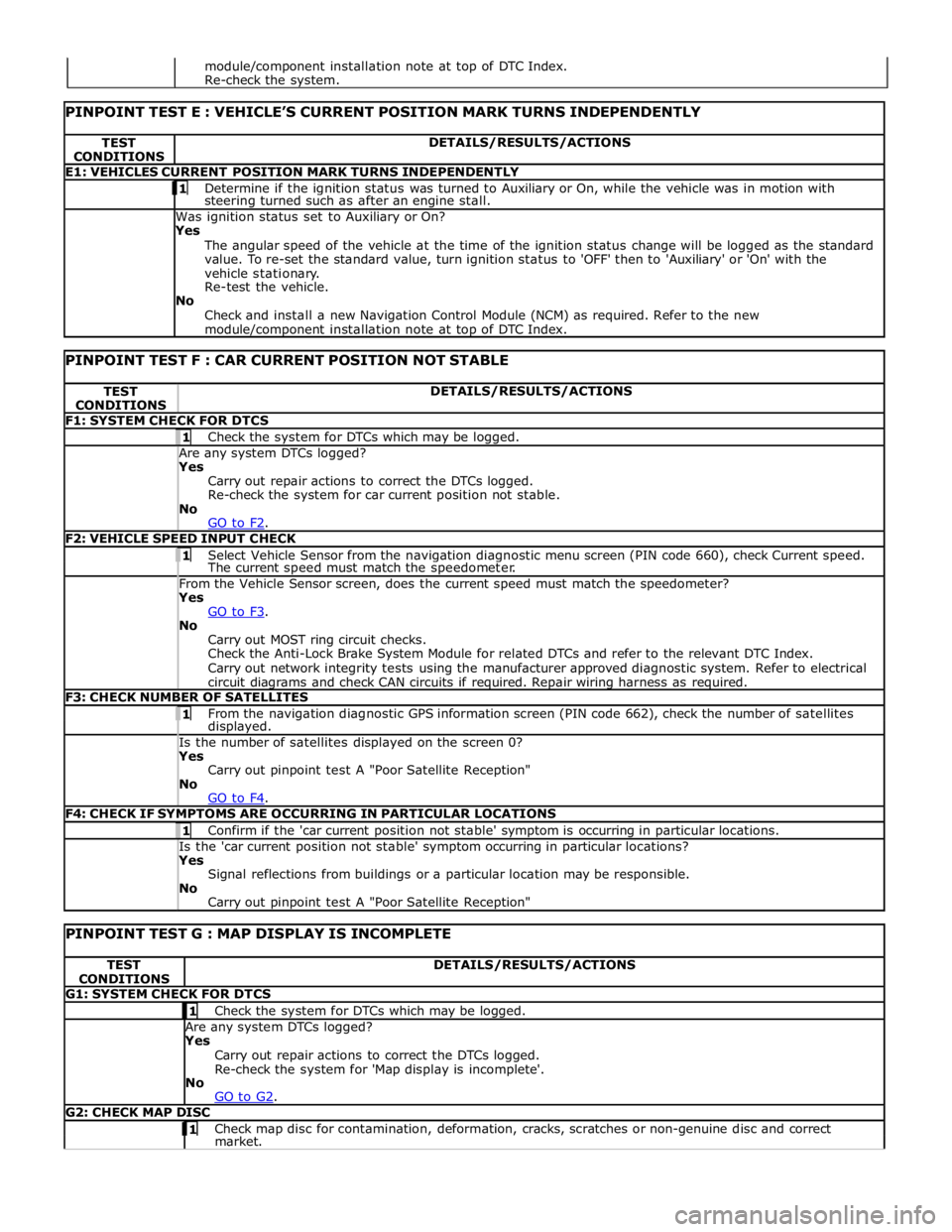
TEST
CONDITIONS DETAILS/RESULTS/ACTIONS E1: VEHICLES CURRENT POSITION MARK TURNS INDEPENDENTLY 1 Determine if the ignition status was turned to Auxiliary or On, while the vehicle was in motion with steering turned such as after an engine stall. Was ignition status set to Auxiliary or On?
Yes
The angular speed of the vehicle at the time of the ignition status change will be logged as the standard
value. To re-set the standard value, turn ignition status to 'OFF' then to 'Auxiliary' or 'On' with the
vehicle stationary.
Re-test the vehicle.
No
Check and install a new Navigation Control Module (NCM) as required. Refer to the new module/component installation note at top of DTC Index.
PINPOINT TEST F : CAR CURRENT POSITION NOT STABLE TEST
CONDITIONS DETAILS/RESULTS/ACTIONS F1: SYSTEM CHECK FOR DTCS 1 Check the system for DTCs which may be logged. Are any system DTCs logged? Yes
Carry out repair actions to correct the DTCs logged.
Re-check the system for car current position not stable.
No
GO to F2. F2: VEHICLE SPEED INPUT CHECK 1 Select Vehicle Sensor from the navigation diagnostic menu screen (PIN code 660), check Current speed. The current speed must match the speedometer. From the Vehicle Sensor screen, does the current speed must match the speedometer? Yes
GO to F3. No
Carry out MOST ring circuit checks.
Check the Anti-Lock Brake System Module for related DTCs and refer to the relevant DTC Index.
Carry out network integrity tests using the manufacturer approved diagnostic system. Refer to electrical
circuit diagrams and check CAN circuits if required. Repair wiring harness as required. F3: CHECK NUMBER OF SATELLITES 1 From the navigation diagnostic GPS information screen (PIN code 662), check the number of satellites displayed. Is the number of satellites displayed on the screen 0? Yes
Carry out pinpoint test A "Poor Satellite Reception"
No
GO to F4. F4: CHECK IF SYMPTOMS ARE OCCURRING IN PARTICULAR LOCATIONS 1 Confirm if the 'car current position not stable' symptom is occurring in particular locations. Is the 'car current position not stable' symptom occurring in particular locations? Yes
Signal reflections from buildings or a particular location may be responsible.
No
Carry out pinpoint test A "Poor Satellite Reception"
PINPOINT TEST G : MAP DISPLAY IS INCOMPLETE TEST
CONDITIONS DETAILS/RESULTS/ACTIONS G1: SYSTEM CHECK FOR DTCS 1 Check the system for DTCs which may be logged. Are any system DTCs logged? Yes
Carry out repair actions to correct the DTCs logged.
Re-check the system for 'Map display is incomplete'.
No
GO to G2. G2: CHECK MAP DISC 1 Check map disc for contamination, deformation, cracks, scratches or non-genuine disc and correct market. module/component installation note at top of DTC Index.
Re-check the system.
Page 2153 of 3039
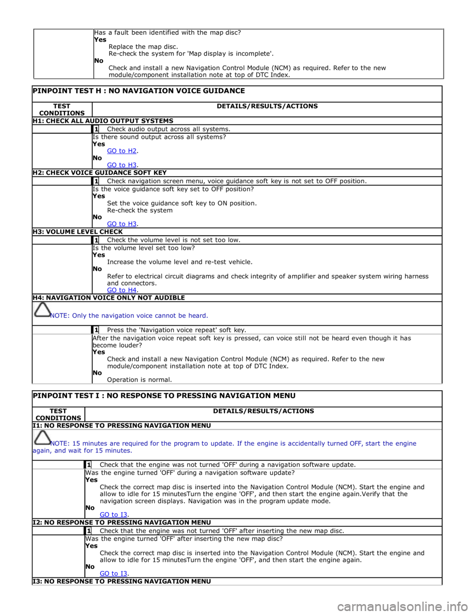
PINPOINT TEST H : NO NAVIGATION VOICE GUIDANCE TEST
CONDITIONS DETAILS/RESULTS/ACTIONS H1: CHECK ALL AUDIO OUTPUT SYSTEMS 1 Check audio output across all systems. Is there sound output across all systems? Yes
GO to H2. No
GO to H3. H2: CHECK VOICE GUIDANCE SOFT KEY 1 Check navigation screen menu, voice guidance soft key is not set to OFF position. Is the voice guidance soft key set to OFF position? Yes
Set the voice guidance soft key to ON position.
Re-check the system
No
GO to H3. H3: VOLUME LEVEL CHECK 1 Check the volume level is not set too low. Is the volume level set too low? Yes
Increase the volume level and re-test vehicle.
No
Refer to electrical circuit diagrams and check integrity of amplifier and speaker system wiring harness
and connectors.
GO to H4. H4: NAVIGATION VOICE ONLY NOT AUDIBLE
NOTE: Only the navigation voice cannot be heard. 1 Press the 'Navigation voice repeat' soft key. After the navigation voice repeat soft key is pressed, can voice still not be heard even though it has
become louder? Yes
Check and install a new Navigation Control Module (NCM) as required. Refer to the new
module/component installation note at top of DTC Index.
No
Operation is normal.
PINPOINT TEST I : NO RESPONSE TO PRESSING NAVIGATION MENU TEST
CONDITIONS DETAILS/RESULTS/ACTIONS I1: NO RESPONSE TO PRESSING NAVIGATION MENU
NOTE: 15 minutes are required for the program to update. If the engine is accidentally turned OFF, start the engine
again, and wait for 15 minutes. 1 Check that the engine was not turned 'OFF' during a navigation software update. Was the engine turned 'OFF' during a navigation software update? Yes
Check the correct map disc is inserted into the Navigation Control Module (NCM). Start the engine and
allow to idle for 15 minutesTurn the engine 'OFF', and then start the engine again.Verify that the
navigation screen displays. Navigation was in the program update mode.
No
GO to I3. I2: NO RESPONSE TO PRESSING NAVIGATION MENU 1 Check that the engine was not turned 'OFF' after inserting the new map disc. Was the engine turned 'OFF' after inserting the new map disc? Yes
Check the correct map disc is inserted into the Navigation Control Module (NCM). Start the engine and
allow to idle for 15 minutesTurn the engine 'OFF', and then start the engine again.
No
GO to I3. I3: NO RESPONSE TO PRESSING NAVIGATION MENU Has a fault been identified with the map disc?
Yes
Replace the map disc.
Re-check the system for 'Map display is incomplete'.
No
Check and install a new Navigation Control Module (NCM) as required. Refer to the new
module/component installation note at top of DTC Index.
Page 2154 of 3039
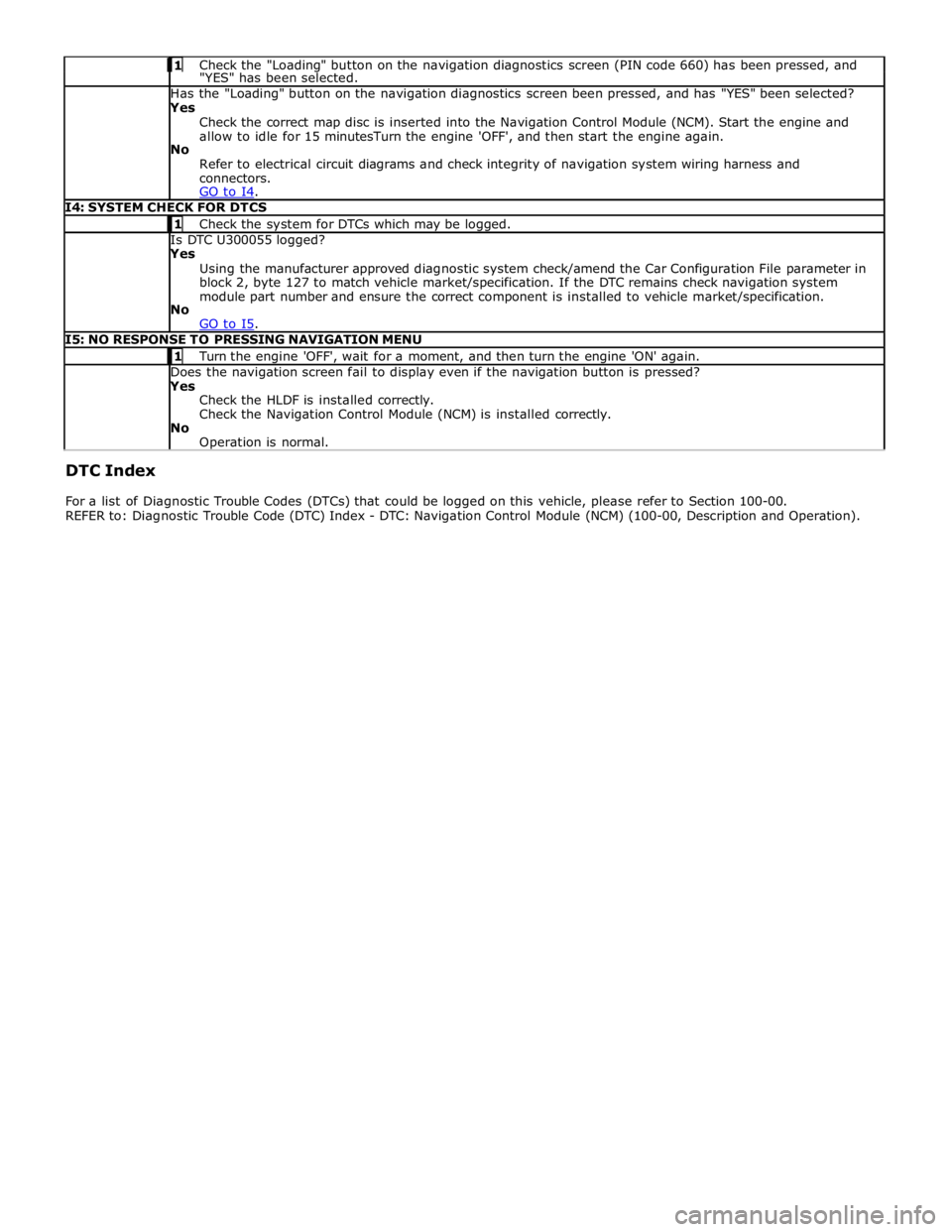
Check the "Loading" button on the navigation diagnostics screen (PIN code 660) has been pressed, and "YES" has been selected. Has the "Loading" button on the navigation diagnostics screen been pressed, and has "YES" been selected? Yes
Check the correct map disc is inserted into the Navigation Control Module (NCM). Start the engine and
allow to idle for 15 minutesTurn the engine 'OFF', and then start the engine again.
No
Refer to electrical circuit diagrams and check integrity of navigation system wiring harness and
connectors.
GO to I4. I4: SYSTEM CHECK FOR DTCS 1 Check the system for DTCs which may be logged. Is DTC U300055 logged? Yes
Using the manufacturer approved diagnostic system check/amend the Car Configuration File parameter in
block 2, byte 127 to match vehicle market/specification. If the DTC remains check navigation system
module part number and ensure the correct component is installed to vehicle market/specification.
No
GO to I5. I5: NO RESPONSE TO PRESSING NAVIGATION MENU 1 Turn the engine 'OFF', wait for a moment, and then turn the engine 'ON' again. Does the navigation screen fail to display even if the navigation button is pressed? Yes
Check the HLDF is installed correctly.
Check the Navigation Control Module (NCM) is installed correctly.
No
Operation is normal. DTC Index
For a list of Diagnostic Trouble Codes (DTCs) that could be logged on this vehicle, please refer to Section 100-00.
REFER to: Diagnostic Trouble Code (DTC) Index - DTC: Navigation Control Module (NCM) (100-00, Description and Operation).
Page 2179 of 3039

DTC Description Possible Cause Action B102B00 Passive Key
Response Error - general
failure Using the manufacturer approved diagnostic system, clear
all passive keys, re-learn all passive keys B10C100
Left Front Unlock Pull
Switch
No subtype information Carry out any pinpoint tests associated with this DTC using
the manufacturer approved diagnostic system B10C124
Left Front Unlock Pull
Switch
Signal stuck high - button
stuck in active position Carry out any pinpoint tests associated with this DTC using
the manufacturer approved diagnostic system. Check for
stuck left front unlock switch. Refer to the electrical circuit
diagrams and check left front unlock switch circuit for short
to ground B10C200
Left Rear Unlock Pull
Switch
No subtype information Carry out any pinpoint tests associated with this DTC using
the manufacturer approved diagnostic system B10C224
Left Rear Unlock Pull
Switch
Signal stuck high - button
stuck in active position Carry out any pinpoint tests associated with this DTC using
the manufacturer approved diagnostic system. Check for
stuck left rear unlock switch. Refer to the electrical circuit
diagrams and check left rear unlock switch circuit for short
to ground B10C300
Right Front Unlock
Pull Switch
No subtype information Carry out any pinpoint tests associated with this DTC using
the manufacturer approved diagnostic system B10C324
Right Front Unlock
Pull Switch
Signal stuck high - button
stuck in active position Carry out any pinpoint tests associated with this DTC using
the manufacturer approved diagnostic system. Check for
stuck right front unlock switch. Refer to the electrical circuit
diagrams and check right front unlock switch circuit for
short to ground B10C400
Right Rear Unlock Pull
Switch
No subtype information Carry out any pinpoint tests associated with this DTC using
the manufacturer approved diagnostic system B10C424
Right Rear Unlock Pull
Switch
Signal stuck high - button
stuck in active position Carry out any pinpoint tests associated with this DTC using
the manufacturer approved diagnostic system. Check for
stuck right rear unlock switch. Refer to the electrical circuit
diagrams and check right front unlock switch circuit for
short to ground B10C524 Trunk Unlock Pull
Switch
Signal stuck high - button
stuck in active position Carry out any pinpoint tests associated with this DTC using
the manufacturer approved diagnostic system. Check for
stuck luggage compartment lid unlock switch. Refer to the
electrical circuit diagrams and check luggage compartment
lid unlock switch circuit for short to ground B10C61F
Exterior Trunk
Antenna
Circuit intermittent -
general electrical error Carry out any pinpoint tests associated with this DTC using
the manufacturer approved diagnostic system. Refer to the
electrical circuit diagrams and check exterior luggage
compartment antenna circuits for short to ground, power, open circuit B10C71F
Interior Trunk
Antenna
Circuit intermittent -
general electrical error Carry out any pinpoint tests associated with this DTC using
the manufacturer approved diagnostic system. Refer to the
electrical circuit diagrams and check interior luggage
compartment antenna circuits for short to ground, power, open circuit B10C81F
Interior Center
Antenna
Circuit intermittent -
general electrical error Carry out any pinpoint tests associated with this DTC using
the manufacturer approved diagnostic system. Refer to the
electrical circuit diagrams and check interior center antenna
circuits for short to ground, power, open circuit B10C91F Interior Front Antenna
Circuit intermittent -
general electrical error Carry out any pinpoint tests associated with this DTC using
the manufacturer approved diagnostic system. Refer to the
electrical circuit diagrams and check interior front antenna
circuits for short to ground, power, open circuit B10CA1F
Left Rear Door Handle
Antenna
Circuit intermittent -
general electrical error Carry out any pinpoint tests associated with this DTC using
the manufacturer approved diagnostic system. Refer to the
electrical circuit diagrams and check left rear door handle
antenna circuits for short to ground, power, open circuit B10CB1F
Right Rear Door
Handle Antenna
Circuit intermittent -
general electrical error Carry out any pinpoint tests associated with this DTC using
the manufacturer approved diagnostic system. Refer to the
electrical circuit diagrams and check right rear door handle
antenna circuits for short to ground, power, open circuit B10CC24
Left Front Latch
Clutch Switch
Signal stuck high - button
stuck in active position Check for stuck left front door latch clutch switch. Refer to
the electrical circuit diagrams and check left front door
latch clutch switch circuit for short to ground B10CD24
Left Rear Latch Clutch
Switch
Signal stuck high - button
stuck in active position Check for stuck left rear door latch clutch switch. Refer to
the electrical circuit diagrams and check left rear door latch
clutch switch circuit for short to ground
Page 2292 of 3039
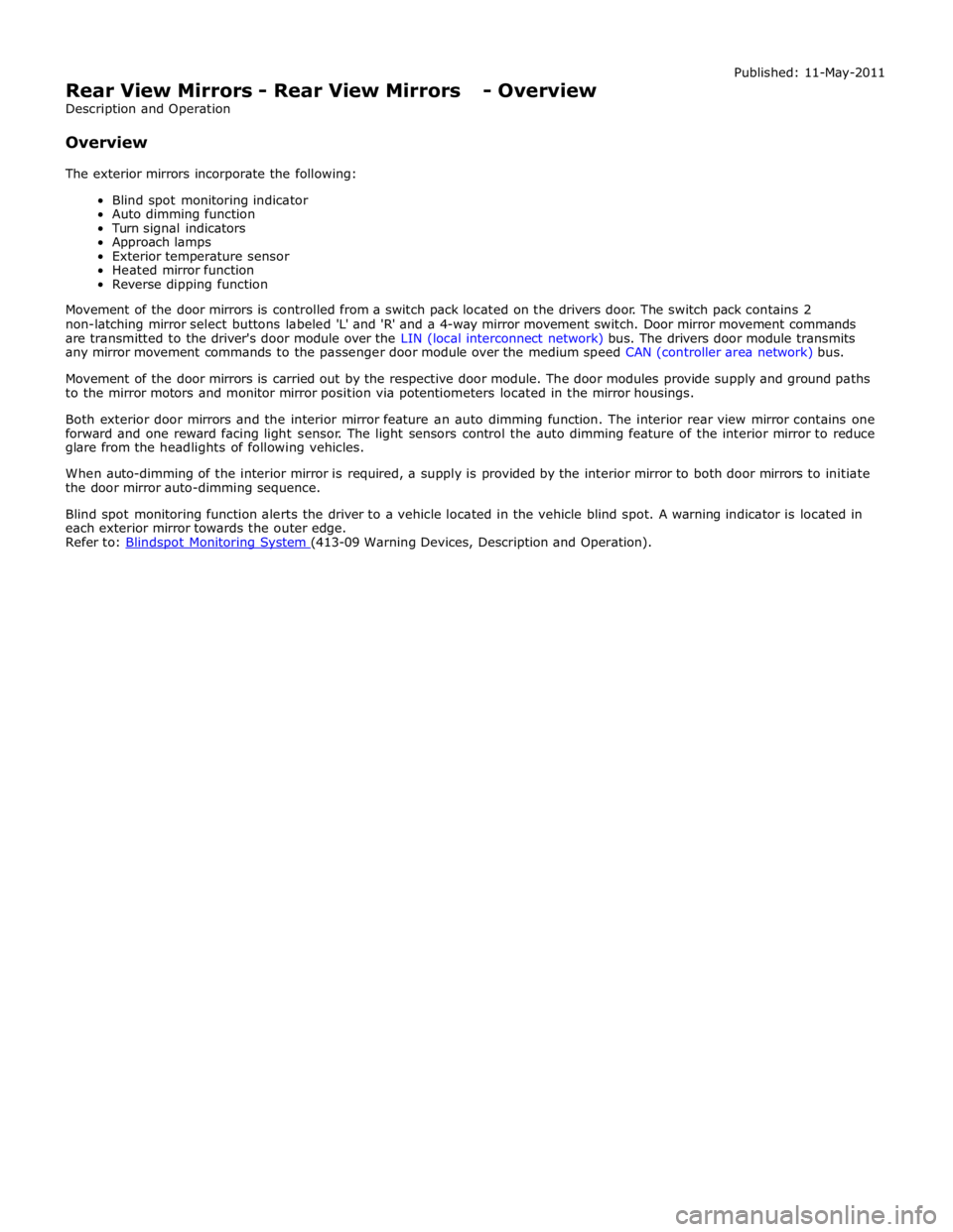
Rear View Mirrors - Rear View Mirrors - Overview
Description and Operation
Overview
The exterior mirrors incorporate the following:
Blind spot monitoring indicator
Auto dimming function
Turn signal indicators
Approach lamps
Exterior temperature sensor
Heated mirror function
Reverse dipping function Published: 11-May-2011
Movement of the door mirrors is controlled from a switch pack located on the drivers door. The switch pack contains 2
non-latching mirror select buttons labeled 'L' and 'R' and a 4-way mirror movement switch. Door mirror movement commands
are transmitted to the driver's door module over the LIN (local interconnect network) bus. The drivers door module transmits
any mirror movement commands to the passenger door module over the medium speed CAN (controller area network) bus.
Movement of the door mirrors is carried out by the respective door module. The door modules provide supply and ground paths
to the mirror motors and monitor mirror position via potentiometers located in the mirror housings.
Both exterior door mirrors and the interior mirror feature an auto dimming function. The interior rear view mirror contains one
forward and one reward facing light sensor. The light sensors control the auto dimming feature of the interior mirror to reduce
glare from the headlights of following vehicles.
When auto-dimming of the interior mirror is required, a supply is provided by the interior mirror to both door mirrors to initiate
the door mirror auto-dimming sequence.
Blind spot monitoring function alerts the driver to a vehicle located in the vehicle blind spot. A warning indicator is located in
each exterior mirror towards the outer edge.
Refer to: Blindspot Monitoring System (413-09 Warning Devices, Description and Operation).
Page 2294 of 3039
8 LH door module 9 Exterior mirror control switches
System Operation
The rear view mirrors comprise an interior mirror mounted to the windshield, and an exterior mirror mounted on each front door
cheater. The types of mirrors and associated operating functions installed depend on the specification and trim level of the
vehicle.
Interior Mirrors
The interior rear view mirror is provided as a manual dimming or an electrically operated automatic dimming type.
The manual dimming mirror comprises a prismatic glass housed within a surrounding case that is attached with a ball joint
connector to the mirror stem. Manual dimming of the mirror is achieved using the lever mounted on the underside of the mirror
body. Operating the lever will tilt the mirror head from the 'day' position to the 'night' position.
The automatic dimming mirror comprises an electro-chromatic glass housed within a surrounding case that is attached with a
ball joint connector to the mirror stem. The mirror stem incorporates an 8-pin electrical connector that is connected to the roof
panel wiring harness. The wiring harness provides hardwired and a LIN connection to the CJB.
Light sensors are mounted on the front and rear of the mirror surround case. The sensors control the automatic dimming
feature to reduce glare from the headlights of following vehicles.
The automatic dimming function is permanently active when the ignition is in power mode 4 (Accessory) and power mode 6
(Ignition). The forward facing light sensor monitors the ambient light level at the front of the vehicle; the rearward facing light
sensor monitors the light level coming from the rear of the vehicle. When light from the rear of the vehicle exceeds the
ambient light level from the front of the vehicle, the automatic dimming circuit darkens the interior mirror surface.
Automatic dimming is inhibited when reverse gear is selected to provide the driver with maximum vision. On vehicles with
automatic transmission, the reverse gear signal is provided by the TCM (transmission control module) via the high speed CAN bus to the CJB. The CJB then provides a power feed to the mirror. On vehicles with manual transmission, the reverse gear signal is provided by a transmission switch that is hardwired to the CJB.
Exterior Mirrors
Electrically operated and heated exterior mirrors are installed as standard. Depending on the specification and trim level of the
vehicle, the following options are available:
Power fold (switch pack operated feature) and auto fold (remote handset operated feature)
Memory recall
Reverse gear mirror dip
Mirror heating
Exterior mirror lamps.
The power fold/auto fold feature is available only when power fold mirrors are installed to the vehicle.
The mirrors can be configured to automatically fold when the vehicle is locked and unfold when unlocked. This feature can be
enabled or disabled via the Vehicle settings area of the touch screen:
Select 'Settings' from the touch screen Home menu.
Select ' Security/Vehicle'
Select 'Windows/Mirrors'
Select Power Fold 'On' or 'Off' as appropriate.
The pasenger side mirror can be configured to automatically dip when reverse gear is selected. This feature can be enabled or
disabled via the Vehicle settings area of the touch screen:
Select 'Settings' from the touch screen Home menu.
Select ' Security/Vehicle'
Select 'Windows/Mirrors'
Select Reverse dip 'On' or 'Off' as appropriate.
The LH door mirror incorporates an ambient air temperature sensor that is hardwired to the ECM (engine control module). The ECM is connected to the CJB and other control modules via the high speed CAN bus. The sensor provides information to the ECM that is then transmitted on the medium speed CAN bus for use by other control modules. On vehicles installed with a high-line instrument cluster, the CJB transmits the temperature signal to the instrument cluster that provides a display of the ambient temperature to the driver.
The exterior mirror lamps are controlled by the interior lighting function.
The door mirrors are controlled using a switch pack located on the driver's door. The switch pack contains 2 non-latching mirror
select switches labeled 'L' and 'R' and a 4-way directional joystick. The switch pack is connected to the driver door control
module via the LIN bus. The driver and front passenger door control modules are connected via the medium speed CAN bus. A hardwired connection between each door control module and the corresponding door mirror, provides the supply and ground
paths for the mirror motors.
Each exterior door mirror incorporates 2 motors to control horizontal (left/right) and vertical (up/down) adjustments. www.JagDocs.com
Page 2295 of 3039
On vehicles installed with a driver's power operated memory seat and memory exterior mirrors, a potentiometer is incorporated
within each mirror motor and is used to provide information regarding the actual motor positions. The current position and
memory positions of each door mirror motor are maintained and stored within the corresponding door control module.
The memory exterior mirror positions are also monitored and stored within door control module memory when the reverse gear
mirror dip function is used.
When reverse gear is selected, the door control module stores the current mirror positions and will then dip the passenger
mirror glass to a default dip position. While reverse gear is selected it is possible to store a preferred dipped mirror position by
adjusting the driver/passenger mirror glass to the desired position via the mirror switch pack. When the desired position is
achieved using the switch, the new dip positions will be automatically stored by the door control module when reverse gear is
de-selected. Therefore when reverse gear is re-selected, the dip position recalled by the door control module will be the new
reverse gear mirror dip stored position. When reverse gear is deselected the mirror glass will automatically move to the previous
stored position prior to reverse gear selection.
If the driver selects a memory recall function using the memory seat switch pack, the driver's memory seat and exterior
memory mirrors are moved to a stored memory position.
Exterior mirrors with the power fold/auto fold feature incorporate a motor located in the hinge of each exterior mirror arm.
Operation of the power fold feature is achieved using the exterior mirror switch pack. Operation of the auto fold feature is
achieved using the remote handset.
The power fold function is active when the ignition is in power mode 6 (Ignition).
Both exterior mirrors will power fold when the mirror switch pack 'L' and 'R' switches are pressed together. Pressing the
switches again will unfold the mirrors.
When the instrument cluster is configured for the auto fold feature, the mirrors will fold in when the remote handset lock
button is pressed. The mirrors will unfold when the vehicle is unlocked using the remote handset unlock button.
NOTE: If the mirrors are folded in using the mirror switch pack (power fold) and the vehicle is then locked, subsequent
unlocking of the vehicle will not unfold the mirrors.
When the remote handset unlock button is operated, the CJB recognizes the remote handset for that vehicle and acknowledges the request. The door control modules are connected directly to the AJB (auxiliary junction box) for power supply to the
exterior mirror folding motors.
When the vehicle is locked the door control modules reverse the polarity of the mirror fold motor, power and ground
connections to operate the mirrors in the opposite direction.
Exterior mirror heating is provided with heater elements bonded to the back of the mirror glass. Power supply for the mirror
heating elements is provided by the corresponding driver or passenger door control module via the RJB. The door control modules receive a power supply from the RJB, and are both connected on the medium speed CAN bus to the ATC (automatic temperature control) module. A ground terminal from each door control module completes the circuit. The ATC module automatically controls the mirror heating function whenever the ignition is in power mode 4 (Accessory) and power mode 6
(Ignition).
Operation of the exterior mirror heaters is fully automatic and not controllable by the driver. Exterior mirror heater operation is
determined by ambient air temperature and windshield wiper status. When ambient air temperature reaches a pre-determined
level, the ATC module broadcasts an exterior mirror heating request to the door modules over the medium speed CAN bus. On receipt of this message, the door modules provide feed and ground connections to both exterior mirror heater elements.
The mirror heating is controlled in two phases, the initial heating phase and a second PWM (pulse width modulation) controlled
phase. In the first phase the heater elements in the mirrors are permanently powered for a pre-determined length of time. This
length of time varies with the ambient temperature. During the second PWM phase, the heater elements are turned on and off every 30 seconds. The amount of time the exterior mirror heaters are operational increases if the windshield wipers are
switched on. This ensures the mirrors remain mist free in damp and wet conditions, where there is an increased risk of misting.
Page 2315 of 3039
7 Front seat climate control module 8 Passenger seat squab climate module 9 Drivers seat cushion climate module 10 Passenger seat cushion climate module 11 Drivers seat squab climate module 12 Passenger seat cushion heater element 13 Passenger seat squab heater element 14 Drivers seat cushion heater element 15 Drivers seat squab heater element 16 CJB
HEATED SEATS - OPERATION
Heated Front Seats System Operation
The TSD receives a fused power supply from the RJB. One of the 3 seat heat temperature selections made by the driver or passenger using the TSD soft keys are passed from the TSD on the MOST ring to the Information and Entertainment module.
The information and entertainment module processes the information and transmits the request on the medium speed CAN bus to the ATC module.
The cushion heaters have a thermal sensor which supplies a feed back signal back to the CJB. The squab heater elements do not have a thermal sensor and are maintained at the same temperature as the seat cushion elements.
The ATC module reacts to the driver request information received from the information and entertainment module and requests the CJB to activate the seat heaters. The CJB measures the returned temperature signals from the thermal sensors and relays the temperature signals back to the ATC module. The ATC module then uses the measured seat element temperatures to provide closed-loop control of the heater elements to maintain the temperature at one the 3 heat ranges selected.
NOTE: To prevent excessive battery discharge, the heated front seats will only operate when the engine is running.
Heated and Cooled Front Seats
The TSD receives a fused power supply from the RJB. Selections made by the driver using the TSD soft keys are passed from the TSD on the MOST ring to the Information and Entertainment module. The information and entertainment module processes
the information and transmits the request on the medium speed CAN bus to the front seat climate control module. The front seat climate control module is located beneath the RH (right-hand) front seat, on the floor cross member.
The front seat climate control module receives its power supplies from the CJB. Heating and cooling requests are generated using the soft buttons on the TSD. These requests are transmitted to the information and entertainment module over the
MOST ring. The Information and Entertainment module forwards these requests to the front seat climate control module over
the medium speed CAN bus.
The front seat climate control module supplies power to the two climate modules in each seat. The temperature sensor in each
climate module is monitored by the front seat climate control module which uses the temperature information to control the
Peltier cells accordingly and also the blower fans to distribute the heated or cooled air.
NOTE: To prevent excessive battery discharge, the heated and cooled front seats will only operate when the engine is
running.
Electric Driver's Seat Adjustment - Non-Memory Seats
The CJB supplies 3 power supplies to the driver's seat switchpack. The fused supplies provide power for the seat height and squab recline, the seat slide and seat tilt and the lumbar adjustment respectively. The CJB only provides the power to the driver's seat switch pack when the ignition is on (power mode 6).
For the seat movement motors, when the applicable switch is operated, the power is supplied to the applicable side of the
motor and the ground path is completed to operate the motor in the required direction. To move the motor in the opposite
direction the polarity is reversed.
For the lumbar adjustment, when the switch is operated in the inflate position, power is supplied to the pump motor to inflate
the lumbar support. When the switch is operated in the opposite direction, the power energizes a solenoid which in turn opens
a valve to deflate the lumbar support.
Electric Passenger Seat Adjustment ( 8, 10 and 12 way)
The CJB supplies 3 power supplies to the passenger seat switchpack. The fused supplies provide power for the seat height and squab recline, the seat slide and seat tilt and the head restraint and lumbar adjustment respectively. The CJB only provides the power to the passenger seat switch pack when the ignition is on (power mode 6).
For the seat movement and head restraint motors, when the applicable switch is operated, the power is supplied to the
applicable side of the motor and the ground path is completed to operate the motor in the required direction. To move the
Page 2317 of 3039
memory positions to be stored and 'set' button with integral LED (light emitting diode). The seat, door mirror and steering
column motors have position sensors which provide feedback to driver's seat module.
Once the driver's seat, steering column and exterior mirrors have been adjusted, the vehicle is able to memorize these
settings for future use by using the following procedure:
Push the memory 'SET' button, the LED in the switch will illuminate Press the memory button 1 or 2 to memorize the current settings. The LED will extinguish, and a chime will sound to confirm that the settings have been memorized. If the ignition is on, power mode 6, the message center will display a
confirmation message.
The positions can be recalled by pressing the applicable button 1 or 2.
Stall Detection
Seat, steering column and mirror motors are deemed to have stalled if there is no change in the inputs that are received from
the corresponding feedback sensors for 200 ms (seat).
If a stall condition is detected then the drive to that motor is cancelled for the remainder of that memory operation (memory
recall) or until the switch is re-selected (manual movement).
If the motor movement has stopped due to loss of sensor feedback, either stall or sensor failure, then that motor may be
activated again, to move past the stall position, by re-selecting the appropriate switch and pressing for longer than 2 seconds.
This allows control of the motor to be maintained if sensor feedback is lost.
Upon re-selection of movement, if sensor pulses are detected then the motor will continue to be driven until the switch is
released or another stall condition is detected. If sensor feedback is not detected then the motor is only driven for 0.5 second
and then stops until the switch is released and then pressed again, when a further 0.5 second of activation is permitted, and
so on, this is known as inch mode.
For all seat motor manual movements, whenever a motor is driven and a stall occurs, the memory control module records the
position at which the stall occurred. If movement occurs beyond a stall position, then that position is erased from the control
modules memory. This will always allow movement past a previously recorded stall position once movement has been
registered beyond that position. This is the case for both manual and memory movement.
Initialization
When a replacement driver's seat module is fitted, it should be calibrated a Jaguar approved diagnostic system so that the
module can learn the seats absolute position.
Battery Monitor
If the battery voltage drops below 10.5 Volts, then the driver's seat module ignores all requests for a memory recall until the
battery voltage has reached 11.5 Volts. This will conserve as much power in the vehicle battery as possible to enable engine
cranking.
REAR SEATS - DESCRIPTION
The rear seat features a single piece cushion and a 60/40 split squab. Two latches are secured to the rear bulkhead by a pair
of M8 bolts to retain the seat squabs in the upright position. The latches can be released to fold down the individual cushions
by pulling a cable release located below the rear window parcel shelf in the luggage compartment.
ISOFIX fastening points are attached to the vehicle floor to provide secure fastening for compatible child seats.
A centrally mounted center arm rest can be folded down from the 60% squab. The arm rest contains two drinks holders.
Page 2328 of 3039
Seating - Seats
Diagnosis and Testing
Principle of Operation Published: 18-Apr-2013
For a detailed description of the seats and seat operation, refer to the relevant Description and Operation section in the
workshop manual. REFER to: (501-10 Seating)
Seats (Description and Operation), Seats (Description and Operation), Seats (Description and Operation).
Inspection and Verification
CAUTION: Diagnosis by substitution from a donor vehicle is NOT acceptable. Substitution of control modules does not
guarantee confirmation of a fault, and may also cause additional faults in the vehicle being tested and/or the donor vehicle.
NOTE: Prior to carrying out any diagnosis, ensure the vehicle battery is in a good serviceable condition, refer to the
battery care manual.
1. Verify the customer concern.
2. Visually inspect for obvious signs of damage and system integrity.
Visual Inspection
Mechanical Electrical
Security, condition and correct installation of seat components and fixings
Fuses
Harnesses for damage/corrosion
Electrical connectors
Damaged/corroded pins
3. If an obvious cause for an observed or reported concern is found, correct the cause (if possible) before proceeding to
the next step.
4. If the cause is not visually evident, verify the concern and refer to the Symptom Chart, alternatively, check for
Diagnostic Trouble Codes (DTCs) and refer to the DTC Index.
5. Check DDW for open campaigns. Refer to the corresponding bulletins and SSM's which may be valid for the specific
customer complaint and carry out the recommendations as needed.
Symptom Chart
Symptom Possible Cause Action No seat movement from switch pack
(including no memory recall)
Seat module has
gone into sleep
mode
Seat switch pack
LIN, power or
ground circuit -
open circuit
Seat switch pack
LIN circuit - short
to power, ground Set ignition ON. Re-check seat function from switch pack.
Check for DTC B1A9887 and refer to DTC Index. Check for
DTC B1A9888 and refer to DTC Index No seat movement or lumbar movement
from switch pack (including no memory
recall)
NOTE: Seat module
does not control the seat
lumbar function
Seat switch pack
power or ground
supply circuits -
open circuit Refer to the electrical circuit diagrams and check seat
switch pack power and ground supply circuits for open
circuit Seat movement and lumbar movement
from switch pack is ok, however, no recall
from memory switch pack
Seat switch pack to
memory switch
pack circuits -
short, open circuit
NOTE: Memory switch pack is separate switch
hardwired to seat adjust switch
Refer to the electrical circuit diagrams and check seat
switch pack to memory switch pack circuits for short,