303 00 JAGUAR XFR 2010 1.G Workshop Manual
[x] Cancel search | Manufacturer: JAGUAR, Model Year: 2010, Model line: XFR, Model: JAGUAR XFR 2010 1.GPages: 3039, PDF Size: 58.49 MB
Page 1339 of 3039

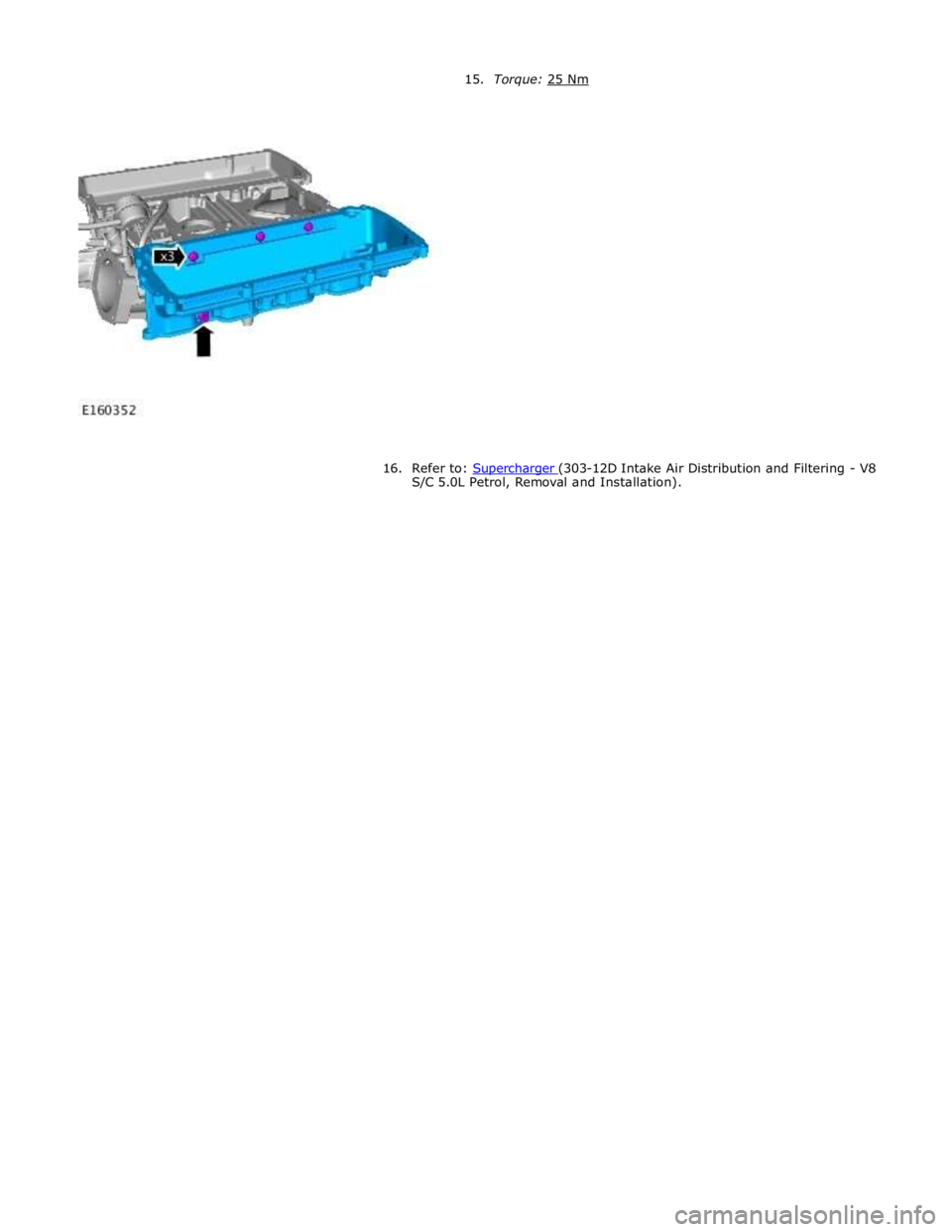
16. Refer to: Supercharger (303-12D Intake Air Distribution and Filtering - V8 S/C 5.0L Petrol, Removal and Installation).
Page 1361 of 3039

DIAGNOSTICS
The ECM stores each fault as a DTC (diagnostic trouble code). The DTC and associated environmental and freeze frame data can be read using Jaguar approved diagnostic equipment, which can also read real time data from each sensor, the adaption
values currently being employed and the current fueling, ignition and idle speed settings.
ENGINE CONTROL MODULE Component Description
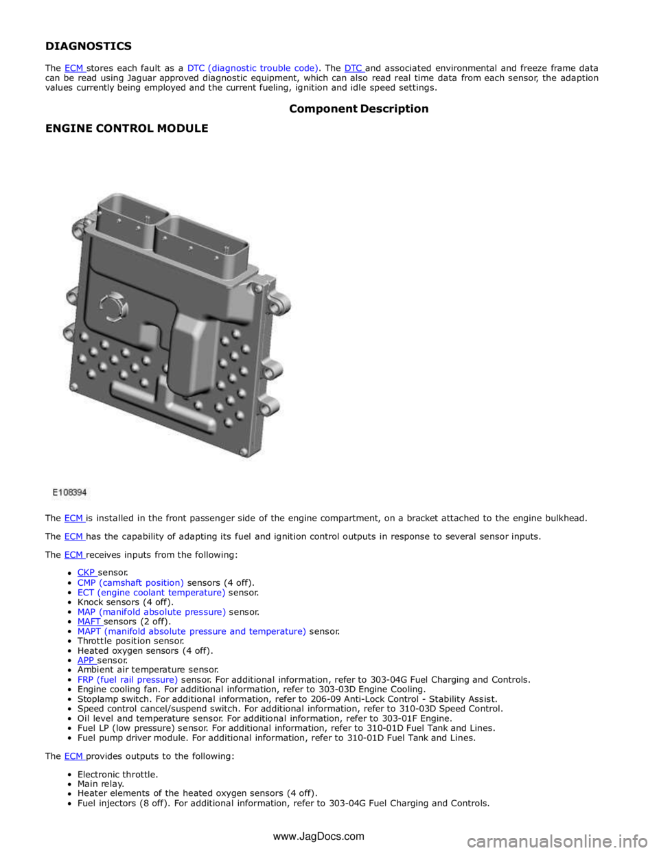
The ECM is installed in the front passenger side of the engine compartment, on a bracket attached to the engine bulkhead. The ECM has the capability of adapting its fuel and ignition control outputs in response to several sensor inputs. The ECM receives inputs from the following:
CKP sensor. CMP (camshaft position) sensors (4 off).
ECT (engine coolant temperature) sensor.
Knock sensors (4 off).
MAP (manifold absolute pressure) sensor.
MAFT sensors (2 off). MAPT (manifold absolute pressure and temperature) sensor.
Throttle position sensor.
Heated oxygen sensors (4 off).
APP sensor. Ambient air temperature sensor.
FRP (fuel rail pressure) sensor. For additional information, refer to 303-04G Fuel Charging and Controls.
Engine cooling fan. For additional information, refer to 303-03D Engine Cooling.
Stoplamp switch. For additional information, refer to 206-09 Anti-Lock Control - Stability Assist.
Speed control cancel/suspend switch. For additional information, refer to 310-03D Speed Control.
Oil level and temperature sensor. For additional information, refer to 303-01F Engine.
Fuel LP (low pressure) sensor. For additional information, refer to 310-01D Fuel Tank and Lines.
Fuel pump driver module. For additional information, refer to 310-01D Fuel Tank and Lines.
The ECM provides outputs to the following: Electronic throttle.
Main relay.
Heater elements of the heated oxygen sensors (4 off).
Fuel injectors (8 off). For additional information, refer to 303-04G Fuel Charging and Controls. www.JagDocs.com
Page 1367 of 3039

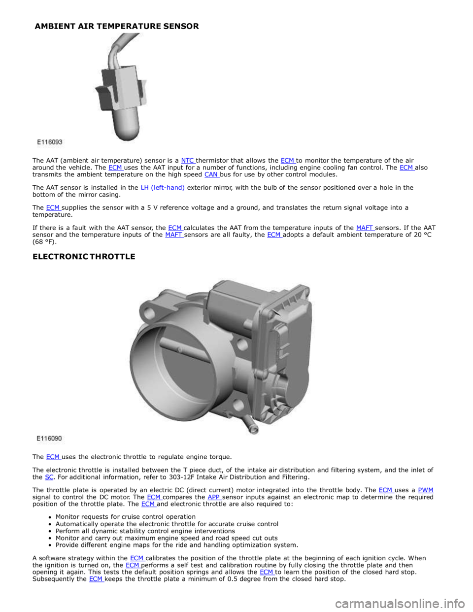
around the vehicle. The ECM uses the AAT input for a number of functions, including engine cooling fan control. The ECM also transmits the ambient temperature on the high speed CAN bus for use by other control modules.
The AAT sensor is installed in the LH (left-hand) exterior mirror, with the bulb of the sensor positioned over a hole in the
bottom of the mirror casing.
The ECM supplies the sensor with a 5 V reference voltage and a ground, and translates the return signal voltage into a temperature.
If there is a fault with the AAT sensor, the ECM calculates the AAT from the temperature inputs of the MAFT sensors. If the AAT sensor and the temperature inputs of the MAFT sensors are all faulty, the ECM adopts a default ambient temperature of 20 °C (68 °F).
ELECTRONIC THROTTLE
The ECM uses the electronic throttle to regulate engine torque.
The electronic throttle is installed between the T piece duct, of the intake air distribution and filtering system, and the inlet of
the SC. For additional information, refer to 303-12F Intake Air Distribution and Filtering.
The throttle plate is operated by an electric DC (direct current) motor integrated into the throttle body. The ECM uses a PWM signal to control the DC motor. The ECM compares the APP sensor inputs against an electronic map to determine the required position of the throttle plate. The ECM and electronic throttle are also required to: Monitor requests for cruise control operation
Automatically operate the electronic throttle for accurate cruise control
Perform all dynamic stability control engine interventions
Monitor and carry out maximum engine speed and road speed cut outs
Provide different engine maps for the ride and handling optimization system.
A software strategy within the ECM calibrates the position of the throttle plate at the beginning of each ignition cycle. When the ignition is turned on, the ECM performs a self test and calibration routine by fully closing the throttle plate and then opening it again. This tests the default position springs and allows the ECM to learn the position of the closed hard stop. Subsequently the ECM keeps the throttle plate a minimum of 0.5 degree from the closed hard stop. AMBIENT AIR TEMPERATURE SENSOR
Page 1369 of 3039

Published: 16-Sep-2013
Electronic Engine Controls - V8 S/C 5.0L Petrol - Electronic Engine Controls
Diagnosis and Testing
Principle of Operation
For a detailed description of electronic engine controls, refer to the relevant Description and Operation section of the workshop
manual. REFER to: (303-14D Electronic Engine Controls - V8 S/C 5.0L Petrol)
Electronic Engine Controls (Description and Operation), Electronic Engine Controls (Description and Operation), Electronic Engine Controls (Description and Operation).
Inspection and Verification
1. Verify the customer concern.
2. Visually inspect for obvious signs of damage and system integrity.
Visual Inspection
Mechanical Electrical
Engine oil level and condition
Cooling system coolant level
Fuel level
Fuel contamination/grade/quality
Throttle body
Front End Accessory Drive (FEAD) belt
Air cleaner condition
Fuses
Wiring harness
Electrical connector(s)
Sensor(s)
Engine Control Module
Transmission Control Module
3. If an obvious cause for an observed or reported concern is found, correct the cause (if possible) before proceeding to
the next step.
4. If the cause is not visually evident, verify the customer concern and refer to the Symptom Chart below, alternatively,
check for Diagnostic Trouble Codes (DTCs) and refer to the DTC Index.
Symptom Chart
Symptom Possible Cause Action Engine non-start Engine does not crank
Security system /Immobilizer
engaged
Engine in shut-down mode
ECM relay
Battery
Starting system
Engine seized
Check that the security system is disarmed
Read DTCs and refer to DTC Index in this
section for ECM relay tests
Ensure the battery is in fully charged and
serviceable condition
For starting system tests refer to the
relevant section of the workshop manual
For engine system tests refer to the relevant
section of the workshop manual Engine cranks, but does not fire
Engine breather system
disconnected/restricted
Ignition system
Fuel system
Electronic engine controls
Ensure the engine breather system is free
from restriction and is correctly installed
For ignition system tests refer to the
relevant section of the workshop manual
For fuel system tests refer to the relevant
section of the workshop manual
Read DTCs and refer to DTC Index in this
section for electronic engine control tests Engine cranks and fires, but will not
start
Evaporative emissions purge
valve
Fuel pump
Spark plugs
Ignition coil failure(s)
For purge valve tests refer to the relevant
section of the workshop manual
For fuel system tests refer to the relevant
section of the workshop manual
For ignition system tests refer to the
relevant section of the workshop manual Difficult to start Difficult cold start
Check engine coolant
level/anti-freeze content
Battery
Electronic engine controls
Exhaust gas recirculation
Check the engine coolant level and
condition. Refer to the relevant sections of
the workshop manual
Ensure the battery is in a fully charged and
serviceable condition. Refer to the battery
Page 1376 of 3039

Published: 11-May-2011
Electronic Engine Controls - V8 S/C 5.0L Petrol - Camshaft Position (CMP)
Sensor LH
Removal and Installation
Removal
NOTE: Removal steps in this procedure may contain installation details.
1. Disconnect the battery ground cable.
Refer to: Specifications (414-00 Charging System - General Information,
Specifications).
2. WARNING: Make sure to support the vehicle with axle stands.
Raise and support the vehicle.
3. Refer to: Thermostat Housing - 5.0L SC V8 - AJ133 (303-03 Engine
Cooling - 5.0L NA V8 - AJ133/5.0L SC V8 - AJ133, Removal and
Installation).
Installation
4. NOTE: Some variation in the illustrations may occur,
but the essential information is always correct.
Torque: 10 Nm
1. CAUTIONS:
Make sure that the mating faces are clean and free of foreign
material.
Make sure that the sensor tip is clean and free of foreign material.
NOTE: Lubricate the O-ring seal with clean engine oil.
To install, reverse the removal procedure. www.JagDocs.com
Page 1377 of 3039

Published: 11-May-2011
Electronic Engine Controls - V8 S/C 5.0L Petrol - Camshaft Position (CMP)
Sensor RH
Removal and Installation
Removal
NOTE: Removal steps in this procedure may contain installation details.
1. Disconnect the battery ground cable.
Refer to: Specifications (414-00 Charging System - General Information,
Specifications).
2. WARNING: Make sure to support the vehicle with axle stands.
Raise and support the vehicle.
3. Refer to: Thermostat Housing - 5.0L SC V8 - AJ133 (303-03 Engine
Cooling - 5.0L NA V8 - AJ133/5.0L SC V8 - AJ133, Removal and
Installation).
Installation
4. NOTE: Some variation in the illustrations may occur,
but the essential information is always correct.
Torque: 10 Nm
1. CAUTIONS:
Make sure that the mating faces are clean and free of foreign
material.
Make sure that the sensor tip is clean and free of foreign material.
NOTE: Lubricate the O-ring seal with clean engine oil.
To install, reverse the removal procedure.
Page 1379 of 3039

Installation 5. CAUTION: Make sure that the mating faces are clean
and free of foreign material.
Torque: 48 Nm
1. CAUTIONS:
If accidentally dropped or knocked install a new sensor.
Make sure the catalyst monitor sensor wiring harness is not twisted
more than 180 degrees and is not in contact with either the exhaust or
driveshaft.
Make sure the anti-seize compound does not contact the catalyst
monitor sensor tip.
NOTE: If the original sensor is to be installed, apply lubricant
meeting specification ESE-M12A4-A to the thread of the sensor.
To install, reverse the removal procedure.
2. NOTE: For NAS vehicles only.
If required, carry out a long drive cycle.
Refer to: Powertrain Control Module (PCM) Long Drive Cycle Self-Test (303-14D Electronic Engine Controls - V8 S/C 5.0L Petrol, General
Procedures).
Page 1381 of 3039

Installation
1. CAUTIONS:
Make sure the anti-seize compound does not contact the catalyst
monitor sensor tip.
If accidentally dropped or knocked install a new sensor.
Make sure the catalyst monitor sensor wiring harness is not twisted
more than 180 degrees and is not in contact with either the exhaust or
driveshaft.
NOTE: If the original sensor is to be installed, apply lubricant
meeting specification ESE-M12A4-A to the thread of the sensor.
To install, reverse the removal procedure.
2. NOTE: For NAS vehicles only.
If required, carry out a long drive cycle.
Refer to: Powertrain Control Module (PCM) Long Drive Cycle Self-Test (303-14D Electronic Engine Controls - V8 S/C 5.0L Petrol, General
Procedures). www.JagDocs.com
Page 1387 of 3039

Published: 19-Aug-2013
Electronic Engine Controls - V8 S/C 5.0L Petrol - Engine Coolant Temperature
(ECT) Sensor
Removal and Installation
Removal
NOTES:
Some variation in the illustrations may occur, but the essential information is always correct.
Removal steps in this procedure may contain installation details.
1. WARNING: Do not work on or under a vehicle supported only by a jack.
Always support the vehicle on safety stands.
Raise and support the vehicle.
2. Refer to: Cooling System Partial Draining, Filling and Bleeding (303-03B Engine Cooling - V6 3.0L Petrol, General Procedures).
3. Refer to: Catalytic Converter RH (309-00C Exhaust System - V8 5.0L Petrol/V8 S/C 5.0L Petrol, Removal and Installation).
4. Torque: 48 Nm
Page 1389 of 3039

Published: 11-May-2011
Electronic Engine Controls - V8 S/C 5.0L Petrol - Engine Oil Level Sensor
Removal and Installation
Removal
NOTE: Removal steps in this procedure may contain installation details.
1. WARNING: Do not work on or under a vehicle supported only by a jack.
Always support the vehicle on safety stands.
Raise and support the vehicle.
2. Refer to: Air Deflector (501-02 Front End Body Panels, Removal and Installation).
3. Refer to: Engine Oil Draining and Filling (303-01D Engine - V8 S/C 5.0L Petrol, General Procedures).
Installation
4. CAUTION: Be prepared to collect escaping fluids.
Torque: 11 Nm
1. CAUTION: A new O-ring seal is to be installed.
To install, reverse the removal procedure.