303 00 JAGUAR XFR 2010 1.G Workshop Manual
[x] Cancel search | Manufacturer: JAGUAR, Model Year: 2010, Model line: XFR, Model: JAGUAR XFR 2010 1.GPages: 3039, PDF Size: 58.49 MB
Page 1406 of 3039

Published: 11-May-2011
Electronic Engine Controls - V8 S/C 5.0L Petrol - Variable Valve Timing (VVT)
Oil Control Solenoid RH
Removal and Installation
Removal
NOTE: Removal steps in this procedure may contain installation details.
1. Disconnect the battery ground cable.
Refer to: Specifications (414-00, Specifications).
2. WARNING: Make sure to support the vehicle with axle stands.
Raise and support the vehicle.
3. Refer to: Thermostat Housing - Vehicles With: Supercharger (303-03,
Removal and Installation).
4. NOTE: Some variation in the illustrations may occur, but
the essential information is always correct.
5. NOTE: Some variation in the illustrations may occur,
but the essential information is always correct.
Torque: 10 Nm www.JagDocs.com
Page 1407 of 3039

Installation 6. CAUTION: Evenly and progressively, remove the VVT
units from each side.
NOTE: Some variation in the illustrations may occur,
but the essential information is always correct.
1. CAUTION: Make sure that the mating faces are clean and free of
foreign material.
NOTE: Lubricate the O-ring seal with clean engine oil.
To install, reverse the removal procedure.
2. NOTE: For NAS vehicles only.
If required, carry out a short drive cycle.
Refer to: Powertrain Control Module (PCM) Short Drive Cycle Self-Test (303-14D Electronic Engine Controls - V8 S/C 5.0L Petrol, General
Procedures).
Page 1460 of 3039

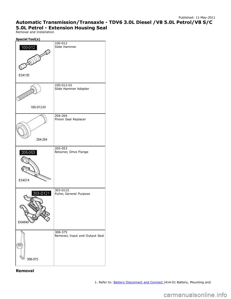
100-012-01
Slide Hammer Adapter
204-264
Pinion Seal Replacer
205-053
Retainer, Drive Flange
303-D121
Puller, General Purpose
308-375
Remover, Input and Output Seal Removal
1. Refer to: Battery Disconnect and Connect (414-01 Battery, Mounting and
Page 1461 of 3039

Cables, General Procedures).
2. WARNING: Make sure to support the vehicle with axle stands.
Raise and support the vehicle.
3. Refer to: Driveshaft - TDV6 3.0L Diesel (205-01 Driveshaft, Removal and Installation).
4. Refer to: Transmission Support Insulator - TDV6 3.0L Diesel (307-01B Automatic Transmission/Transaxle - TDV6 3.0L Diesel /V8 5.0L Petrol/V8
S/C 5.0L Petrol, Removal and Installation).
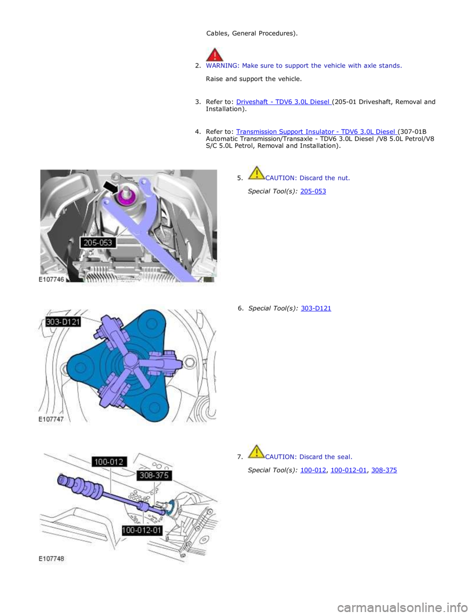
5. CAUTION: Discard the nut.
Special Tool(s): 205-053
6. Special Tool(s): 303-D121 7. CAUTION: Discard the seal.
Special Tool(s): 100-012, 100-012-01, 308-375
Page 1516 of 3039

20. NOTE: For NAS vehicles only.
If required, carry out a long drive cycle.
Refer to: Powertrain Control Module (PCM) Long Drive Cycle Self-Test (303-14D Electronic Engine Controls - V8 S/C 5.0L Petrol, General
Procedures).
Page 1519 of 3039

Published: 11-May-2011
Transmission/Transaxle Cooling - TDV6 3.0L Diesel /V8 5.0L Petrol/V8 S/C 5.0L Petrol - Transmission Cooling - Overview
Description and Operation
OVERVIEW
Transmission cooling is provided by a transmission fluid cooler, which transfers heat from the transmission to the engine
cooling system. The transmission fluid cooler is attached to a mounting bracket on the front subframe, in the front left corner
of the engine compartment.
Two hose and pipe assemblies connect the transmission fluid cooler to the automatic transmission. Two engine coolant hose
connections are incorporated into the top of the transmission fluid cooler for the supply and return of coolant from the engine
cooling system. For additional information, refer to 303-03D Engine Cooling.
Page 1522 of 3039

Published: 11-May-2011
Transmission/Transaxle Cooling - TDV6 3.0L Diesel /V8 5.0L Petrol/V8 S/C 5.0L Petrol - Transmission Fluid Cooler V8 5.0L Petrol/V8 S/C 5.0L Petrol
Removal and Installation
Removal
NOTE: Removal steps in this procedure may contain installation details.
1. WARNING: Make sure to support the vehicle with axle stands.
Raise and support the vehicle.
2. Refer to: Transmission Fluid Drain and Refill (307-01B Automatic Transmission/Transaxle - TDV6 3.0L Diesel /V8 5.0L Petrol/V8 S/C 5.0L
Petrol, General Procedures).
3. Refer to: Cooling System Draining and Vacuum Filling (303-03C Engine Cooling - V8 5.0L Petrol/V8 S/C 5.0L Petrol, General Procedures).
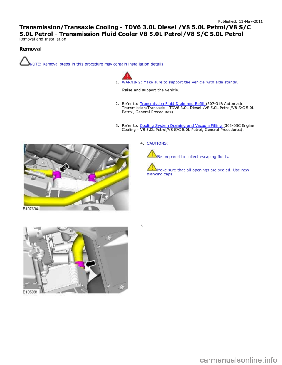
4. CAUTIONS:
Be prepared to collect escaping fluids.
Make sure that all openings are sealed. Use new
blanking caps.
5.
Page 1549 of 3039

Published: 11-May-2011
Exhaust System - V8 5.0L Petrol/V8 S/C 5.0L Petrol - Exhaust System
Diagnosis and Testing
Principle of Operation
For a detailed description of the exhaust system, refer to the relevant Description and Operation section of the workshop
manual. REFER to: (309-00C Exhaust System - V8 5.0L Petrol/V8 S/C 5.0L Petrol)
Exhaust System (Description and Operation), Exhaust System (Description and Operation), Exhaust System (Description and Operation).
Inspection and Verification
CAUTION: Diagnosis by substitution from a donor vehicle is NOT acceptable. Substitution of control modules does not
guarantee confirmation of a fault and may also cause additional faults in the vehicle being checked and/or the donor vehicle.
NOTE: Check and rectify basic faults before beginning diagnostic routines involving pinpoint tests.
1. Verify the customer concern.
2. Visually inspect for obvious signs of damage and system integrity.
3. If an obvious cause for an observed or reported concern is found, correct the cause (if possible) before proceeding to
the next step.
4. If the cause is not visually evident, verify the symptom and refer to the Symptom Chart, alternatively check for
Diagnostic Trouble Codes (DTCs) and refer to the DTC Index.
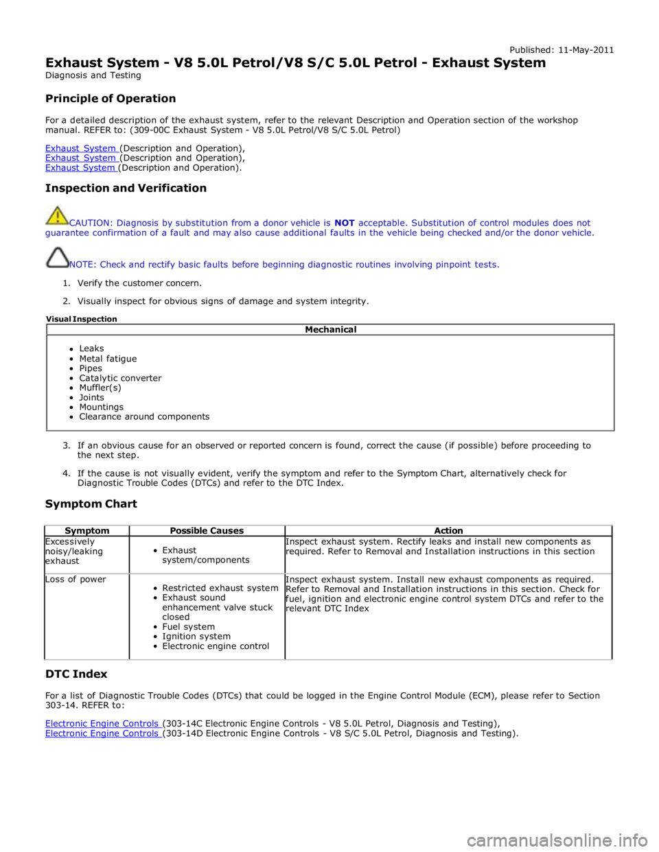
Symptom Chart
Symptom Possible Causes Action Excessively
noisy/leaking
exhaust
Exhaust
system/components Inspect exhaust system. Rectify leaks and install new components as
required. Refer to Removal and Installation instructions in this section Loss of power
Restricted exhaust system
Exhaust sound
enhancement valve stuck
closed
Fuel system
Ignition system
Electronic engine control Inspect exhaust system. Install new exhaust components as required.
Refer to Removal and Installation instructions in this section. Check for
fuel, ignition and electronic engine control system DTCs and refer to the
relevant DTC Index
DTC Index
For a list of Diagnostic Trouble Codes (DTCs) that could be logged in the Engine Control Module (ECM), please refer to Section
303-14. REFER to:
Electronic Engine Controls (303-14C Electronic Engine Controls - V8 5.0L Petrol, Diagnosis and Testing), Electronic Engine Controls (303-14D Electronic Engine Controls - V8 S/C 5.0L Petrol, Diagnosis and Testing). Mechanical
Leaks
Metal fatigue
Pipes
Catalytic converter
Muffler(s)
Joints
Mountings
Clearance around components Visual Inspection
Page 1552 of 3039

2. NOTE: For NAS vehicles only.
If required, carry out a long drive cycle.
Refer to: Powertrain Control Module (PCM) Long Drive Cycle Self-Test (303-14D Electronic Engine Controls - V8 S/C 5.0L Petrol, General
Procedures).
www.JagDocs.com
Page 1555 of 3039

2. NOTE: For NAS vehicles only.
If required, carry out a long drive cycle.
Refer to: Powertrain Control Module (PCM) Long Drive Cycle Self-Test (303-14D Electronic Engine Controls - V8 S/C 5.0L Petrol, General
Procedures).